Liquid Metal Embrittlement (LME) during Resistance Spot Welding (RSW) can cause cracks when welding advanced high strength steels. Recent advances in steel metallurgy, resistance spot welding processing and accompanying simulation tools have substantially improved the way that LME can be handled in industrial practice. This article gives a brief overview of easy measures to implement when LME might potentially occur during production.
Introduction
During resistance spot welding of zinc-coated advanced high strength steels (AHSS) liquid metal embrittlement -related cracking may be observed. Since LME is often associated with a reduction of steel’s mechanical properties, it is desired to control its occurrence during production. An exemplary LME crack, forced with increased weld heat and deliberate electrode misalignment, is shown below.
Figure 1: A typical LME crack created under laboratory conditions by deliberately increasing the welding time and introducing 5° electrode tilt
Over the past several years, LME has been a a focus in welding research. It is now well-understood to the degree that it can be predicted and avoided with easy measures. Below is an overview of four key steps to address the potential of LME during automotive production.
Obtain the latest steel grades from your steel supplier
Over the past decade, steel producers have released AHSS with improved chemical compositions, helping to significantly reduce the occurrence of LME iIt is beneficial to talk with steel suppliers and ask about their latest AHSS grades, as these are likely far less sensitive to LME than previously tested grades. A recent study commissioned by WorldAutoSteel[Link to LME component study] demonstrated that all five chosen material stack-ups from current production data did not show any LME even under exacerbated conditions. Only by choosing an especially difficult material stack-up could LME be forced to appear at all to conduct the study.
Read up on the current state of research for LME
WorldAutoSteel has published two studies on liquid metal embrittlement: One focused on lab conditions and the second on real-life stamped components. These studies provide an overview of all aspects of LME and how to manage and avoid LME issues. [Link to both studies]
Establish in-house testing protocols to gauge the sensitivity of your material stack-ups
To investigate LME in-house, it’s critical to establish a testing protocol that forces the cracks to appear and allows for comparison of different steels, stack-ups and welding parameters. as there There is currently no industry-wide agreed-upon testing standard.
Still, there is a good selection of well-documented procedures to choose from. The easiest procedure is to increase the welding time until cracks start to appear – keep in mind that you need to remove the zinc coating before you can observe any cracks on the surface.
Other methods are based on so-called “Gleeble testing” or on deliberately introducing imperfections like tilted electrodes or large gaps into the welds. As you establish a testing procedure in your lab, you can use it to evaluate LME occurrence in the stack-ups that you want to implement into body-in-whites.
Think about implementing LME mitigation strategies in your most difficult welds
Suitable measures should always be adapted to the specific use case. Generally, the most effective measures for LME prevention or mitigation are:
Avoidance of excessive heat input (e.g. excess welding time, current)
Avoidance of sharp edges on spot welding electrodes; instead use electrodes with larger working plane diameter, while not increasing nugget-size
Employing extended hold times to allow for sufficient heat dissipation and lower surface temperatures
Avoidance of improper welding equipment (e.g. misalignments of the welding gun, highly worn electrodes, insufficient electrode cooling)
These measures can be implemented in the planning stage and in an ongoing production environment to increase the LME-free process windows.
In Conclusion
While Liquid Metal Embrittlement may present a challenge when welding AHSS, it’s no longer an unpredictable threat. Thanks to advancements in steel development, welding techniques, and testing methods, manufacturers have the tools they need to reliably mitigate LME during production.
Staying informed, working closely with steel suppliers, implementing smart testing protocols, and applying targeted welding strategies can help automakers maintain both strength and quality in AHSS joints. With this proactive approach, LME doesn’t have to stand in the way of innovation in automotive manufacturing.
As with resistance spot welding in automotive applications, projection welding also is used to join two overlapping sheets of relatively thin metal. The process involves pressing a projection or number of projections in one of the plates and welding the two plates together at the projection locations.
The method can also be used for welding metal sheet to the ends of bars, rods or pipes, or for welding bolts, nuts, and other attachments to sheets. Such attachments are being used widely in the automotive industry. Wire grids (i.e. the crossing points of the wires) are also particularly suitable for projection welding (it is also called cross wire welding).
A modern car body may contains some 300 welded and punched fasteners, such as bolts, nuts, and studs. The quality of the attachment of these fasteners to the stamped body components is critical for the final product’s safety and reliability. Crucial components such as the front and rear axles are mounted to such fasteners, the seat belts and steering column are anchored to them, and they provide grounding for electrical wires.L-25
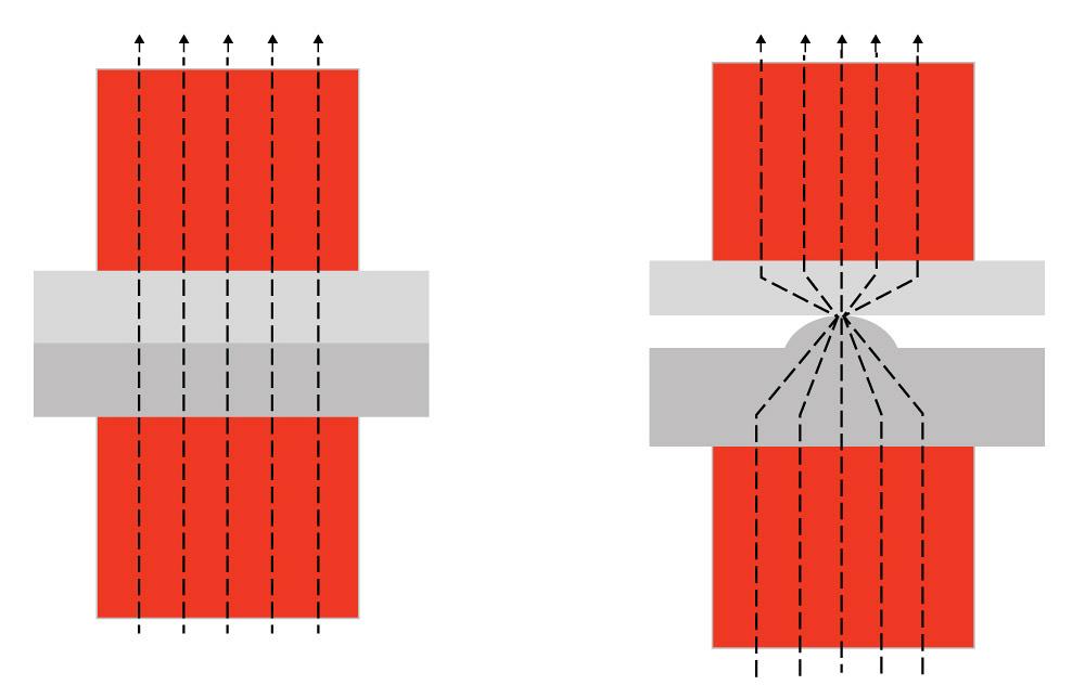
As noted, projection welding is similar to resistance spot welding. However, in the Resistance Spot Welding process, the size of the contact surface of the electrode cap tip determines the current flow, whereas in projection welding, the current flow is constricted to the embossed or machined projection as shown in Figure 1. Both AC and DC power sources are suitable for fastener welding. The heat balance for projection welding is affected by the following factorsA-11:
Projection design and location
Thickness of the sheet to which the fastener is attached
Thermal and electrical conductivities of the metals being welded
Heating rate
Electrode alloy type
As compared to Resistance Spot and Seam Welding, Resistance Projection Welding is capable of welding much thicker parts, as well as parts with a significant thickness mismatch. As a result, it is often considered as a potential replacement for arc welding processes such as GMAW. One of the reasons for this is the drastic reduction in welding time that can be achieved. For example, a typical automotive part that might require several minutes or more of welding with the GMAW process may have the potential to be welded in less than a few seconds with the Resistance Projection Welding process. This is because the entire weld or multiple welds can be made at the same time in a single fixture. Another advantage of the process, relative to spot welding, is that there is less wear and tear on the electrodes.
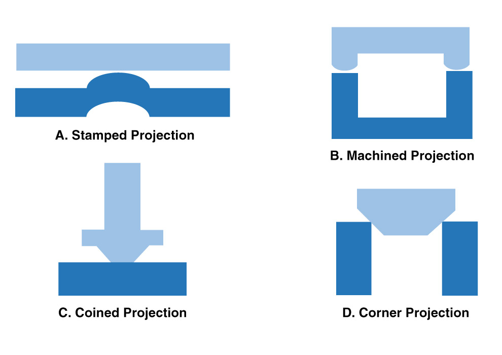
Different types of projections made by different methods are shown in Figure 2. It is important to note that the types of projections that are extensions of the part are known as solid projections (2-B and 2-D) and can only be produced by a machining or forging process, whereas the other projections are more easily produced by stamping with a punch and die. Projections produced with a punch and die usually involve the formation of a molten nugget during welding but not always. The solid projection designs mostly result in solid‐state welds that occur via a forging action as the projection is heated and pressure applied. A common Projection Welding application that uses solid projections involves the attachment of a wide variety of nuts, bolts, and fasteners. Many fasteners used on automobiles are attached this way.
Figure 1: Welding current flow concentration due to projection geometry.
This paper summarizes a paper, entitled “Resistance Welding Projection Methodologies as Applied to Hot-Stamped Boron”, by D. Crist, et al.C-11
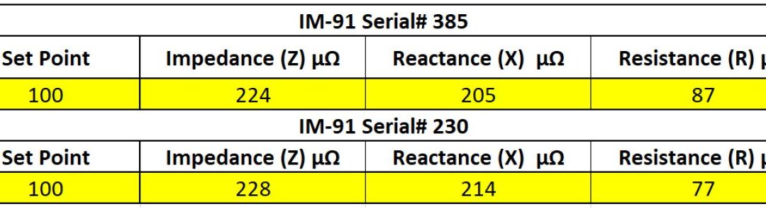
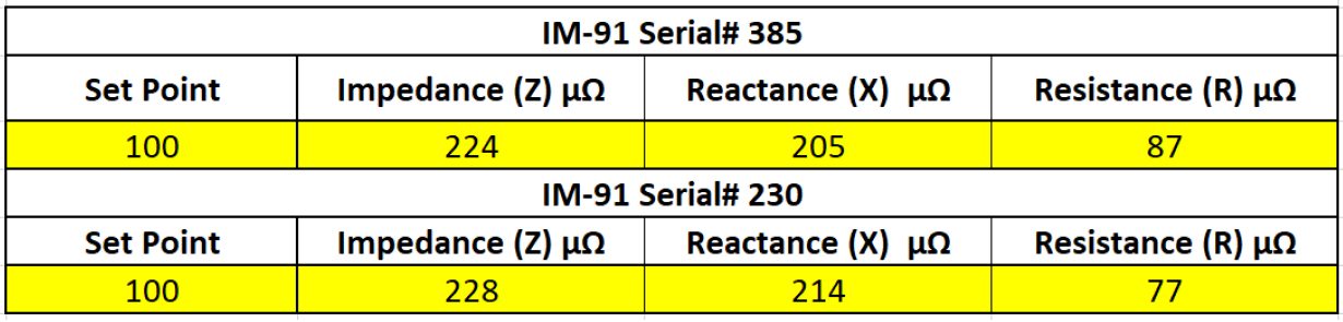
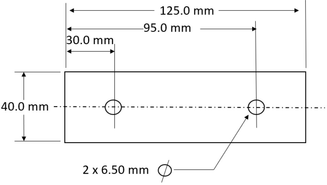
The study focuses on two different Resistance Projection Welding approaches and compares the welding parameters, mechanical properties and destructive results. Table 1 lists the secondary impedance measurements and Table 2 lists the material information for the PHS-CR1500T-MB-AS.
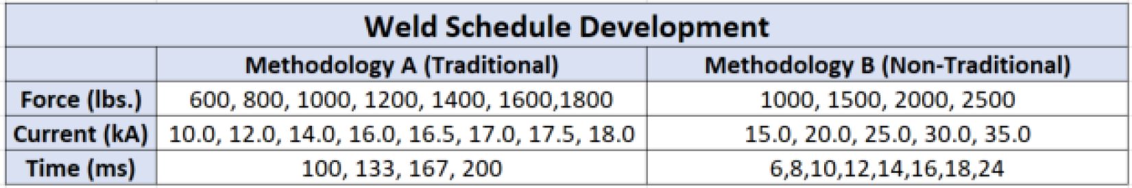
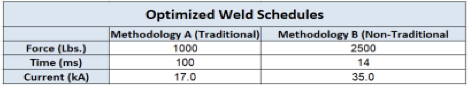
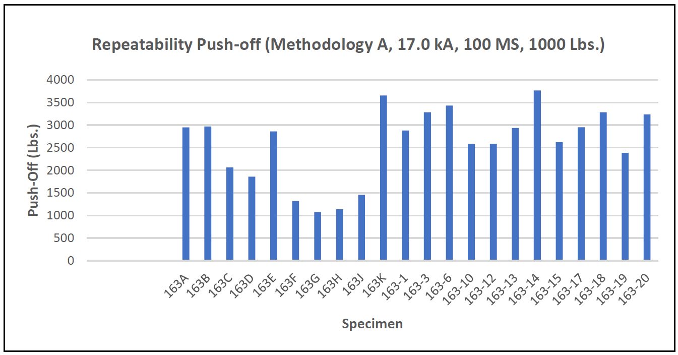
Table 3 lists the weld schedule methodologies tested in this study. Table 4 shows the optimized weld schedules based upon push-off strength and visual weld flash level.
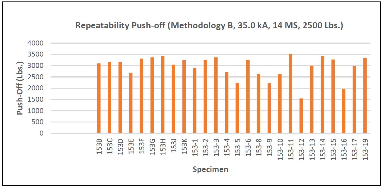
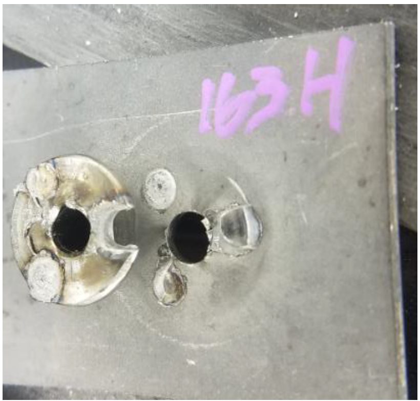
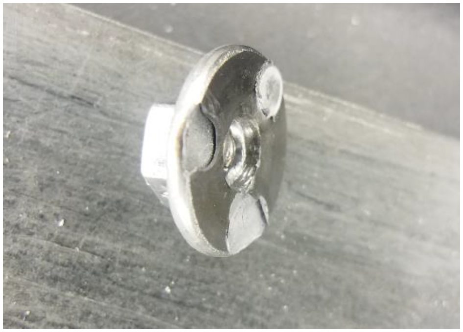
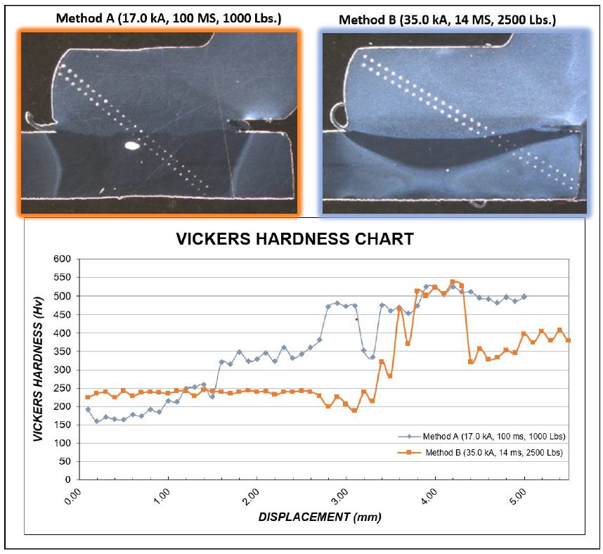
Two different failure methods were observed. Figure 5 shows full thickness buttons were pulled thought the flange for Method A and Figure 6 demonstrates partial thickness failure for Method B.
Figure 5: Method A (17.0 kA, 100 ms, 1000 lb.) Common Failure Mode.C-11
Figure 6: Method B (35.0 kA, 14 ms, 2500 lb.) Common Failure Mode.C-11
Figure 7 shows the microhardness traverse results for both Methods A and B. Method A yields a much larger HAZ. Method B shows a much smaller HAZ, less impact on the base material, and appears to be a solid state bond.
This article summarizes a paper entitled, “Weld Quality Study of Projection Nut Welding with Modular Weld Head”, by F. Jiao, et al.F-7
The study investigates the weld quality of projection nut welding with a patent pending “quick release” modular weld head.
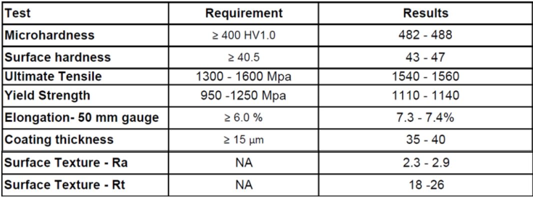
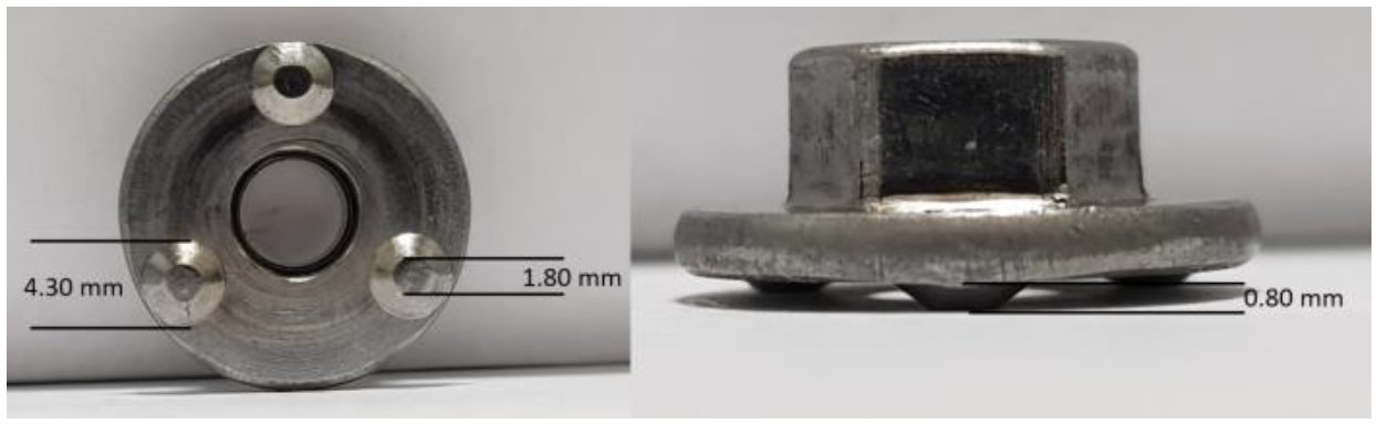
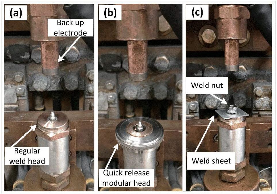
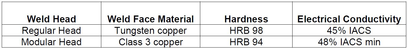
The weld nuts used in the study were 3 projection hex-flanged M6 weld nuts. Operating weld currents ranged from 26-32 kA. The welding time was 5 cycles and the applied electrode force was 450 lb. Figure 1 shows the set up for each test. Figure 2 shows the disassembled parts of the quick release modular weld head. Table 1 lists the material properties of the weld faces.
Figure 1: Projection Nut Welding Set-Up [(a) with regular weld head, (b) with quick-release modular head, and (c) welding parts set up].F-7
Figure 2: Disassembled Parts of Patent-Pending Quick-Release Modular Weld Head.F-7
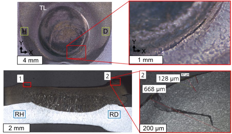
Figure 3 shows the cross section images of the projection welds. Both welds made a weld with 100-micron penetration. The weld made with the regular head had a slightly deeper HAZ as indicated by the dashed line. Figure 4 shows the microhardness profile of both projection welds. Generally, the hardness profile of the welds is quite similar.
Figure 3: Optical Microscope Images of the Projection Welds After Etching [(a) with regular head (b) with modular head].F-7
Figure 4: Microhardness of the Projection-Welded Sample with Different Weld Heads.F-7
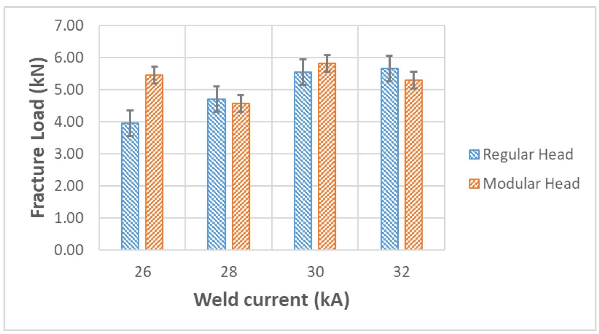
Figure 5 shows the results of tensile testing on both projection welds. The fracture load with the modular head is higher than that with the regular head at 26 kA. At other currents, the fracture load is very similar.
Figure 5: Variation of Fracture Load with Weld Current for Different Weld Head.F-7
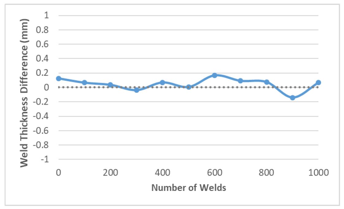
Figure 6 shows the weld thickness difference between the modular head and the regular head. The results indicate the weld performance of both heads is very similar up to 1000 welds.
Figure 6: Variation of Weld Thickness Difference Between Regular Head and Modular Head.F-7

![Figure 1: Projection Nut Welding Set-Up [(a) with regular weld head, (b) with quick-release modular head, and (c) welding parts set up].](http://ahssinsights.org/wp-content/uploads/2020/07/3122_fig1.jpg)

![Figure 3: Optical Microscope Images of the Projection Welds After Etching [(a) with regular head (b) with modular head].](http://ahssinsights.org/wp-content/uploads/2020/07/3122_fig3.jpg)