Blog, main-blog, News
You’ll find this content as part of our page on Roll Forming, but this month, we want to highlight it in our AHSS Insights blog. Thanks to Brian Oxley, Product Manager, Shape Corporation, and Dr. Daniel Schaeffler, President, Engineering Quality Solutions, Inc., and Technical Editor – Metallurgy and Forming, AHSS Application Guidelines, for this case study.
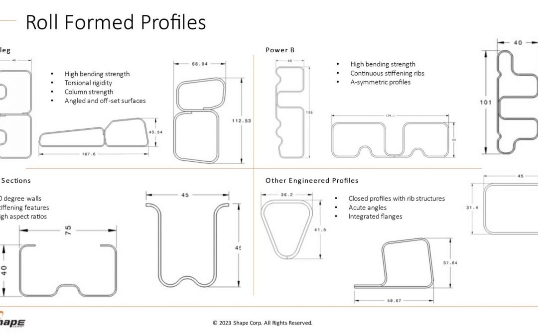
Roll forming is no longer limited to producing simple circular, oval, or rectangular profiles. Advanced cross sections, such as those shown in Figure 1, highlight some profile designs that aid in body structure stiffness and packaging space reductions.
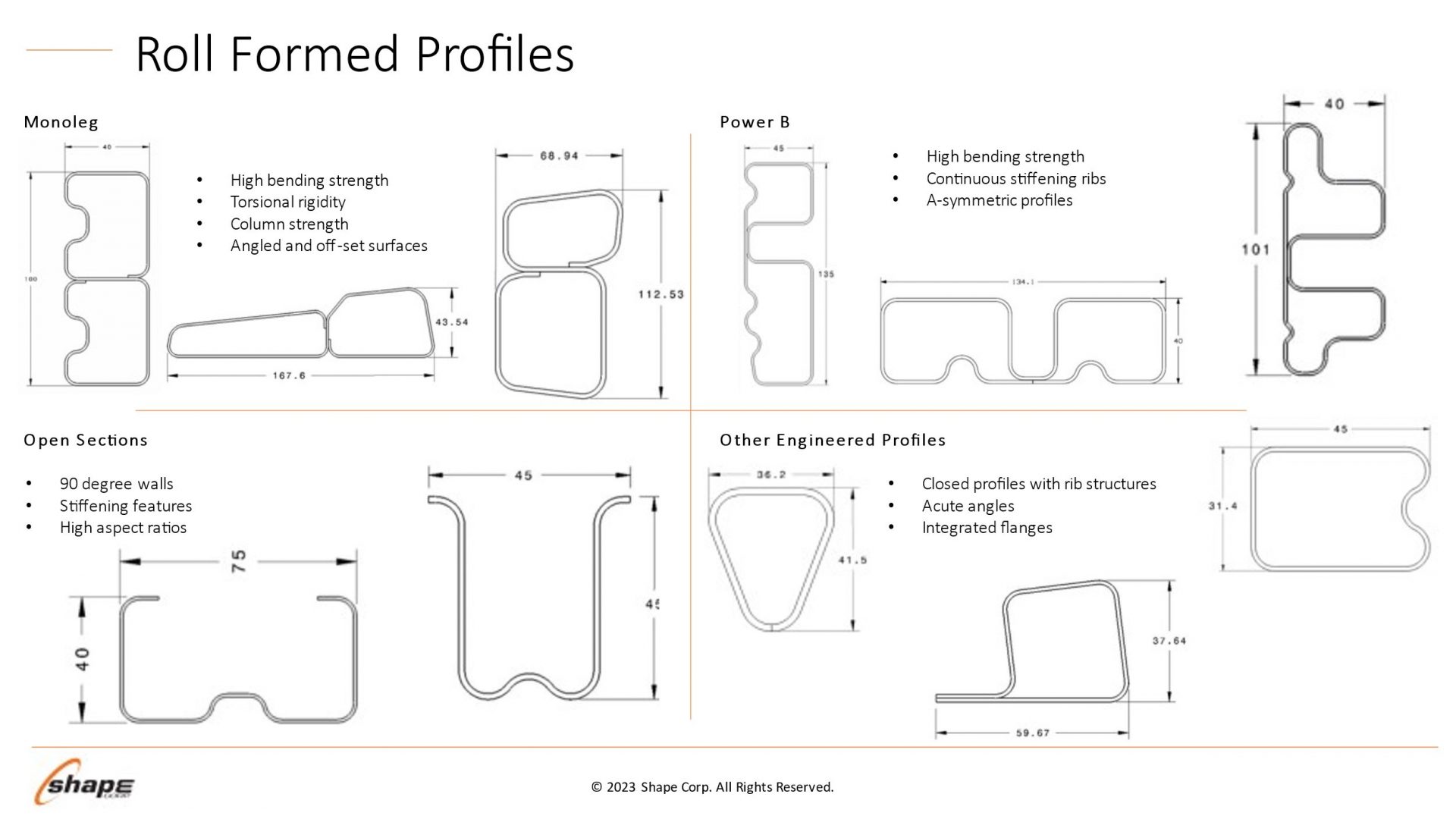
Figure 1 – Roll forming profile design possibilities. Courtesy of Shape Corporation.
Optimizing the use of roll forming requires understanding how the sheet metal behaves through the process. Making a bend in a roll-formed part occurs only when forming forces exceed the metal’s yield strength, causing plastic deformation to occur. Higher-strength sheet metals increase forming force requirements, leading to the need to have larger shaft diameters in the roll forming mill. Each pass must have greater overbend to compensate for the increasing springback associated with the higher strength.
Although a high-strength material requires greater forming loads, grades with higher yield strength can resist stretching of the strip edge and prevent longitudinal deformations such as twisting or bowing.
Force requirements for piercing operations are a function of the sheet tensile strength. High strains in the part design exceeding uniform elongation resulting from loads in excess of the tensile strength produce local necking, representing a structural weak point. However, assuming the design does not produce these high strains, the tensile strength has only an indirect influence on the roll forming characteristics.
Yield strength and flow stress are the most critical steel characteristics for roll forming dimensional control. Receiving metal with limited yield strength variability results in consistent part dimensions and stable locations for pre-pierced features.
Flow stress represents the strength after some amount of deformation and is therefore directly related to the degree of work hardening: starting at the same yield strength, a higher work hardening steel will have a higher flow stress at the same deformation.
Two grades are shown in Figure 2: ZE 550 and CR420Y780T-DP. ZE 550, represented by the red curve, is a recovery annealed grade made by Bilstein having a yield strength range of 550 to 625 MPa and a minimum tensile strength of 600 MPa, while CR420Y780T-DP, represented by the blue curve, is a conventional dual phase steel with a minimum yield strength of 420 MPa and a minimum tensile strength of 780 MPa. For the samples tested, ZE 550 has a yield strength of approximately 565 MPa, where that for CR420Y780T-DP is much lower at about 485 MPa. Due to the higher work hardening (n-value) of the DP steel, its flow stress at 5% strain is 775 MPa, while the flow stress for the HSLA grade at 5% strain is 620 MPa.
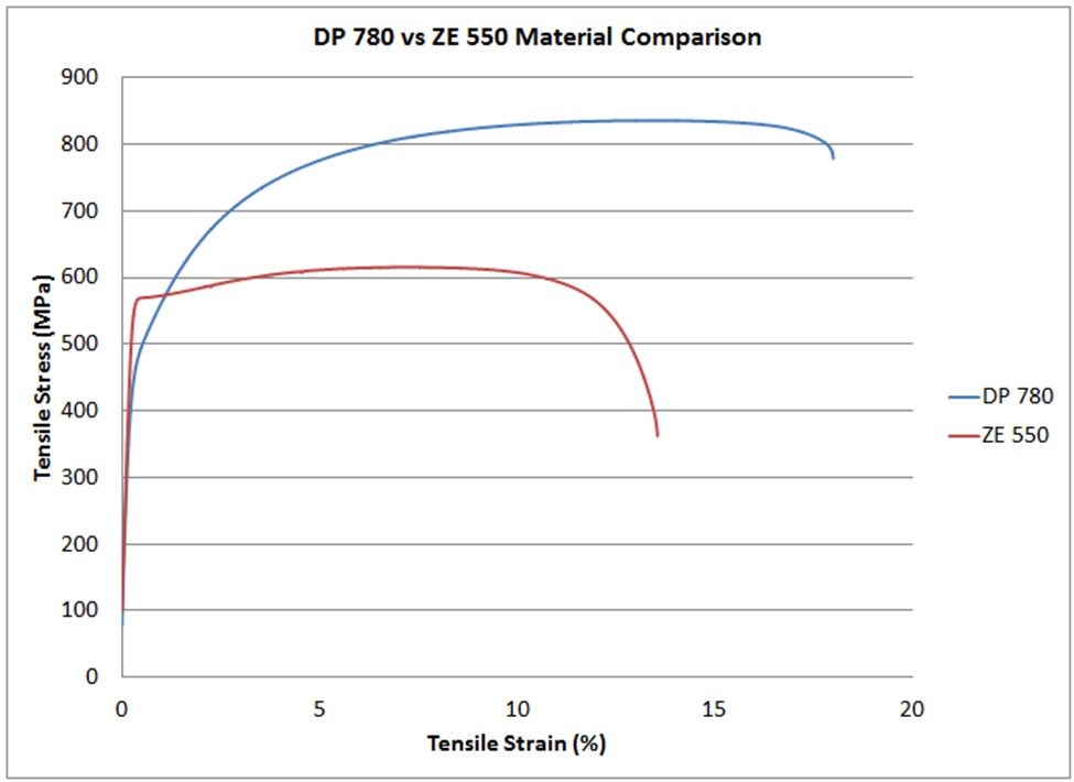
Figure 2 – Stress-strain curves for CR420Y780T-DP (blue) and ZE 550 (red). See text for description of the grades.
In conventional stamping operations, this work hardening is beneficial to delay the onset of necking. However, the use of dual-phase steels and other grades with high n-value can lead to dimensional issues in roll-formed parts. Flow stress in a given area is a function of the local strain. Each roll station induces additional strain on the overall part, and strains vary within the part and along the edge. This strength variation is responsible for differing springback and edge wave across a roll formed part.
Unlike conventional stamping, grades with a high yield/tensile ratio where the yield strength is close to the tensile strength are better suited to produce straight parts via roll forming.
Total elongation to fracture is the strain at which the steel breaks during tensile testing, and is a value commonly reported on certified metal property documents (cert sheets). As observed on the colloquially called “banana diagram”, elongation generally decreases as the strength of the steel increases.
For lower-strength steels, total elongation is a good indicator of a metal’s bendability. Bend severity is described by the r/t ratio or the ratio of the inner bend radius to the sheet thickness. The metal’s ability to withstand a given bend can be approximated by the tensile test elongation since, during a bend, the outermost fibers elongate like a tensile test.
In higher-strength steels where the phase balance between martensite, bainite, austenite, and ferrite plays a much larger role in developing strength and ductility than in other steels, microstructural uniformity usually limits bendability. Dual-phase steels, for example, have excellent uniform elongation and resistance to necking coming from the hardness difference between ferrite and martensite. However, this large hardness difference is also responsible for relatively poor edge stretchability and bendability. In roll-forming applications, those grades with a uniform microstructure will typically have superior performance. As an example, refer to Figure 2. The dual-phase steel shown in blue can be bent to a 2T radius before cracking, but the recovery annealed ZE 550 grade with noticeably higher yield strength and lower elongation can be bent to a ½T radius.
Remember that each roll-forming station only incrementally deforms the sheet, with subsequent stations working on a different region. Roll-formed parts do not need to use grades associated with high total elongation, especially since these typically have a bigger gap between yield and tensile strength.
We encourage you to visit https://ahssinsights.org/forming/roll-forming/roll-forming/ to learn more about roll forming and the types of coil shape that influence roll forming. Thank you to Brian Oxley and Dr. Daniel Schaeffler for providing this case study.

Brian Oxley, Product Manager, Shape Corporation, is a Product Manager in the Core Engineering team at Shape Corp. Shape Corp. is a global, full-service supplier of lightweight steel, aluminum, plastic, composite and hybrid engineered solutions for the automotive industry. Brian leads a team responsible for developing next generation products and materials in the upper body and closures space that complement Shape’s core competency in roll forming. Brian has a Bachelor of Science degree in Material Science and Engineering from Michigan State University.

Danny Schaeffler is the Metallurgy and Forming Technical Editor of the AHSS Applications Guidelines available from WorldAutoSteel. He is founder and President of Engineering Quality Solutions (EQS). Danny wrote the monthly “Science of Forming” and “Metal Matters” column for Metalforming Magazine, and provides seminars on sheet metal formability for Auto/Steel Partnership and the Precision Metalforming Association. He has written for Stamping Journal and The Fabricator, and has lectured at FabTech. Danny is passionate about training new and experienced employees at manufacturing companies about how sheet metal properties impact their forming success.
Blog, homepage-featured-top, Joining, Joining Dissimilar Materials, main-blog, News, Resistance Spot Welding, Resistance Welding Processes, RSW Modelling and Performance, RSW of Dissimilar Steel
This blog is a short summary of a published comprehensive research work titled: “Peculiar Roles of Nickel Diffusion in Intermetallic Compound Formation at the Dissimilar Metal Interface of Magnesium to Steel Spot Welds” Authored by Luke Walker, Carolin Fink, Colleen Hilla, Ying Lu, and Wei Zhang; Department of Materials Science and Engineering, The Ohio State University
*****
There is an increased need to join magnesium alloys to high-strength steels to create multi-material lightweight body structures for fuel-efficient vehicles. Lightweight vehicle structures are essential for not only improving the fuel economy of internal combustion engine automobiles but also increasing the driving range of electric vehicles by offsetting the weight of power systems like batteries.
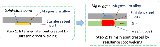
To create these structures, lightweight metals, such as magnesium (Mg) alloys, have been incorporated into vehicle designs where they are joined to high strength steels. It is desirable to produce a metallurgical bond between Mg alloys and steels using welding. However, many dissimilar metal joints form intermetallic compounds (IMCs) that are detrimental to joint ductility and strength. Ultrasonic interlayered resistance spot welding (Ulti-RSW) is a newly developed process that has been used to create strong dissimilar joints between aluminum alloys and high-strength steels. It is a two-step process where the light metal (e.g., Al or Mg alloy) is first welded to an interlayer (or insert) material by ultrasonic spot welding (USW). Ultrasonic vibration removes surface oxides and other contaminates, producing metal-to-metal contact and, consequently, a metallurgical bond between the dissimilar metals. In the second step, the insert side of the light metal is welded to steel by the standard resistance spot welding (RSW) process.
Cross-section View Schematics of Ulti-RSW Process Development
For resistance spot welding of interlayered Mg to steel, the initial schedule attempted was a simple single pulse weld schedule that was based on what was used in our previous study for Ulti-RSW of aluminum alloy to steel . However, this single pulse weld schedule was unable to create a weld between the steel sheet and the insert when joining to Mg. Two alternative schedules were then attempted; both were aimed at increasing the heat generation at the steel-insert interface. The first alternative schedule utilized two current pulses with Pulse 1, high current displacing surface coating and oxides and Pulse 2 growing the nugget. The other pulsation schedule had two equal current pulses in terms of current and welding time.
Lap shear tensile testing was used to evaluate the joint strength using the stack-up schematically, shown below. Note the images of Mg and steel sides of a weld produced by Ulti-RSW.
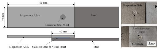 Lap Shear Tensile Test Geometry and the Resultant Weld Nuggets
An example of a welded sample showed a distinct feature of the weld that is comprised of two nuggets separated by the insert: the steel nugget formed from the melting of steel and insert and the Mg nugget brazed onto the unmelted insert. This feature is the same as that of the Al-steel weld produced by Ulti-RSW in our previous work. Although the steel nugget has a smaller diameter than the Mg nugget, it is stronger than the latter, so the failure occurred on the Mg sheet side.

Joint strength depends on several factors, including base metal strength, sheet thickness, and nugget size, making it difficult to compare how strong a weld truly is from one process to another. To better compare the dissimilar joints created by different processes, joint efficiency, a “normalized” quantity was calculated for various processes used for dissimilar joining of Mg alloys to steels in the literature, and those results, along with the efficiencies of Ulti-RSW with inserts, are shown together below. Most of the literature studies also used AZ31 as the magnesium base metal. The ones with high joint efficiency (about 53%) in the literature are resistance element welding (REW) and friction stir spot welding (FSSW). In our study, Ulti-RSW with SS316 insert was able to reach an excellent joint efficiency of 71.3%, almost 20% higher than other processes.
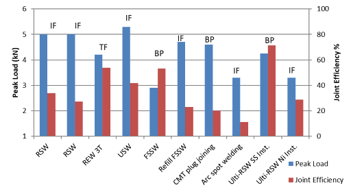 Process Evaluation and Comparison

Thanks are given to Menachem Kimchi, Associate Professor-Practice, Dept of Materials Science, Ohio State University, and Technical Editor – Joining, AHSS Application Guidelines, for this article.
Citations
H-66. G.T. Halmos (Editor) Roll Forming Handbook (1st ed.). CRC Press, 2005. doi.org/10.1201/9781420030693.
Citations
G.T. Halmos (Editor) Roll Forming Handbook (1st ed.). CRC Press, 2005.
doi.org/10.1201/9781420030693
Blog, homepage-featured-top, main-blog, News
WorldAutoSteel is focused on advancing steel’s advantages in the automotive, autonomous vehicle, and future mobility industries. To encourage careers in engineering, we are committed to engaging with future engineers at post-secondary education organizations around the globe. Our most recent engineering project, Steel E-Motive, was created to help the industry meet the challenges of future mobility and Level-5 autonomous vehicles and eventually reach net zero emissions targets.
We engaged Ricardo plc to collaborate with our technical directors to develop a Level 5 Autonomous Vehicle for the Steel E-Motive project. The project uncovered a few challenges that were solved by student engineering teams through Senior Capstone Projects. Here we summarize the Side Door and Door Hinges project, created at Michigan Technological University by the engineering students and faculty members listed herein.
Michigan Tech University – Senior Capstone Project #2: Adaptation of SEM2 from People Mover to Commercial Delivery Vehicle
MTU Senior Capstone Team: Kyle Davis, Nick Palatka, Evan Larson, Logan Pietila, Blake Pietila, Tej Bergin
Introduction and Background
This Senior Capstone Design Team was sponsored by WorldAutoSteel and Ricardo Engineering (UK engineering and consultancy firm) to develop a solution for expanding the serviceability within a 24-hour period for Steel E-Motive 2 (SEM2), their extra-urban electric autonomous vehicle concept.
The SEM2 vehicle is a stretched 6-passenger commuter targeting longer journeys with expanded occupancy or additional luggage capacity. In non-commuting hours, the Mobility Fleet Operator would like to continue revenue generation by quickly adapting the vehicle for commercial delivery services. Currently, occupant packaging contrasts with the storage requirements of a package delivery vehicle; thus, the SEM2 vehicles can only be utilized to either transport people or goods. Our project aims to develop interior seating that enables quick removal and adaptation to an optimal delivery van.
Project Details and Results of the Autonomous Vehicle Challenge
From the requirements outlined by WorldAutoSteel, the team focused further research on interior vehicle and seat design. Modern delivery methods, delivery vehicle layout, passenger vehicle seat safety requirements, and seat folding or locking mechanisms were sub-categories of research that hold value within the project’s scope. The main takeaways from our research include different pin and slot mechanisms that are incorporated into a preliminary design for a quick-release system. We also benchmarked a vertical folding seat based on International Harvester designs, and we have modified these for application to the SEM2 autonomous vehicle’s specific needs.
The quick-release system will benefit MSP technicians responsible for performing the conversion of multiple SEM2 vehicles in its fleet at their depot during off-commuting hours. In under 30 minutes, the fleet operators (MSP) must be able to convert the vehicle from a vehicle stressing passenger comfort to an autonomous delivery van and vice versa, using common tools and techniques while meeting all necessary safety standards and regulations. The fleet operators that provide the robotaxi service are not expected to see any major disruption in ride services; however, they may observe improved utilization and profitability if they use the vehicles for package delivery.
Our current engineering requirements include:
- Maximum total payload of 675 kg (6 passengers and 6 seats)
- Individual seat weight of 30kg (6 seats)
- Total volumetric storage space requirement of 1 cubic meter
- Total seating width equal to or less than 1220 mm
- Changeover time less than 30 minutes and
- Minimal number of changeover movements (Fewer than 50 for the complete conversion from passenger to cargo transportation)
Concept Solutions
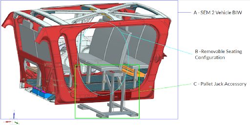
A graphical rendering of our selected system-level autonomous vehicle concept is provided in Figure 1. This design showcases two pairs of T-shaped rails placed in the fore-aft direction of the vehicle. These T-Rails are compatible with a slider system connecting to each seat leg’s bottom.
A sliced view of the rails and slider system are seen in Figure 2. On each slider, in the port-starboard direction, a circular slot approximately 20 mm in diameter (dependent on pin material and size) is cut-out to allow for the insertion of a spring-loaded steel pin. This pin engages both the slider and an equivalent slot cut into the rail, to allow the seat to be locked into a specified position along the rail (Figure 3). The rails run the full length of the vehicle’s interior, allowing 3 seating modules to be placed and locked into a position. Inserting and removing the slider on the rails will be possible through narrow sections where the slider can be vertically lifted or placed on the rail system.
In order to “drop the seats” onto the rails without manual lifting, the team has designed an accompanying “pallet jack accessory” that will be able to hold, transport, and lower the seating modules onto the rail system through the use of an industry-standard pallet jack with a lifting range of 6 inches. The pallet jack accessory can be seen in Figure 1, item C.
Figure 1 – System level concept – rapid adaptation of SEM2 to autonomous vehicle delivery services
The slider mechanism, seen in Figure 2 below, will house a ball roller bearing that allows for the translational motion along the rail to slide the seats into position.
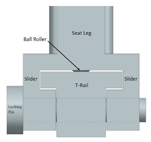
Figure 2 – Slider mechanism in Steel E-T-rail system
The roller bearing bolts into the slider mechanism allowing for fast and easy replacement. The T-Rails are then bolted to the structural members of the vehicle, where engineers from WorldAutoSteel have confidence the design can withstand any and all static and dynamic loading scenarios. The rails will feature a narrow section near the center, allowing the seating module to be removed. This narrow section is tapered to allow the slider to be “homed” and slid into its final, fixed position.
The arms of the pallet jack system reach out to allow a set of seats to be placed on the rail at one time. The pallet jack will drive through the open slots on the ground, lift the seats to the vehicle, align itself using markings on the vehicle, and drop the seats into the rails, where they can then be manually moved to their correct position. The system is designed to remove and insert these seats as fast as possible while exerting minimum effort that might stress the MSP technician. With ease of use and safety being the critical elements of every project, we’ve removed manual lifting from the equation and ensured a factor of safety of 2 is kept for all required crash loads under our current design.
Many integral components are COTS parts and can be bought in bulk to use for mass production as well as reserved parts, helping maintain low cost of ownership for the MSP. The components that are not COTS items, such as the rails and sliders, can be manufactured using high-volume, low-cost fabrication techniques such as stamping. Assembly of the system will be just as easy as all components are connected together using industry-standard fastening and welding techniques.
Conclusions
Validation – To confirm the ease of changeover and our objectives, a simulation was conducted to estimate the time and difficulty of changing from delivery service to people transporter. In a warehouse setting, a location was established as the “vehicle maintenance spot.” We developed a “seat module storage area” approximately 30 meters away. In this simulation, the following steps were conducted:
- A pallet jack was pre-staged near the vehicle, signaling the beginning of the conversion and timer
- A technician walked 30 m to the seating storage area and picked up the seats via accessory
- They carried seats back to the vehicle, aligned the pallet jack with the door, lowered seats onto the rail system, and removed the pallet jack accessory from the vehicle
- They slid the seats into the correct position and inserted the locking pin into its slot
This simulation was repeated twice to replicate the insertion of all six seats. To remove the seats, the steps would be reversed. After five runs of this simulation, ensuring adequate time to perform each simulated step, the average time to complete the simulation was 5 minutes 17 seconds with a total of 24 required movements.
These values were well within the 30-minute and 50-movement objectives. For further validation, we’ll repeat these simulations in the opposite direction, ie, removing the seats to transform into the delivery van. Finally, in Phase 2 of this project, we’ll continue to evaluate seat frame/track componentry to ensure robustness and durability in the proposed solutions.
More Info About Steel E-Motive
We are grateful to our student teams, their supportive leaders, and the universities providing automotive engineering education to our future industry leaders. Their contributions to Steel EMotive have been invaluable.
Interested in learning more about Steel E-Motive and the infinite tunability of steel for Future Mobility? Download the full engineering report here: Steel E-Motive Engineering Report