Automotive Welding Process Comparison, Blog, Joining
Car body-in-white (BIW) structures, such as pillars and rails, are increasingly made of complex stack-ups of advanced high-strength steels (AHSS) for vehicle lightweighting to achieve improved fuel efficiency and crashworthiness. Complex stack-ups comprise more than two sheets with similar/dissimilar steels and non-equal sheet thicknesses.
Resistance spot welding (RSW) of complex stack-ups can be challenging, especially when a thin sheet of low-strength steel is attached to multiple thick AHSS sheets with a thickness ratio of five or higher (thickness ratio = total thickness of the stack-up/thickness of the thinnest sheet). In such a case, the heat loss is much faster on the thin sheet side than on the thick sheet side, and consequently, obtaining sufficient penetration into the thin sheet without expulsion on the thick sheet side can be challenging.
An example of two automotive applications involving complex AHSS steel stack-ups is shown below.
Examples of automotive applications involving complex AHSS steel stack-ups
For welding 2T steel stack-ups, the weld schedule may be relatively simple and utilize just one current pulse with a specific weld time. However, typical RSW machines and controllers can customize and precisely control each parameter indicated in Figure 1.
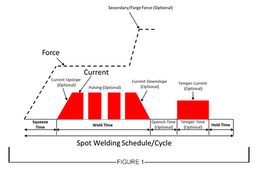
Figure 1: General Description of Resistance Spot Welding Schedule
For RSW 3T and 4T applications, more advanced schedules are needed to achieve good weld nugget penetration through all the interfaces in the stack-up. To achieve this objective, the use of multiple current pulses with short cool time in between the pulses showed to be most effective, and in some cases, the application of a secondary force showed to be beneficial.
Figure 2 describes a method for joining the 3T stack-up using two current pulses. The first one is a short-time pulse that does not allow enough time for the electrode cooling to dominate at the top sheet, so a weld can easily form between the top and middle sheet. Once that nugget has formed, the second pulse utilizes a lower current and longer time to form the second nugget, which then grows into the first nugget to form a single weld.
This approach can be also used with electrode force variation during the welding cycle to provide additional control of the contact resistances, but of course, it is limited to machines that are capable of varying force during the weld cycle.
Typical pulse times are 50 – 350 ms with cool times of 20 – 35 ms and current levels between 8 – 15 KA, depending on materials type and thickness.
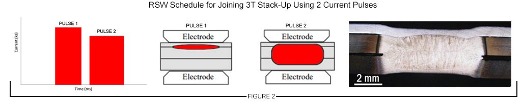
Figure 2: Example of RSW Schedule for Joining 3T Stack-Up Using 2 Current Pulses
A 4T stack-up example is shown in Figure 3. In this case, a similar approach was used with three current pulses applied during the weld cycle to produce a weld through all interfaces.
The common theme in resistance spot welding all complex stack-ups is using a complex, multi-pulse weld cycle. These more complex schedules should be developed experimentally and potentially with computational modeling. Another consideration that may be beneficial in some cases is to vary the top and bottom electrode face diameter, such as that the smaller electrode face is on the thinner material side of the stack-up.
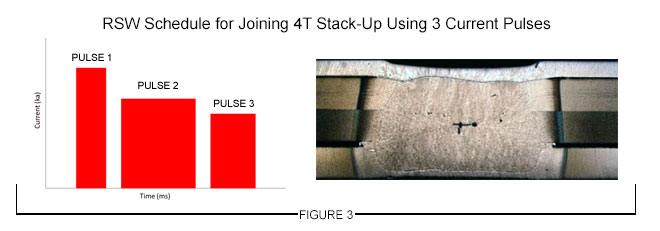
Figure 3: Example of an RSW Schedule for Joining 4T Stack-Up Using 3 Current Pulses

Thanks is given to Menachem Kimchi, Associate Professor-Practice, Dept of Materials Science, Ohio State University and Technical Editor – Joining, AHSS Application Guidelines, for this article.
homepage-featured-top, main-blog
In this edition of AHSS Insights, George Coates and Menachem Kimchi get back to basics with important fundamentals in forming and joining AHSS.
As the global steel industry continues its development of Advanced High-Strength Steels (AHSS), including 3rd Gen products with enhanced formability, we’re reminded that successful application is still dependent on the fundamentals, both in forming and joining. In this blog article, we address some of those forming considerations, as well as highlighting common joining issues in manufacturing.
Forming Considerations
The somewhat lower formability of AHSS compared to mild steels can almost always be compensated for by modifying the design of the component and optimizing blank shape and the forming process.
In stamping plants, we’ve observed inconsistent practices in die set-up and maintenance, surface treatments and lubrication application. Some of these inconsistencies can be addressed through education, via training programs on AHSS Application Guidelines. These Guidelines share best practices and lessons learned to inform new users on different behaviors of specific AHSS products, and the necessary modifications to assist their application success. In addition to new practices, we’ve learned that applying process control fundamentals become more critical as one transitions from mild steels to AHSS, because the forming windows are smaller and less forgiving, meaning these processes don’t tolerate variation well. If your present die shop is reflective of housekeeping issues, such as oil and die scrap on the floor or die beds, you are a candidate for a shop floor renovation or you will struggle forming AHSS products.
Each stamping operation combines three main elements to achieve a part meeting its desired functional requirements:
There is good news, in that our industry is responding with new products and services to improve manufacturing performance and save costs.
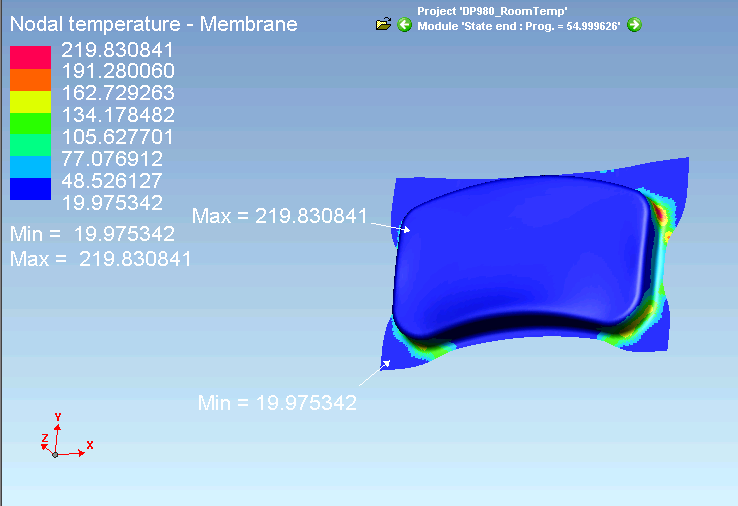
As an example, lubrication application is often overlooked, and old systems may be ineffective. In the forming of AHSS, part temperatures can become excessive, and break down lubricant performance. Figure 1 shows an example of part temperatures from an Ohio State University study conducted with DP 980 steels.O-1
Figure 1: Example Temperature distribution for DP 980 Steel.O-1
Stampers often respond by “flooding” the process with extra lubricant, thinking this will solve their problem. Instead, lubricant viscosity and high temperature stability are the most important considerations in the lubricant selection, and new types exist to meet these challenges. Also, today there are new lubrication controllers that can finely control and disperse wet lubricants evenly across the steel strip, or in very specific locations, if forming requirements are localized. These enable better performance while minimizing lubricant waste (saving cost), a win-win for the pressroom.
Similarly, AHSS places higher demands on tool steels used in forming and cutting operations. In forming applications, galling, adhesive wear and plastic deformation are the most common failure mechanisms. Surface treatments such as PVD, CVD and TD coatings applied to the forming tool are effective at preventing galling. Selection of the tool steel and coating process used for forming AHSS will largely depend on the:
- Strength and thickness of the AHSS product,
- Steel coating,
- Complexity of the forming process, and
- Number of parts to be produced.
New die materials such as “enhanced D2” are available from many suppliers. These improve the balance between toughness, hardness and wear resistance for longer life. These materials can be thru-hardened, and thus become an excellent base material for PVD or secondary surface treatments necessary in the AHSS processing. And new tool steels have been developed specifically for hot forming applications.
Joining Considerations
In high-volume production different Resistance Spot Welding (RSW) process parameters can be used depending on the application and the specifications applied. Assuming you chose the appropriate welding parameters that allows for a large process window, manufacturing variables may ruin your operation as they strongly effect the RSW weld quality and performance.
Material fit-up
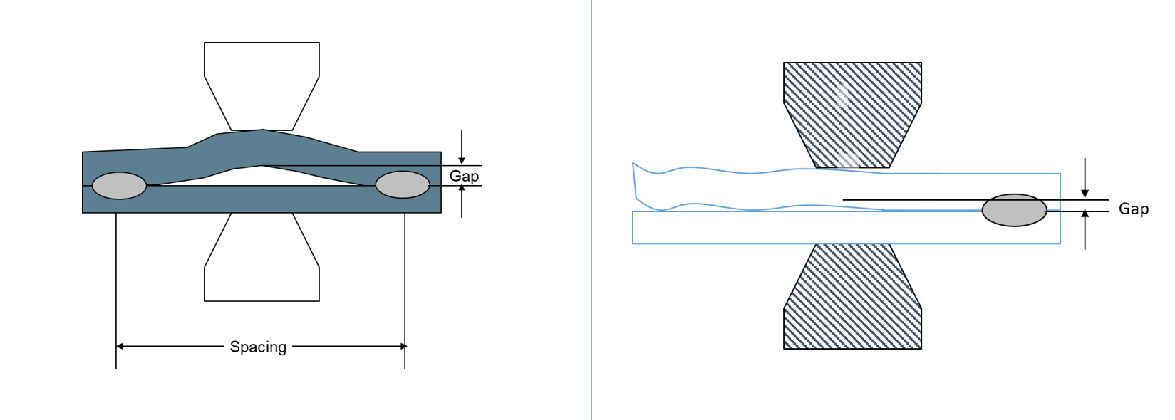
One of the great advantages of the RSW process is the action of clamping the material together via the electrode force applied during the process. However due to the pre-welding condition/processing such as the stamping operation, this fit-up issue, as shown in Figure 2, can be very significant especially in welding an AHSS product. In this case the effective required force specified during the process setup for the application is significantly reduced and can result in an unacceptable weld, over-heating, and severe metal expulsion. If the steels are coated, higher probability for Liquid Metal Embrittlement (LME) cracking is possible.

Figure 2: Examples of Pre-Welding Condition/Processing Fit-Up Issues.
For welding AHSS, higher forces are generally required as a large part of the force is being used to force the parts together in addition to the force required for welding. Also, welding parameters may be set for pre-heating with lower current pulses or current up-slope to soften the material for easier material forming and to close the gap.
Electrodes Misalignment
During machine set up, the RSW electrodes need to be carefully aligned as shown in Figure 3A. However, in many production applications, electrode misalignment is a common problem.
Electrode misalignment in the configurations shown in Figure 3B may be detrimental to weld quality of any RSW application. Of course, the electrode misalignment shown in this figure is exaggerated but the point is that it happens frequently on manufacturing welding lines.
In these cases, the intendent contact between the electrodes is not achieved and thus the current density and the force density (pressure) required for producing an acceptable weld cannot be achieved. With such conditions, overheating, expulsion, sub-size welds and extensive electrode wear will result. Again, if coated steels are involved, the probability for LME cracking is higher.
Note also that following specifications or recommendations for water cooling the electrode is always important for process stability and extending electrode life.
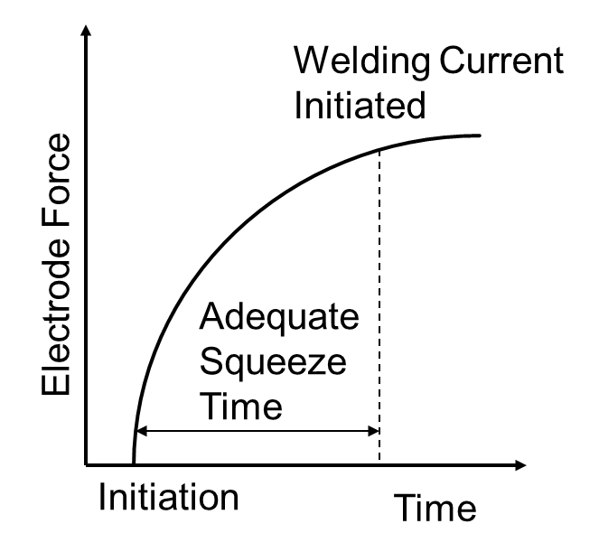
Figure 4: Sequence of Squeeze Time and Welding Current Initiation.
Squeeze Time
The squeeze time is the time required for the force to reach the level needed for the specific application. Welding current should be applied only after reaching this force, as indicated in Figure 4. All RSW controllers enable the easy control of squeeze time, just as with the weld time, for example. In many production operations, a squeeze time is used that is too low due to lack of understanding of its function. If squeeze time is too low, high variability in weld quality in addition to severe expulsion will be the result.
The squeeze time required for an application depends on the machine type and characteristics (not an actual welding parameter such as weld time or welding current for example).
Some of the more modern force gauges have the capability to produce the curve shown in the Figure so adequate squeeze time will be used. If you do not know what the required squeeze time for your machine/application is, it is recommended to use a longer time.
For more on these topics, browse the Forming and Joining menus of these Guidelines.