homepage-featured-top, main-blog, News
There is interest in the sheet metal industry on how to adopt Industry 4.0 into their legacy forming practices to significantly improve productivity and product quality. Figure 1 illustrates four important variables influencing part quality: material properties, die friction response, elastic deflection of the tool, and press dynamic characteristics. These variables are usually difficult to measure or track during the production runs. When these variables significantly influence the part quality and the scrap rate increases, the operators manually adjust the forming press parameters (speed and pressure), lubricant amount, and tooling setup. However, these manual adjustments are not always possible or effective and can be costly for the increased part complexity.

Figure 1: Important variables influencing the stamping quality.H-35
The ultimate vision for Industry 4.0 in sheet metal forming is an autonomous forming process with maximum process efficiency and minimum scrap rate. This is very similar to the full self-driving (FSD) vision of the electric vehicle today. This will be valuable for the automotive industry that has to process large production volumes with various steel grades.
For example, normal variations of the incoming material properties for Advanced High-Strength Steel (AHSS) may have a significant effect on part quality associated with necking, wrinkling, and cracking, which in turn drastically increases the production cost. This variation of the incoming material properties increases uncertainty in sheet metal forming by making consistent quality more challenging to achieve, thereby increasing the overall manufacturing cost. A nondestructive evaluation (NDE) can be a useful tool to measure incoming material properties.
There are several types of NDE sensors. Most of the sensors need further development or are not suitable for production applications. However, some of the NDE sensors, such as the eddy current tools, laser triangulation sensors equipment, and equipment developed by Fraunhofer IZFP called 3MA (micromagnetic, multiparametric microstructure, and stress analysis), have already been applied to a few limited production applications. These sensors can be used to provide data during production to select the optimal parameters. They also can be used to obtain material properties for finite element model (FEM) analysis. Studies in deep drawing of a kitchen sink production used a laser triangulation sensor to measure the sheet thickness and an eddy-current sensor to measure the yield strength, tensile strength, uniform elongation, elongation to break, and grain size of the incoming material. The material data is used as an input for simulations to generate the metamodels to determine the process window, and it is used as an input for the feed-forward control during the process.K-27
Figure 2 shows how NDE tools are used for feed-forward controls and cameras for feedback control to determine the optimum press setting on sink forming production.

Figure 2: Process control for sheet metal forming of kitchen sink production.H-36
Another study proposed the use of Fraunhofer’s 3MA equipment to determine the mechanical properties of incoming blanks for a sheet forming process. The 3MA sensor correlates the magnetic properties of the material with the mechanical properties and calibrates the system with the procedure outlined in Figure 3. The study showed a good correlation between the measurements from the sensor and the tensile testing results; however, the sensor should be calibrated for each material. Also, the study proposed to use a machine-learning algorithm instead of a feed-forward control to predict the most effective parameters during the drawing process.K-28

Figure 3: Calibration procedure for 3MA sensors.K-28
Technologies associated with Industry 4.0 have a natural fit with AHSS. The advanced slide motion capabilities of servo presses combined with active binder force control can be paired with stamping tonnage and edge location measurements from every hit to create closed-loop feedback control. With press hardening steels (PHS), vision sensors and thermal cameras can be used for controlling the press machine and transfer system.
Have a look at the Dr. Kim’s detailed article on Industry 4.0 for more examples of NDE sensors, as well as information on applying Industry 4.0 to forming process controls.
![Defining Steels]()
Metallurgy
Basis
There are different ways to classify automotive steels. One is a metallurgical designation providing some process information. Common designations include lower-strength steels (interstitial-free and mild steels); conventional high strength steels, such as bake hardenable and high-strength, low-alloy steels (HSLA); and Advanced High-Strength Steels (AHSS) such as dual phase and transformation-induced plasticity steels. Additional higher strength steels include press hardening steels and steels designed for unique applications that have improved edge stretch and stretch bending characteristics.
A second classification method important to part designers is strength of the steel. This document will use the general terms HSLA and AHSS to designate all higher strength steels. The principal difference between conventional HSLA steels and AHSS is their microstructure. Conventional HSLA steels are single-phase ferritic steels with a potential for some pearlite in C-Mn steels. AHSS are primarily steels with a multiphase microstructure containing one or more phases other than ferrite, pearlite, or cementite – for example martensite, bainite, austenite, and/or retained austenite in quantities sufficient to produce unique mechanical properties. Some types of AHSS have a higher strain hardening capacity resulting in a strength-ductility balance superior to conventional steels. Other types have ultra-high yield and tensile strengths and show a bake hardening behavior.
AHSS include all martensitic and multiphase steels having a minimum specified tensile strength of at least 440 MPa. Those steels with very high minimum specified tensile strength are sometimes referred to as Ultra High Strength Steels (UHSS). Several companies choose 980 MPa as the threshold where “Ultra” high strength begins, while others use higher thresholds of 1180 MPa or 1270 MPa. There is no generally accepted definition among the producers or users of the product. The difference between AHSS and UHSS is in terminology only – they are not separate products. The actions taken by the manufacturing community to form, join, or process is ultimately a function of the steel grade, thickness, and mechanical properties. Whether these steels are called “Advanced” or “Ultra” does not impact the technical response.
Third Generation, or 3rd Gen, AHSS builds on the previously developed 1st Gen AHSS (DP, TRIP, CP, MS, and PHS) and 2nd Gen AHSS (TWIP), with global commercialization starting around 2020. 3rd Gen AHSS are multi-phase steels engineered to develop enhanced formability as measured in tensile, sheared edge, and/or bending tests. Typically, these steels rely on retained austenite in a bainite or martensite matrix and potentially some amount of ferrite and/or precipitates, all in specific proportions and distributions, to develop these enhanced properties.
Nomenclature
Historically, HSLA steels were described by their minimum yield strength. Depending on the region, the units may have been ksi or MPa, meaning that HSLA 50 and HSLA 340 both describe a High Strength Low Alloy steel with a minimum yield strength of 50 ksi = 50,000 psi ≈ 340 MPa. Although not possible to tell from this syntax, many of the specifications stated that the minimum tensile strength was 70 MPa to 80 MPa greater than the minimum yield strength.
Development of the initial AHSS grades evolved such that they were described by their metallurgical approach and minimum tensile strength, such as using DP590 to describe a dual phase steel with 590 MPa tensile strength. Furthermore, when Advanced High Strength Steels were first commercialized, there was often only one option for a given metallurgical type and tensile strength level. Now, for example, there are multiple distinct dual phase grades with a minimum 980 MPa tensile strength, each with different yield strength or formability.
To highlight these different characteristics throughout this website, each steel grade is identified by whether it is hot rolled or cold rolled, minimum yield strength (in MPa), minimum tensile strength (in MPa), and metallurgical type. Table 1 lists different types of steels.

Table 1: Different Types of Steels and Associated Abbreviations.
As an example, CR-500Y780T-DP describes a cold rolled dual phase steel with 500 MPa minimum yield strength and 780 MPa minimum ultimate tensile strength. There is also another grade with the same minimum UTS, but lower yield strength: CR440Y780T-DP. If the syntax is simply DP780, the reader should assume either that the referenced study did not distinguish between the variants or that the issues described in that section applies to all variants of a dual phase steel with a minimum 780 MPa tensile strength.
Another syntax issue is the presentation of the strength (yield or tensile), and whether it is rounded to the nearest 10 or 50 MPa. For example, consider DP980 compared with DP1000. Both forms represent essentially the same grade. In Europe, this steel may be described as having a tensile strength of 100 kgf/mm2, corresponding to 981 N/mm2 (981 MPa), and expressed as DP980. In Asia, the steel may be referred to as 100K (an abbreviation for 100 kgf/mm2). In other parts of the world, it may be rounded to nearest 50 MPa, as DP 1000. This naming approach applies to many grades, with some shown in Table 2. In some cases, although the OEM specification may list the steel as DP800 (for example), the minimum tensile strength requirement may still be 780 MPa. Furthermore, independent of the chosen naming syntax, the steel company will supply to the actual specification requirements, and will use different process controls to meet a 780 MPa minimum compared with an 800 MPa minimum.
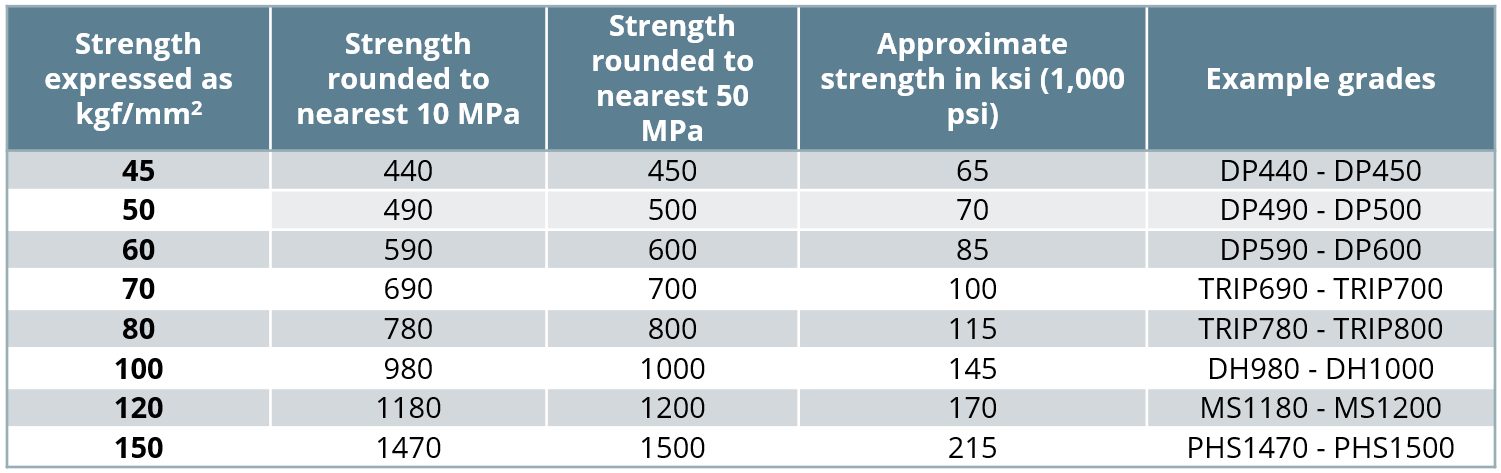
Table 2: Syntax Related to AHSS Strength Levels
Press hardening steels sometimes require a different syntax. Some OEMs will use a similar terminology as described above. For example: CR-950Y1300T-PH (PH stands for Press Hardenable or Press Hardened) or CR-950Y1300T-MB (MB stands for Manganese-Boron steel) can describe the same cold rolled press hardening steel with 950 MPa minimum yield strength and 1300 MPa minimum tensile strength after completing the press hardening operation. Other specifications may show suffixes which highlight the forming process used, such as -DS for direct hot stamping, -IS for indirect hot stamping and MS for a multi-step process. Furthermore, sources may describe this product focused on its typical tensile strength as PHS1500T. The abbreviation PQS (Press Quenched Steel) is typically used for grades that do not harden after hot stamping. These may be noted as PQS450 and PQS550, where the numbers stand for the approximate minimum tensile strength after the hot stamping cycle (see the section on Grades With Higher Ductility on the linked page).
Graphical Presentation
Generally, elongation (a measure of ductility) decreases as strength increases. Plotting elongation on the vertical axis and strength on the horizontal axis leads to a graph starting in the upper left (high elongation, lower strength) and progressing to the lower right (lower elongation, higher strength). This shape led to the colloquial description of calling this the banana diagram.

Figure 1: A generic “banana” diagram comparing strength and elongation.
With the continued development of advanced steel options, it is no longer appropriate to describe the plethora of options as being in the shape of a banana. Instead, with new grades filling the upper right portion (see Figure 2), perhaps it is more accurate to describe this as the football diagram as the options now start to fall into the shape of an American or Rugby Football. Officially, it is known as the steel Global Formability Diagram.
Even this approach has its limitations. Elongation is only one measure of ductility. Other ductility parameters are increasingly important with AHSS grades, such as hole expansion and bendability. BillurB-61 proposed a diagram comparing the bend angle determined from the VDA238-100 testV-4 with the yield strength for various press hardened and press quenched steels.

Figure 3: VDA Bending Angle typically decreases with increasing yield strength of PHS/PQS grades.B-61
Figure 4 shows a local/global formability map sometimes referred to as the Hance Diagram named after the researcher who proposed it.H-16 This diagram combines measures of local formability (characterized by true fracture strain) and global formability (characterized by uniform elongation), providing insight on different characteristics associated with many steel grades and helping with application-specific material grade selection. For example, if good trim conditions still create edge splits, selecting materials higher on the vertical axis may help address the edge-cracking problems. Likewise, global formability necking or splitting issues can be solved by using grades further to the right on the horizontal axis.

Figure 4: The Local/Global Formability Map combines measures of local formability (true fracture strain) and global formability (uniform elongation) to highlight the relative characteristics of different grades. In this version from Citation D-12, the colors distinguish different options at each tensile strength level.
Grade Portfolio
Previous AHSS Application Guidelines showcased a materials portfolio driven by the FutureSteelVehicle (FSV) program, with more than twenty new grades of AHSS acknowledged as commercially available by 2020. The AHSS materials portfolio continues to grow, as the steel industry responds to requirements for high strength, lightweight steels. Table 3 reflects available AHSS grades as well as grades under development and nearing commercial application. The Steel Grades page provides details about these grades and their applications.

Table 3: Commercially available AHSS Grades and grades under development for near-term application. Grade names shown in Italicized Bold were available in FutureSteelVehicle. For all but PQS/PHS, Grade Name indicates the minimum yield strength, minimum tensile strength, and the type of AHSS. The min EL column indicates a typical minimum total elongation value, which may vary based on test sample shape, gauge length, and thickness. PQS/PHS grade name indicates nominal tensile strength.
Global automakers create steel specification criteria suited for their vehicle targets, manufacturing infrastructure, and other constraints. Although similar specifications exist at other companies, perfect overlap of all specifications is unlikely. Global steelmakers have different equipment, production capabilities, and commercial availability.
Minimum or typical mechanical properties shown on this web page and throughout this site illustrates the broad range of AHSS grades that may be available. Properties of hot rolled steels can differ from cold rolled steels. Coating processes like hot dip galvanizing or galvannealing subjects the base metal to different thermal cycles that affect final properties. Test procedures and requirements have a regional or OEM influence, such as preference to using tensile test gauge length of 50 mm or 80 mm, or specifying minimum property values parallel or perpendicular to the rolling direction.
Steel users must communicate directly with individual steel companies to determine specific grade availability and the specific associated parameters and properties, such as:
- Chemical composition specifications,
- Mechanical properties and ranges,
- Thickness and width capabilities,
- Hot-rolled, cold-rolled, and coating availability,
- Joining characteristics.
Tailored Products
topofpage
Types of Tailored Products
Key materials characteristics for formed parts include strength, thickness, and corrosion protection. Tailored products provide opportunities to place these attributes where they are most needed for part function, and remove weight that does not contribute to part performance.
Welded Tailored Blanks (Tailor Welded Blanks)
Welded tailored blanks are a type of tailored product, as are patchwork blanks, tailor welded coils, tailor rolled coils, tailor rolled tubes and tailor welded tubes.
Laser welding is the most common approach to creating these products, but other options like resistance mash seam welding are possible. Mash seam welding requires that the blanks overlap, which adds mass. The heat affected zone (HAZ) for mash seam welds is considerably larger than that of laser welds. Compared with laser welding, the temperature reached when resistance mash seam welding is lower. This may improve formability due to reduced martensite formation, but the larger HAZ and thicker joint may negate this benefit. Non-linear welds are more challenging to produce with the mash seam approach. Welded Tailored Blanks refers to blanks made via either laser welding or mash seam welding. The following discussion centers on blanks and coils joined by lasers.
Butt-welding two or more flat sheets into a single blank creates a laser welded tailored blank (LWTB), also known as a tailor welded blank or laser welded blank (LWB). Steel grades and thickness may be (and usually are) different in the component sheets. Corrosion protection strategies may be different on each component of the welded blank. “Sub blanks” is another name for these component sheets.
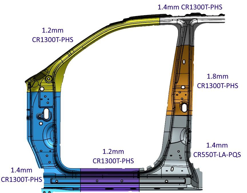
Figure 1 shows a laser welded door ring with multiple grades and thicknesses. This technology allows for a reduction in panel thickness in non-critical areas, thus contributing to an overall mass reduction of the part. The lower strength product in the bottom section of the B-Pillar helps dissipate the crash energy in the event of a side impact, playing a key role in crash energy management.
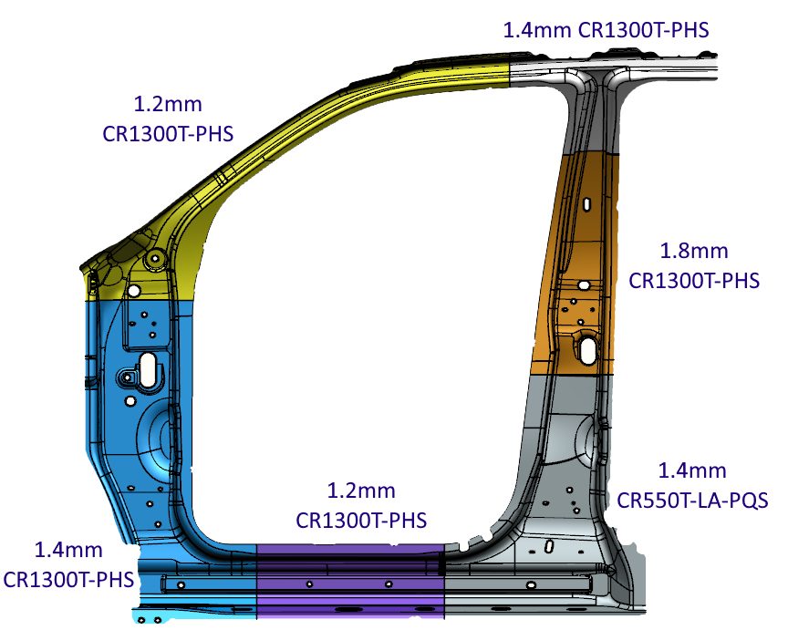
Figure 1: Six-piece Laser Welded Tailored Blank with multiple grades and thickness.R-3
Patchwork Blank
An alternate approach to a laser welded tailored blank involves the creation of what is known as a patchwork blank, consisting of two or more blanks potentially having different thickness or grades. The unique characteristic is that the blanks are placed one on top of the other and (typically) spot welded together while still flat. The patched blank requires only one stamping operation, eliminating the need to join them after forming the components separately. This approach is satisfactory for both cold stamping and hot stamping. The correct number of spot-welds is important in terms of cost and safety. Furthermore, if the components shift relative to one another during the forming operation, the spot welds may shear. There is excellent fit between both parts after forming, allowing for easy application of additional spot welds if needed. Part size, the number and location of reinforcements, and available infrastructure are among the key considerations in deciding between a laser welded or patch blank approach. For example, patchwork blanks may be preferred if the reinforced area is relatively small with complex contours or located within the boundaries of the main blank.
Tailor Welded Coils
Rather than building blanks from individual components, a similar approach is to join entire coils together, edge to edge. These tailor welded coils (Figure 2) are used in coil-fed processes such as blanking, progressive die stamping, transfer press stamping, and roll forming operations. The basic process takes separate coils, prepares their edges for contiguous joining, and laser welds these together into one master coil. The new strip is either directly blanked or re-coiled for future blanking or use as feedstock for a continuous coil-fed stamping or roll forming line (Figure 3). Variations in strength, thickness, and coating occur across the width.
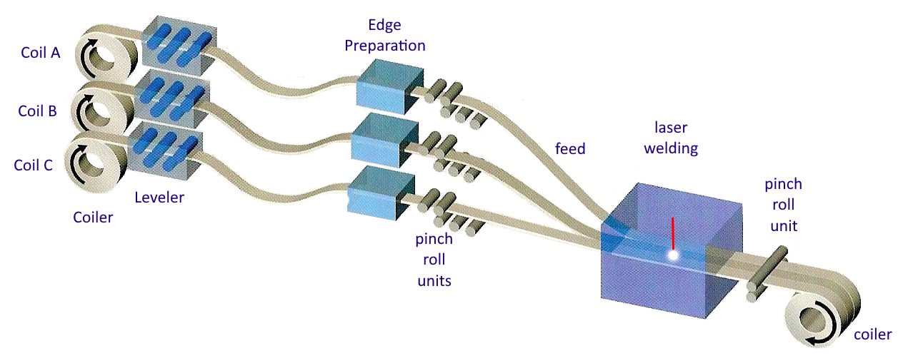
Figure 2: Production Process of Tailor Welded Coils.S-28
![Figure 3: General usage of Tailor Welded Coils [S-28]](https://ahssinsights.org/wp-content/uploads/2020/07/tailor-welded-cole-common-use.jpg)
Figure 3: General usage of Tailor Welded Coils.S-28
Tailor Rolled Coils
Whereas tailor welded coils can vary in properties across the coil width, tailor rolled coils have variable thickness down the length of the coil. Production facilities for tailor rolled coils vary the gap between the rolls used for thickness reduction, allowing for different strip thicknesses in the direction of rolling (Figure 4). Accurate measuring and feedback control technology guarantees the strip thickness tolerances. A significant advantage to this approach results from the transition from one thickness to another with no joints or discontinuities, providing an efficient load path without stress risers. A tailor rolled coil can be either used for blanking operations (for stamping or tubular blanks), or as feedstock into a roll forming line.
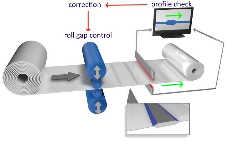
Figure 4: Tailor Rolled Coils vary in thickness down the length of the coil.Z-5
After cold rolling to achieve the targeted thickness variation, coils are annealed to reset the mechanical properties. Tensile properties can be uniform in the blank, with only the thickness varying. Tailored properties are generated by adjusting the incoming coil thickness and the associated thickness reductions, leading to different degrees of recrystallization occurring in the annealing step.Z-14 TRBs used in press hardening do not need to be annealed first, and tailored properties can be produced with the appropriate PHS process.
Tailor Rolled Tubes
Tailor rolled coils are the feedstock to produce variable thickness tailor rolled tubes.
Tailor Welded Tubes
Conventional tube production involves roll forming strips to the desired shape and welding the free ends together to create a closed section. A tailor welded tube production process allows the designer to create complex variations in shape, thickness, strength, and coating (Figure 5)
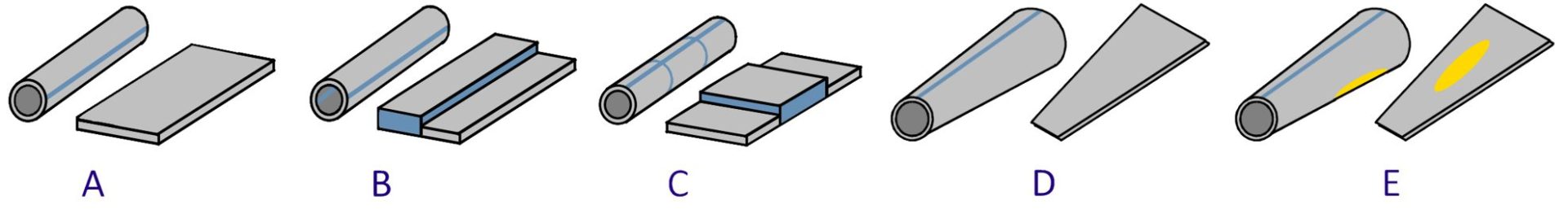
Figure 5: Tailored tube production allows for differing thickness and strength within the same tube. A) 1-piece cylindrical tube with monolithic properties; B and C) 2-piece tailored tube with property variation down the length of the tube; D) 1-piece conical tube; E) 2-piece conical tube with a patchwork blank.
With hydroforming technology, the next step in tubular components is to bring the sheet metal into a shape closer to the design of the final component without losing tailored blank features (Figure 6).
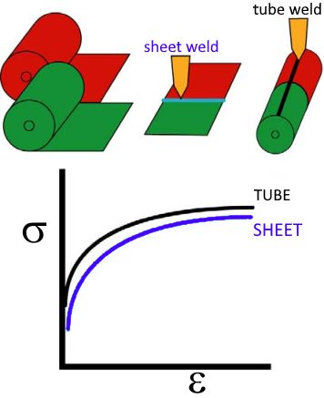
Figure 6: Mechanical properties of tailored tubes are close to the original metal properties in the sheet condition. Hydroforming changes the properties based on the local deformation.G-8
Hydroformed conical tailored tubes offer automotive body engineers an additional approach to crash energy management while achieving a lightweight design. In frontal crash and side impacts the load paths have a key importance on the body design as they have a major bearing on the configuration of the structural members and joints. Figure 7 shows an example of a front-rail hydroformed prototype. The conical tailored tubes for this purpose take advantage of the high work hardening potential of TRIP steel.
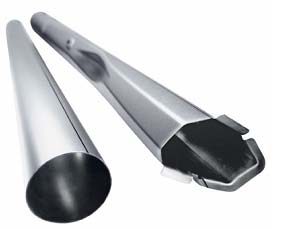
Figure 7: Front-rail prototype based on a conical tube having 40 mm end to end difference in diameter.F-3
Benefits of Tailored Products in Automotive Body Construction
Figure 8 highlights some of the areas within the body structure where companies have considered transitioning to welded tailored blanks. Other tailored products may be suitable in other areas.
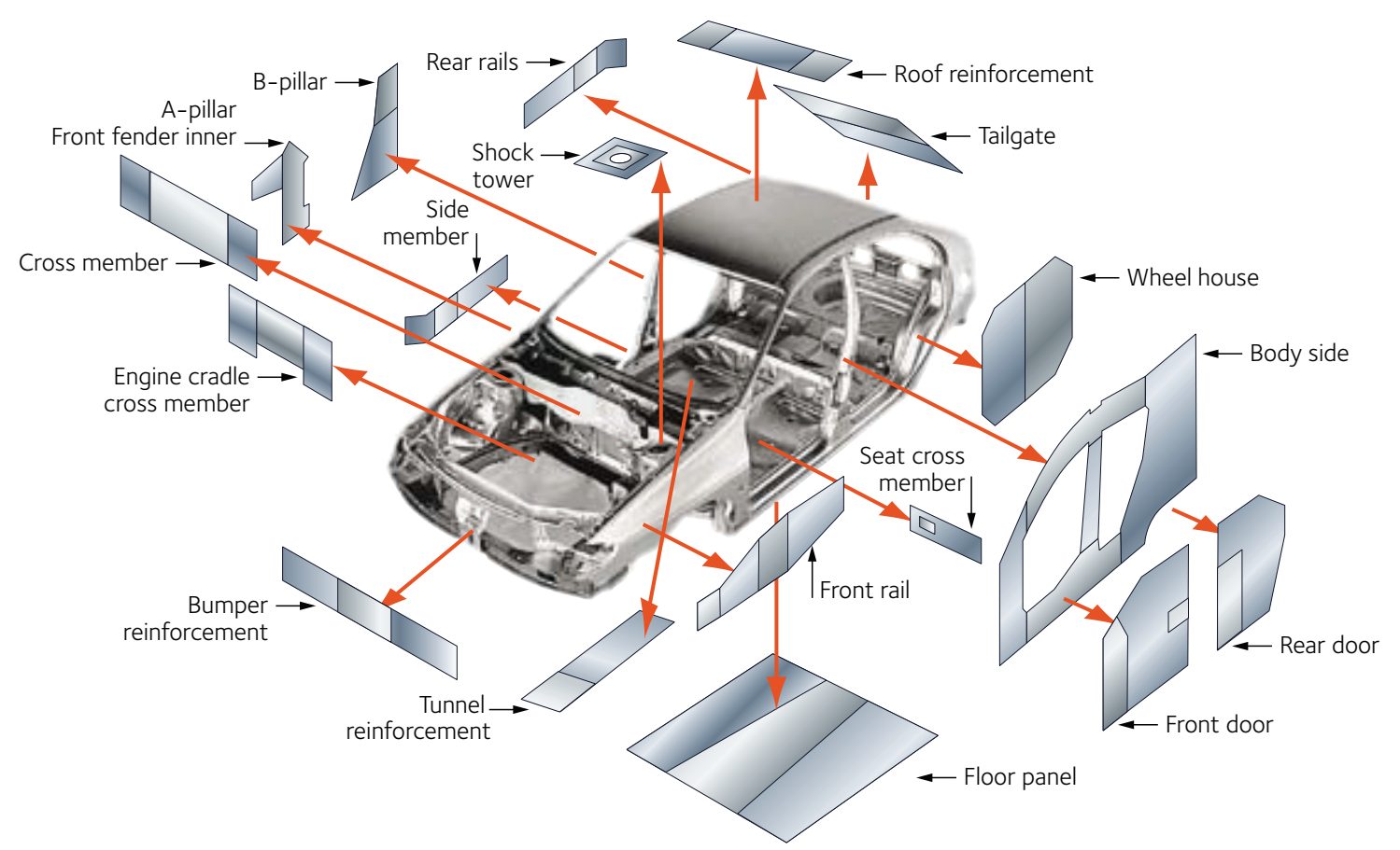
Figure 8: Applications suited for welded tailored blanks.A-31
Tailored products offer numerous advantages over the conventional approach involving the stamping and assembly of individual monolithic blanks which have a single grade, thickness, and coating, including:
Improved materials utilization
- Certain parts, like door rings (Figure 1), window frames, and door inner panels, have large cutout areas contributing to engineered scrap. Converting these to welded tailored blanks allows for optimized nesting of the individual components. Figure 9 presents an example of optimized nesting associated with body side aperture designs using a tailor welded blank. Reduced blank width requirements may allow for additional suppliers or use of master coils yielding slit mults. In the other extreme, blank dimensions larger than rolling mill capabilities are now feasible.
Elimination of reinforcement parts and reduced manufacturing infrastructure requirements
- In areas needing additional thickness for stiffness or crash performance, conventional approaches require stamping both the primary part and an additional smaller reinforcement and then spot welding the two parts together. The tailored product directly incorporates the required strength and thickness. Compared with a tailored product, the conventional approach requires twice the stamping time and dunnage, creates inventory, and adds the spot welding operation. Tolerance and fit-up issues appear when joining two formed parts, since their individual springback characteristics must be accommodated.
Part consolidation
- Similar to the benefits of eliminating reinforcements, tailored products may combine the function of what would otherwise be multiple distinct parts which would need to be joined.
Weight savings
- Conventional approaches to body-in-white construction requires individual parts to have flat weld flanges to facilitate spot welding. Combining multiple parts into a tailored product removes the need for weld flanges, and their associated weight.
Improved NVH, safety, and build quality
- Joining formed parts is more challenging than joining flat blanks first and then stamping. Tailored products have better dimensional integrity. Elimination of spot welds leads to a reduction in Noise, Vibration, and Harshness (NVH). A continuous weld line in tailored products means a more efficient load path.
Enhanced engineering flexibility
- Using tailored products provides the ability to add sectional strength in precise locations to optimize body structure performance.
Easily integrated with advanced manufacturing technologies for additional savings
- Tailored products incorporated into hot stamping or hydroforming applications magnify the advantages described here, and open up additional benefits.
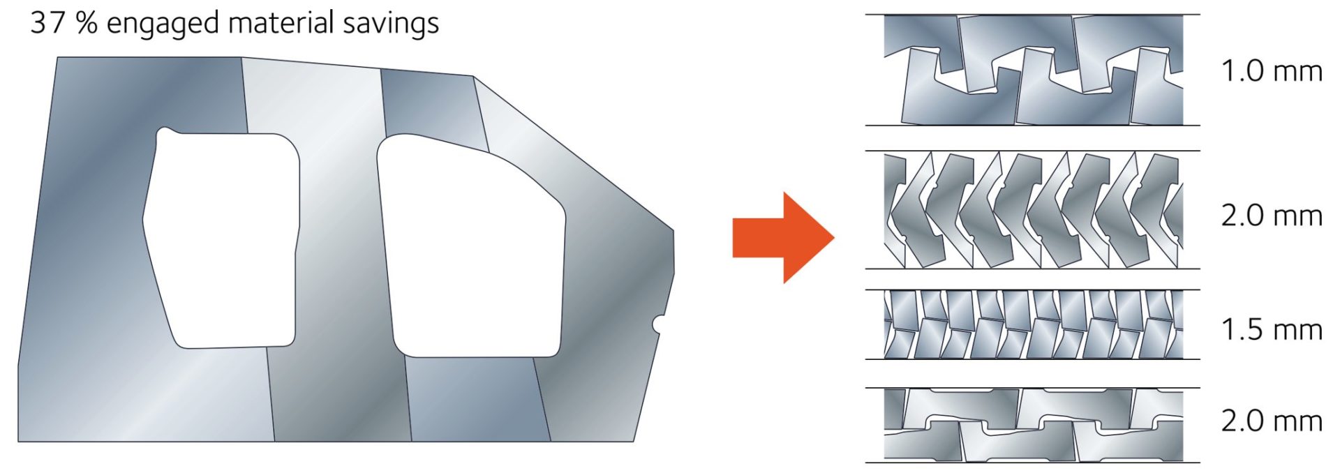
Figure 9: Nesting optimization dramatically reduces engineered scrap.A-31
Design, Usage, and Troubleshooting Guidance
Edge Quality of Component Blanks Used to Create the Welded Blank
Minimal burr, maximized sheared edge stretchability, and maximized tool life are characteristics of good sheared edge quality in conventional blanking operations. When creating sub-blanks for assembly into a laser welded tailored blank, there is an additional critical characteristic: squared edges with high straightness are a prerequisite to avoid local gaps between the blank edges causing undercut in the weld bead and the associated loss of mechanical properties (Figure 10). Conventional shearing operations produce the edge seen in Figure 10a. Precision die blanking with tight clearances, as well as laser blanking, produce edges suitable for the blank welding operation (Figure 10b). Another option is to use a conventional shearing approach to produce a slightly oversize blank, and then use precision shears as the first step in the laser welding line. The advantage to this approach minimizes the impact of edge damage which might occur during transportation.
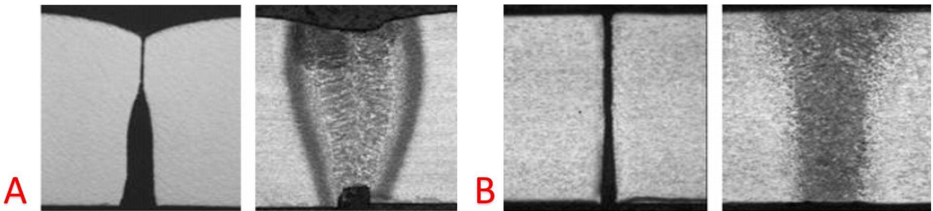
Figure 10: Edge condition and welding result. A) Poor edge resulting in increased residual butt gap and weld undercut; B) Optimum squared edge by precision die blanking or laser welding resulting in flush weld surfaces.S-29
Forming analysis of Welded Blanks
The weld joint and adjacent heat affected zone complicates the forming analysis of welded blanks. There are generally two scenarios that occur: failure perpendicular to the weld and failure parallel to the weld (Figure 10).
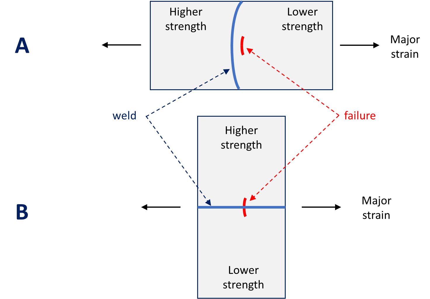
Figure 11: Major strain axis relative to weld line orientation. A) Weld line is perpendicular to the major strain axis; B) Weld line is parallel to the major strain axis.
Consider the scenario in Figure 11A, where the major strain is perpendicular to the weld line orientation. Failure occurs parallel to the weld in the lower strength, more ductile material. The restraining force provided by the higher strength material results in the weld line shifting towards that side.
With the weld seam moving towards the thicker and stronger metal, deformation occurs in thinner and weaker metal. The movement of the weld seam during stamping requires that a blankholder design with appropriate clearances so the welds can move through the blankholder during the drawing process. The punch-cavity clearances must allow for movement as well – otherwise a pinch-point is created and metal flow stops. These clearances are necessary for movement of the heavier gauge metal and the welds, but can also be a source of wrinkling on the lighter gauge side due to the lack of hold-down force in this area. Also, the potential exists for die wear in the locations in contact with weld seam. To counter the weld line motion to the higher strength side, consider allowing greater material flow from that side of the weld through a less severe draw bead design, reduced blankholder pressure or modified blank outline. These strategies help minimize the risk of this type of split.
Now consider the scenario in Figure 11B, where the major strain is parallel to the weld line orientation. Here, fracture occurs perpendicular to the weld line – typically within the weld itself – due to the poorer mechanical properties of the weld with respect to the base material. To avoid splits in the weld, orient the weld away from the major strain direction and away from areas with high strain concentration.
Use of Advanced High Strength Steels in Laser Welded Tailored Products
As sub-blanks are welded together to create the main blank, the beginning or ending of each of the weld lines are not in a steady state condition. As such, the start or stop action of the welding may create a stress riser. After the main blank is built-up, a scalloped cut can remove the affected areas so that only sections of uniform edge quality are formed in subsequent operations.
Laser welding is a high energy density process that focuses the heat in a very localized region as the laser travels at a high speed. This results in a narrow heat affected zone and the rapid quenching leads to the formation of a high-hardness martensite. Increased welding speeds generally require higher energy intensity at the weld which increases peak hardness.
Different welding parameters must be used for advanced high strength steels due to the presence of martensite in the base metal. The microstructure in the heat affected zone is a function of the local time/temperature profile, which changes with distance away from the weld as well as with the composition of the alloy in question. Laser welding some AHSS grades results in tempered martensite in the heat affected zone, leading to a locally softened region. Crash modeling should incorporate the influence of the softened region, which may help dissipate a portion of the crash energy.
However, this softened region creates an area for high strain concentration, leading to premature failure in martensite-containing AHSS grades. Higher strength dual phase steels have more martensite than lower strength dual phase grades, and therefore are more likely to generate HAZ soft zones and reduced formability when used in laser welded blanks. CP and TRIP steels have a lower incidence of HAZ soft zones due to higher alloying content. More information about laser welding is found here.
Blank Stacking, Destacking, and Feeding Problems
Depending on the thickness differences between the component blanks and their relative sizes, embossed dimples on the thinner gauge side can balance the thickness difference and to allow stable coil winding (in the case of tailor welded coil production) or stacking as they are blanked onto a lift. The stack weight and banding of the pallets may contribute to collapsing the dimples, so some companies choose to minimize the stack height.
Automatic destackers and feeders typically require uniform blanks and stacks for trouble-free operation. Dimples and cutouts may interfere with proper operation of overhead vacuum cups or magnetic belts. Moving or deactivating Vacuum cups may be necessary. Dimples should either be outside of the magnetic belt area or have their form away from the belt. Dimples may be a problem for some in-line blank washers and die-lube roll coaters.
Press and Tooling Considerations
When there is a large thickness difference within the component blanks, press tonnage and balance can be a problem. Press tonnage monitors are essential for this type of part, not only for protection of the press equipment, but also for good process control. If press balance is a problem, the tonnage monitors will indicate where the problem is. Supplemental balance devices in the die, such as nitrogen cylinders, may be appropriate, or the stamping may need to move to a larger press.
Tailored products often contain sub-blanks of mixed strength and thickness. The chosen die process must reflect those differences, and account for changes in side-wall curl, springback and drawability characteristics across the part. Mild steel can usually be formed with high strength steel die processes, but high strength steel will not always form satisfactorily with conventional die processes used with mild steels.
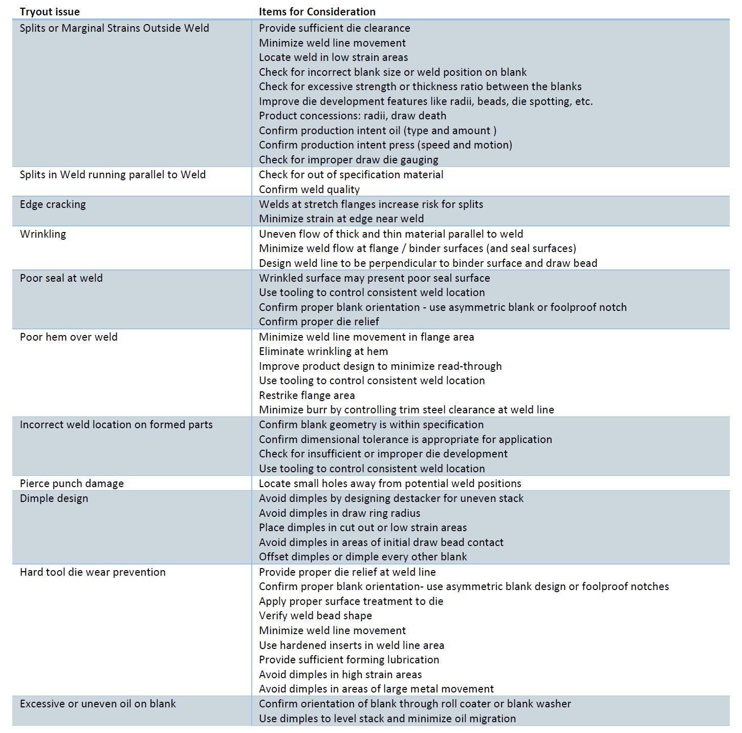
Tailor Welded Blanks Stamping Tryout Issues Checklist.A-20
Case Study: Deploying Tailored Blanks in Electric Vehicles
Many thanks to Isaac Luther, TWB Company, for providing this case study.
Laser-welded blanks (LWBs) allow the combination of different steel grades, thicknesses, and even coating types into a single blank. This results in stamping a single component with the right material in the right place for on-vehicle requirements. This technology allows the consolidation of multiple stampings into a single component.
One example is the front door inner. A two-piece design will have an inner panel and a reinforcement in the hinge area. As shown in Figure 12, a laser welded front door inner incorporates a thicker front section in the hinge area and a thinner rear section for the inner panel, providing on-vehicle mass savings. This eliminates the need for additional components, reducing the tooling investment in the program. This also simplifies the assembly process, eliminating the need to spot weld a reinforcement onto the panel.
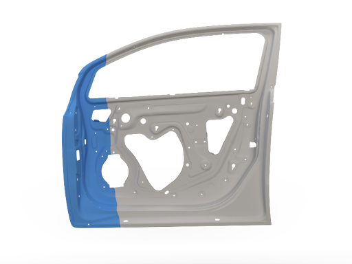
Figure 12: Front Door Inner Stamped from a Laser Welded Blank
Today, large opportunities exist to consolidate components in a BEV in the battery structure. Design strategies vary from different automakers, including how the enclosure is constructed or how the battery mounts into the vehicle. The battery tray can have over 100 stamped components, including sealing surfaces, structural members, and reinforcementsM-68. As an idea, a battery tray perimeter could be eight pieces, four lateral and longitudinal members, and four corners. The upper and lower covers are two additional stamped components, for a total of ten stampings that make up the sealing structure of the battery tray. On a large BEV truck, that results in over 17m of external sealing surfaces.
Part consolidation in the battery structure provides cost savings in material requirements and reduced investment in required tooling. Another benefit of assembly simplification is improved quality. Fewer components mean fewer sealing surfaces, resulting in less rework in the assembly process, where every battery tray is leak-tested.
The deep-drawn battery tub is a consolidated lower battery enclosure and perimeter. This can be seen in Figure 13; a three-piece welded blank incorporates a thicker and highly formable material at the ends and in the center section, either a martensitic steel for intrusion protection or a low-cost mild steel. This one-piece deep-drawn tub reduces the number of stampings and sealing surfaces, resulting in a more optimized and efficient design when considered against a multi-piece assembly. In the previous example of a BEV truck, the deep-drawn battery tub would reduce the external sealing surface distance by 40%. To validate this concept, component level simulations of crash, intrusion, and formability were conducted. As well as a physical prototype built that was used for leak and thermal testing Y-14 with the outcomes proving the validity of this concept, as well as developing preliminary design guidelines. Additional work is underway to increase the depth of the draw while minimizing the draft angle on the tub stamping.
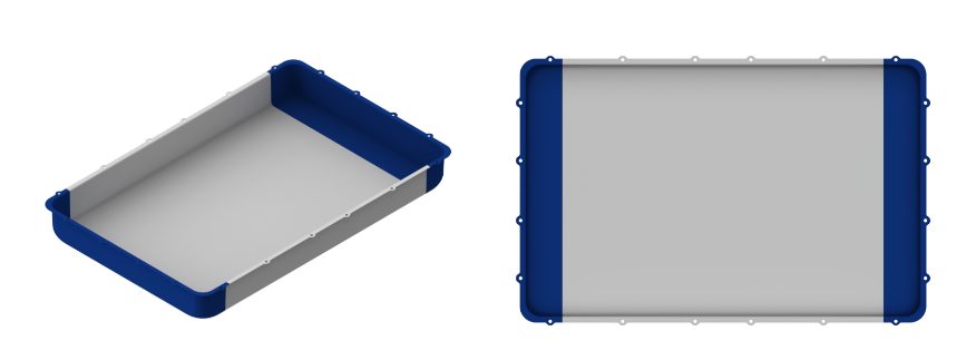
Figure 13: Deep Battery Tub Stamped from a Laser Welded Blank
In most BEVs today, the passenger compartment has a floor structure common in an ICE vehicle. However, the BEV also has a top cover on the battery assembly that, in most cases, is the same size as the passenger compartment floor. In execution of part consolidation, the body floor and battery top cover effectively seal the same opening and can be consolidated into one component. An example is shown below, where seat reinforcements found on the vehicle floor are integrated into the battery top cover, and the traditional floor of the vehicle is removed. Advanced high-strength steels are used in different grades and thicknesses. Figure 14 show what the laser welded battery top cover looks like on the assembly.
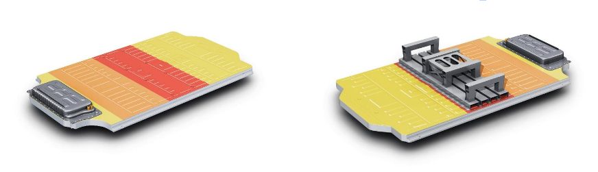
Figure 14: Battery Top Cover from a Laser Welded Blank
Vehicle assembly can also be radically simplified as front seats are mounted on the battery before being installed in the vehicle as shown in Figure 15, the ergonomics of the assembly operation are improved by increased access inside the passenger compartment through the open floor.
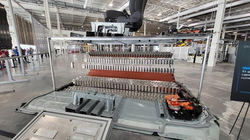
Figure 15: Ergonomics of the Assembly Operation
Cost mitigation is more important than ever before, with reductions in piece cost and investment and assembly costs being important. At the foundation BEVs currently have cost challenges in comparison to their ICE counterparts, however the optimization potential for the architecture remains high, specifically in part consolidation. Unique concepts such as using laser welded blanks for deep-drawn battery tubs and integrated floor/battery top covers are novel approaches to improve challenges faced with existing BEV designs. Laser welded blank applications throughout the body in white and closures remain relevant in BEVs, providing further part consolidation opportunities.

Thanks go to Isaac Luther for his contribution of this case study. Luther is a senior product engineer on the new product development team at TWB Company. TWB Company provides tailor-welded solutions in North America. In this role, Isaac is responsible for application development in vehicle body and frame applications and battery systems. Isaac has a Bachelor of Science in welding engineering from The Ohio State University.
Back to the Top


![Figure 3: General usage of Tailor Welded Coils [S-28]](http://ahssinsights.org/wp-content/uploads/2020/07/tailor-welded-cole-common-use.jpg)


