Blog, homepage-featured-top, main-blog
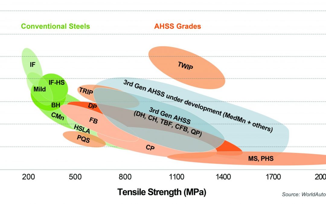
Bubble chart. Banana diagram. Steel strength ductility diagram—it’s been called a lot of things over the years. But the 2021 chart shown in Figure 1 is the subject of hundreds of requests for use we receive from engineers and students all over the world and appears in thousands of presentations and papers. Because of that, we periodically update it to make sure it reflects the most current picture of both commercially available, as well as emerging steel grades. In this blog, we are providing our updated GFD for download as well as definitions of steel classifications, as agreed to by our member companies.

Figure 1: The 2021 Global Formability Diagram comparing strength and elongation of current and emerging steel grades.
Steel Classifications
There are different ways to classify automotive steels. One is a metallurgical designation providing some process information. Common designations include lower-strength steels (interstitial-free and mild steels); conventional high strength steels, such as bake hardenable and high-strength, low-alloy steels (HSLA); and Advanced High-Strength Steels (AHSS) such as dual phase and transformation-induced plasticity steels. Additional higher strength steels include press hardening steels and steels designed for unique applications that have improved edge stretch and stretch bending characteristics.
A second classification method important to part designers is strength of the steel. This document will use the general terms HSLA and AHSS to designate all higher strength steels. The principal difference between conventional HSLA steels and AHSS is their microstructure. Conventional HSLA steels are single-phase ferritic steels with a potential for some pearlite in C-Mn steels.
AHSS are primarily steels with a multiphase microstructure containing one or more phases other than ferrite, pearlite, or cementite – for example martensite, bainite, austenite, and/or retained austenite in quantities sufficient to produce unique mechanical properties. Some types of AHSS have a higher strain hardening capacity resulting in a strength-ductility balance superior to conventional steels. Other types have ultra-high yield and tensile strengths and show a bake hardening behavior.
What are 3rd Gen Steels?
Third Generation, or 3rd Gen, AHSS builds on the previously developed 1st Gen AHSS (DP, TRIP, CP, MS, and PHS) and 2nd Gen AHSS (TWIP), with global commercialization starting around 2020. Third Gen AHSS are multi-phase steels engineered to develop enhanced formability as measured in tensile, sheared edge, and/or bending tests. Typically, these steels rely on retained austenite in a bainite or martensite matrix and potentially some amount of ferrite and/or precipitates, all in specific proportions and distributions, to develop these enhanced properties.
Graphical Presentation
Generally, elongation (a measure of ductility) decreases as strength increases. Plotting elongation on the vertical axis and strength on the horizontal axis leads to a graph starting in the upper left (high elongation, lower strength) and progressing to the lower right (lower elongation, higher strength). When considering conventional steels and the first generation of advanced high strength steels, this shape led to the colloquial description of calling this the banana diagram.
With the continued development of advanced steel options, it is no longer appropriate to describe the plethora of options as being in the shape of a banana. Instead, with new grades filling the upper right portion of Figure 1, perhaps it is more accurate to describe this as the football diagram as the options now start to fall into the shape of an American or Rugby Football. Officially, it is known as the steel Global Formability Diagram.
Even this approach has its limitations. Elongation is only one measure of ductility. Other ductility parameters are increasingly important with AHSS grades, such as hole expansion and bendability. There are several other approaches that have been proposed by experts around the world. Have a look at our Defining Steels article, from which this article was drawn, to learn more about them. You will also find within Defining Steels a detailed explanation of the nomenclature used throughout the Guidelines to define steels. If you have questions, please use the Comments tool below or on the Defining Steels page.
Download the GFD
Because of its popularity, we provide high resolution image files of the GFD here for your download and use. Please source it “Courtesy of WorldAutoSteel” in your papers and presentations. We are happy for you to use it. If you require our signed permission, please write us at steel@worldautosteel.org. We’ll respond quickly.
* The Guidelines use the general terms HSLA and AHSS to designate all higher strength steels.
High Energy Density Welding
This is a summary of a paper by M. Mazar Atabaki, et al, entitled, “Pore formation and its mitigation during hybrid laser/arc welding of advanced high strength steel”M-66, referenced by permission.
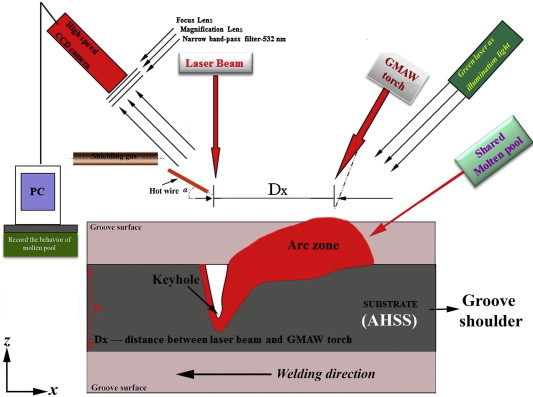
Hybrid laser-arc welding (HLAW) is a popular welding process for thick sections. HLAW combines the high penetration depth and speed of laser welding with the volume and high deposition of gas metal arc welding (Figure 1).
Figure 1: HLAW Diagram.M-66
A common issue with this process is the formation of pores, which researchers from Southern Methodist University in Dallas addressed by optimizing various variables to reduce the presence of pores. HLAW was used to weld two coupons of Advanced High-Strength Steel (AHSS) with a carbon equivalent (CE) of 0.75 wt% (Figure 2). The pores appeared to be caused by two different sources. One type of pore appeared to form when the filling rate of the collapsing keyhole is slower than the solidification rate of the molten material. This left voids (pores) in the material. Other pores were caused by the trapping of shielding gas in the weld pool, a result of the fast solidification rate of laser welding.
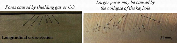
Figure 2: Pores in weldment.M-66
To address the porosity, four variables were focused on:
- Increasing heat input in HLAW; creating a larger weld pool and slower solidification rates, giving more time for gases to escape from the weld pool.
- Optimization of the stand-off distance of the filler wire.
- Application of a side shielding gas.
- Use of a hot wire.
The researchers also found that the presence of certain alloying elements could affect the stability of the keyhole (alloys with a low boiling point). It was also important to find the optimum stand off distance for the wire. When the filler wire was too close, the arc got in the way of the laser and reduced power to the keyhole, causing instability. When a hot wire was used, the fusion zone microstructure consisted of martensite and bainite. Fracture testing showed brittle fracture surface with indications of gas entrapment, emphasizing the need to diffuse gases out of the molten weld pool.
The researchers found that the optimum stand-off distance between the laser and the arc was 8mm. At this distance, the molten weld pool was allowed to widen, which helped with degassing the liquid metal. When combined with a 92%Ar/8%CO side shielding gas, much of the porosity was alleviated. The use of a hot wire also improved the stability of the weld pool reducing some of the longitudinal porosity.
Citations
Citation:
M-66. M. Mazar Atabaki, J. Ma, W. Liu, R. Kovacevic, “Pore formation and its mitigation during hybrid laser/arc welding of advanced high strength steel”, Materials & Design, Volume 67, 2015, Pages 509-521, ISSN 0261-3069, https://doi.org/10.1016/j.matdes.2014.10.072.
Arc Welding
This is a summary of a paper of the same title, authored by K. Májlinger, E. Kalácska, and P. Russo Spena, used by permission.M-65
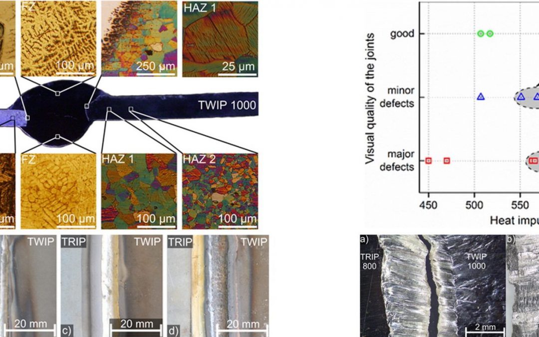
Researchers at the Budapest University of Technology and Economics and the Free University of Bozen-Bolzano tested gas metal arc welding (GMAW) of dissimilar Advanced High-Strength Steel (AHSS) sheets.M-65 The test pieces were 100 x 50 mm samples of 1.4 mm TWIP (TWIP1000) and 0.9 mm TRIP (HCTC800T) sheet steels were welded in a lap joint configuration with 0.8 mm diameter AWS ER307Si austenitic stainless steel wire to determine appropriate GMAW parameters for good quality welds. Quality was determined by external appearance, microstructure, and mechanical properties. Good welds were achieved with linear heat inputs (Q) with ranges from 500-650 kJ/m. The only fractures that occurred appeared within the weld bead by ductile failure modes. The HAZ of the TWIP steel showed grain coarsening and the HAZ of the TRIP steel experienced microstructural changes relative to the distance from the fusion boundary. The ultimate tensile strength (UTS) varies between 73%-84% of the weaker of the two steels.
Welding was conducted with an automated linear drive system with pure Argon (99.996% Ar) shielding gas at 10L/min. Wire feed rates were approximately 3.5 m/min with Direct Current Electrode Positive (DCEP) polarity. Changes in current, voltage, weld speed, and the resulting linear energy are compared in Table 1.
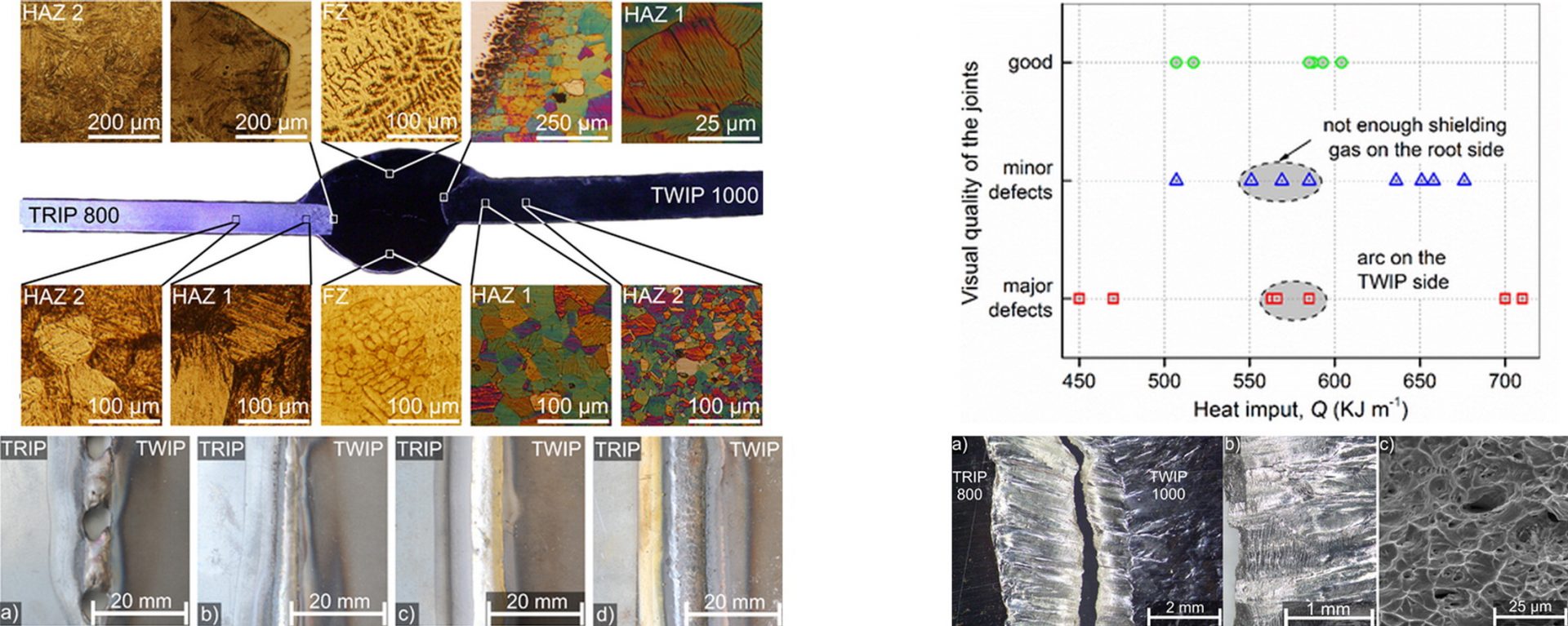
Figure 1: Overview of Dissimilar AHSS GMAW Welding.M-65
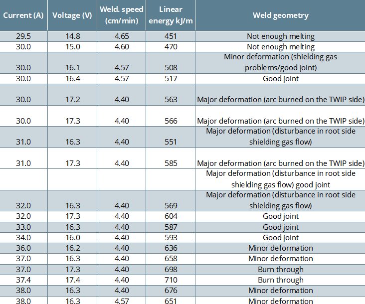
Table 1: Results of the preliminary welding tests in terms of TWIP-TRIP joint quality.M-65
After welding, transverse sections were cut from the welds and etched to show the microstructure. Vickers hardness testing was conducted on the weld samples based on the ASTM E384 standard. Tensile tests were performed on the samples according to the EN ISO 6892-1 standard. Tests were also conducted on unwelded TWIP and TRIP steels for comparison. Scanning electron microscopy (SEM) examinations were made of fracture surfaces to determine failure modes and examine for microscopic weld defects.
The study concluded that dissimilar welds between AHSS steels with the GMAW process can be achieved with consistent results desired for automotive applications.
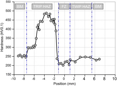
Figure 2: Vickers Hardness Across Weldment.M-65
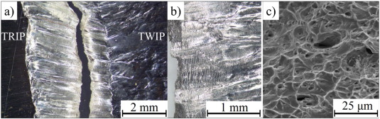
Figure 3: Ductile Failure in the fragile zones (FZ).M-65
Citations
Citation:
M-65. K. Májlinger, E. Kalácska, P. Russo Spena, “Gas metal arc welding of dissimilar AHSS sheets”, Materials & Design, Volume 109, 2016, Pages 615-621, ISSN 0264-1275, https://doi.org/10.1016/j.matdes.2016.07.084