RSW of Dissimilar Steel
This article summarizes a paper entitled, “Higher than Expected Strengths from Dissimilar Configuration Advanced High-Strength Steel Spot Welds”, by E. Biro, et al.B-6
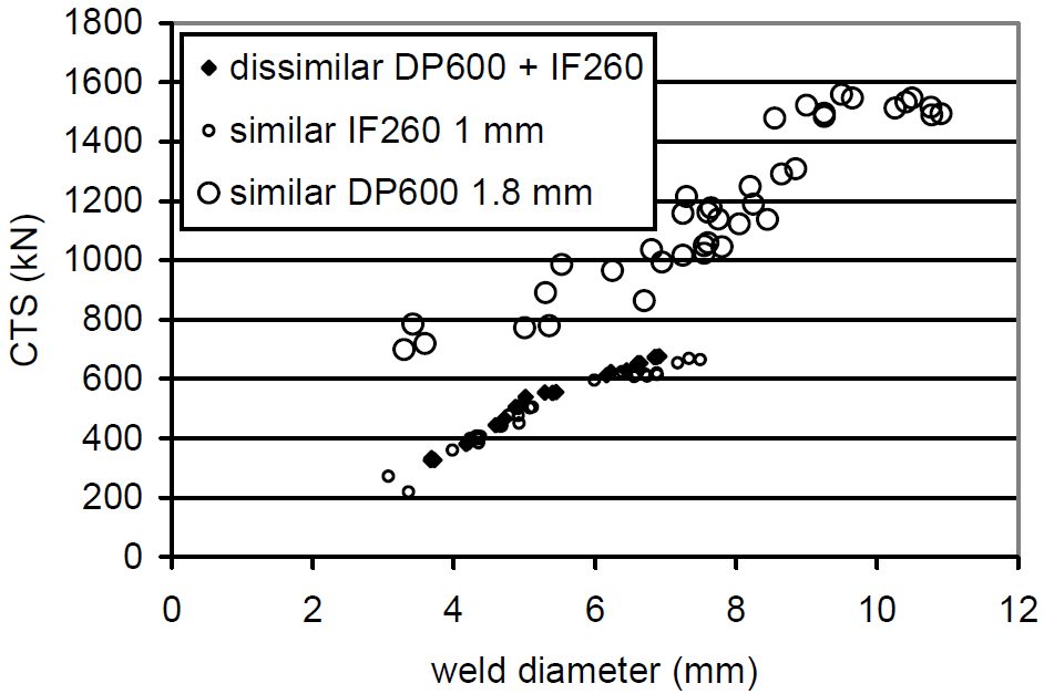
This study shows that the cross tension strength (CTS) is always higher than the strength expected from the lower strength material in the joint. Figure 1 verifies the assumption that the load bearing capacity of a heterogeneous configuration is supposed to equal the minimum strength of both homogenous assemblies. Material used in this study was a 1 mm low carbon equivalent Dual Phase 980 (DP980 LCE) steel.
Figure 1: Example of dissimilar configuration with CTS matching the “minimum rule”.B-6
The materials chosen for this study are in Table 1.
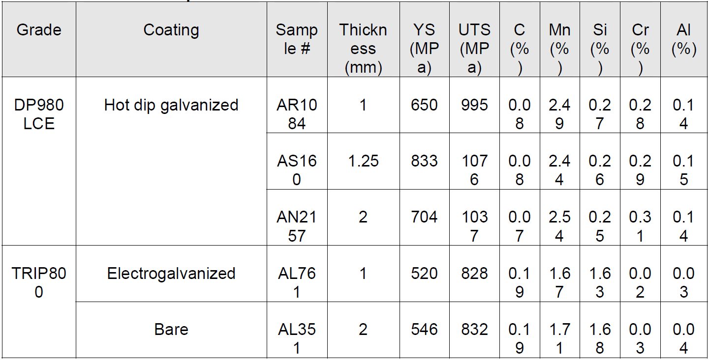
Table 1: Steel sheet samples.B-6
The material thickness combinations for all of the two sheet joints are shown in Table 2.
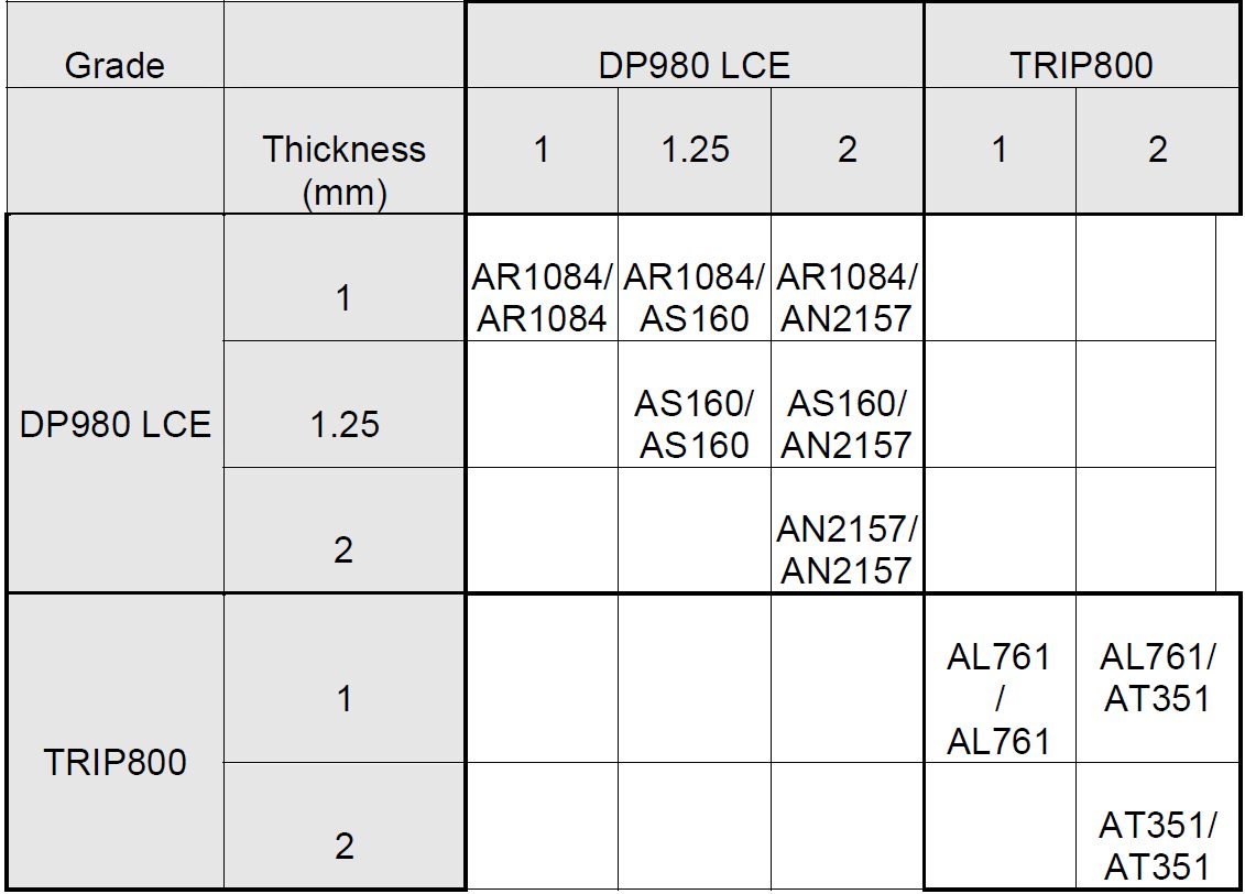
Table 2: Welded 2-sheet configurations.B-6
The three-sheet stackups all were made using the 1 mm DP980 LCE. These configurations were designed to understand what happens in such cases, knowing that three-sheet welding is very common in car body manufacturing. The three-sheet stackup configurations are shown in Figure 2 and are as were follows:
- a square DP980 coupon (patch) is inserted between the two classical cross-tension coupons for welding (1+patch+1 mm);
- two coupons oriented the same way welded with one coupon oriented in the transverse direction to form a cross-tension sample (1+[1+1] mm);
- same configuration as a) but the external coupon is removed by manual torsion before cross-tension testing (1+1+0 mm);
- same configuration as a), but the two coupons oriented the same way are first spot welded together strongly (with several spots) in the extremities, before the actual 3-sheet spot weld is done ([1++++1]+1 mm).
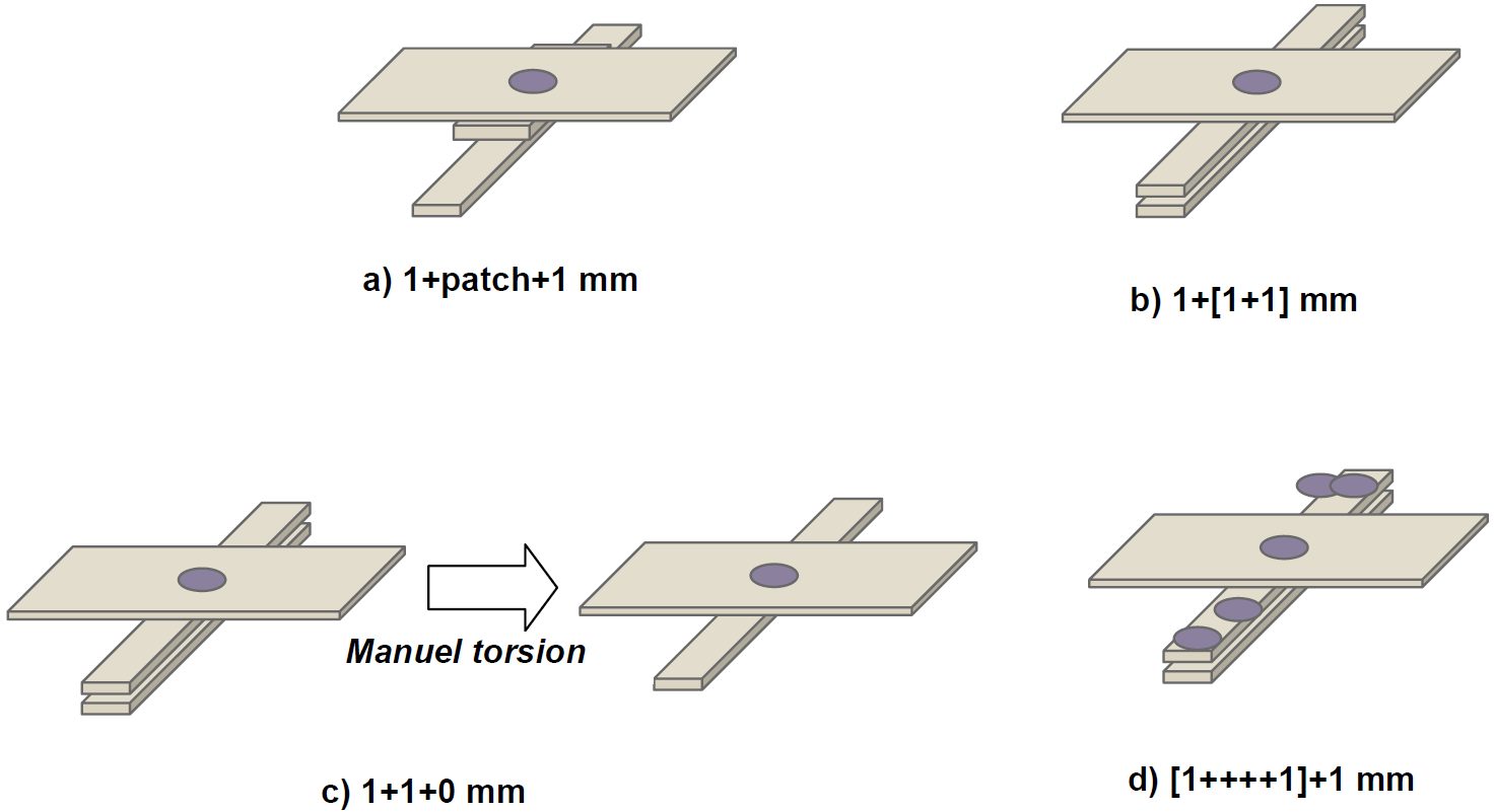
Figure 2: Three-sheet configurations based on 1mm DP980 LCE sample.B-6
The welding parameters for each configuration are listed in Table 3.
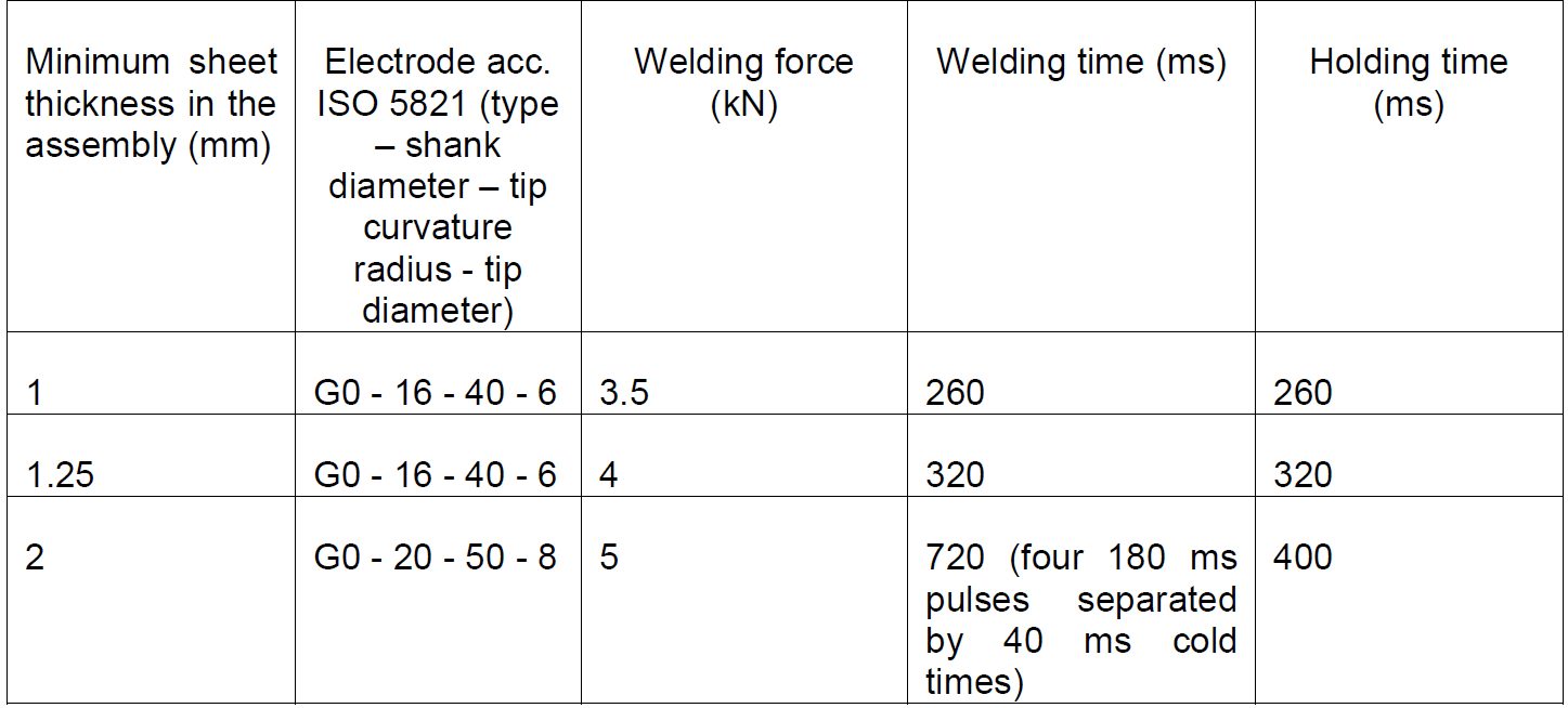
Table 3 : Welding parameters.B-6
CTS is strongly dependent on weld diameter (Figure 3).
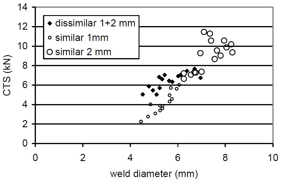
Figure 3: Cross-tension Strength for TRIP800 configurations.B-6
CTS for the main DP980 configurations are shown as a function of weld diameter in Figures 4 and 5.
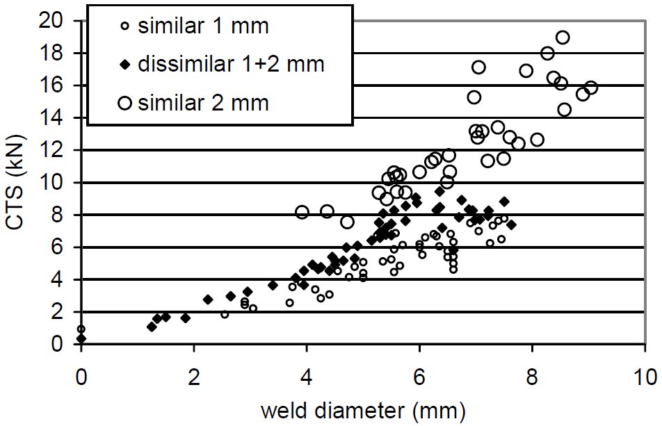
Figure 4: Cross-tension Strength for DP980 1+1, 1+2 and 2+2 configurations.B-6
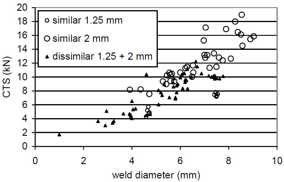
Figure 5: Cross-tension Strength for DP980 1.25+1.25, 1.25+2 and 2+2 configurations.B-6
The three-sheet configurations based on 1mm DP980 LC results are shown in Figures 6 and 7. These results again verify that dissimilar configuration performances appear above the “minimum rule” assumption described in Figure 1.
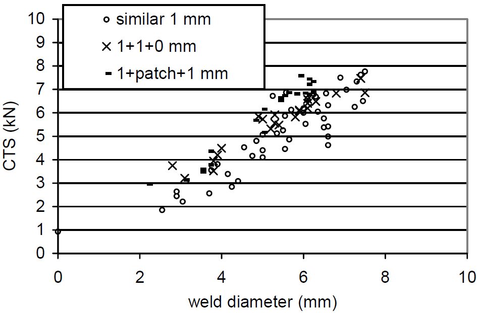
Figure 6: Cross-tension Strength for DP980 1+1, 1+1+0 and 1+patch+1 configurations.B-6
![Figure 7: Cross-tension Strength for DP980 1+1, 1+2, 1+[1+1]and [1+++1]+1 configurations.](https://ahssinsights.org/wp-content/uploads/2020/07/3114c_Fig7.jpg)
Figure 7: Cross-tension Strength for DP980 1+1, 1+2, 1+[1+1]and [1+++1]+1 configurations.B-6
The observation that CTS is greater than predicted by the “minimum rule” has been called a “positive deviation” from the expected strengths.
This work concluded that while material qualification tests are frequently based on similar welding configurations, real car body applications are quite systematically dissimilar configurations. For spot welds failing in plug mode, the strength of the assembly only depends on the weakest material strength. In case of AHSS+AHSS welded combinations, however, things turn out to be different. Similar grade but dissimilar thickness High-Strength Steel configurations have been spot welded and tested in Cross-Tension. The following main conclusions can be highlighted:
- For dissimilar thickness configurations, the cross-tensile strength is above the standard “minimum rule” assumptions, this phenomenon being called a “positive deviation”;
- Limited thermal and notch location effects can explain part of this positive deviation, but the main reason is mechanical;
- As evidenced through several analytic and numerical studies, this mechanical effect is due to the less severe local stresses at the notch in case of uneven thickness, and improves the positive deviation when the thickness ratio increases. Although widely used for material qualification and scientific purposes, similar configurations appear as the worst case in terms of cross-tension performance for high strength steels. Actual vehicle design should consider positive deviation in dissimilar configurations to maximize the potential strength of spot welds in High-Strength steels.
Manufacturing Issues
Spot Welding of Three Steel Sheets with Large Thickness Ratios
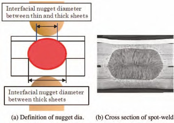
Car parts such as side panels are fabricated by spot welding three steel sheets together. When the outer steel sheet is a thin sheet of mild steel and the reinforcement steel sheets are thick sheets of HSS (that is, when there is a large thickness ratio between the sheets), it is often difficult to spot weld such sheets together. The term “thickness ratio” as used herein refers to the total thickness of the three steel sheets divided by the thickness of the thinnest steel sheet. Nuggets obtained by spot welding of three steel sheets are illustrated in Figure 1 (a). In the spot welding of three steel sheets with a large thickness ratio, it is difficult to form a nugget at the interface between thin and thick steel sheets, as shown in Figure 1 (b). The reason for this is that in spot welding, because of heat removal by the water-cooled electrode, the fusion progresses from the thickness center of the three steel sheets toward the outside, except for the heat generated by contact resistance at the steel sheet surfaces in the early stages of welding time. In addition, in view of the dimensional accuracy of actual members, it is necessary to set appropriate welding conditions when there is a gap between steel sheets. In practice, the proper welding current range is as shown in Figure 2. However, the welding current range is often narrower in one-step spot welding.
Figure 1: Three sheets spot welded.N-5
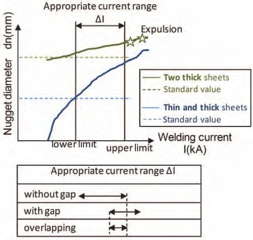
Figure 2: Weldability lobe of three sheets spot welded.
As a means of solving the above problem when there is no gap between the steel sheets, a method has been proposed in which the diameter of the electrode tip at the thin-sheet side is reduced and the welding force and current are varied during the welding time. In addition, a two- step pulsating current welding method (Figure 3) has been proposed in which neither the electrode diameter nor the welding force are changed. This method is described briefly below. Initially, during the first welding step, a relatively large welding current is passed to generate heat by using the contact resistance at the interface between the thin and thick steel sheets and that between the thick steel sheets. This method does not positively use the contact resistance that is effective when the electrode force is low. Since the method can be applied even under a high electrode force, it is particularly effective when there is a gap between the steel sheets to be welded together.
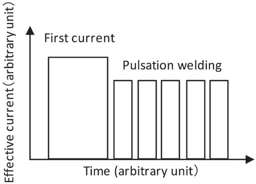
Figure 3: Welding current pattern.
An experiment was conducted by using the above technology. The materials used were a 0.6- mm-thick sheet of mild steel and two 1.6-mm-thick sheets of HSS (980 MPa class). Spacers 1.4-mm thick were inserted at intervals of 40 mm between the thin and thick steel sheets and between the thick steel sheets. A servomotor-driven, single-phase AC welder was used for the test. The electrode used was a Cr-Cu dome radius type with a 40-mm tip upper radius and 6-mm tip lower diameter. The welding force was 3.43 kN. To evaluate the diameter of fusion at the interface between the thin and thick sheets, which determines the proper current range, a chisel test was conducted at the interface and evaluated the plug diameter.
The test results are illustrated in Figure 4. The horizontal axis represents the first step welding current for one-step welding (welding time t1 = 18 cycles) and the second-step welding current for two-step welding (first welding time t1 = 18 cycles, second welding time t2 = 8 cycles) or pulsation welding [t1 = 18 cycles, t2 = (5-cycle heat/2-cycle cool) × 5]. For one- or two-step welding, the welding current range was less than 1 kA. Conversely, with pulsation, it was possible to secure a proper welding range of 3 kA or more (about 1.8 kA when there was no gap between the steel sheets).
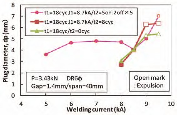
Figure 4: Current ranges for different welding current patterns.
In addition to the two-step pulsating current welding method (Figure 4 above), preheating the sheets at 20-25% of the normal current before beginning the impulses can be effective when joining three layers of extremely different thicknesses. Figure 5 shows a weld cross section using preheating prior to three impulses.
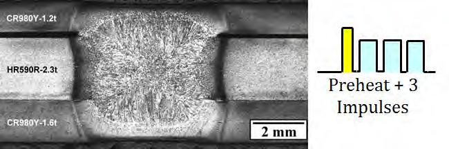
Figure 5: Cross section of three sheet spot weld including preheating prior to pulsations.C-6
Another solution to RSW three sheets is when the Fusion Zone (FZ) formation process is controlled by setting the welding current and welding force during welding in multiple steps; this is referred to as Intelligent Spot Welding. (ISW). Using this approach, nugget formation between a thin sheet and thick sheet becomes possible when reduced welding force is applied. In Step 1 of the welding process, a FZ is reliably formed between the thin sheet and thick sheet by applying conditions of low welding force, short welding time, and high current. In the subsequent Step 2, a FZ is formed between the two thick sheets by apply high welding force and a long welding time. The results are shown in Figure 6, in which welding is performed with the edge of three steel sheets positioned directly under the electrodes, and the behavior of FZ formation at the edge of the sheets was observed with a high-speed video camera. Condition (a) is welding under a constant welding force and condition (b) is ISW. In condition (a), a nugget was formed between the two thick sheets, but the nugget failed to grow to the thin sheet-thick sheet joint, and the two sheets were not welded. However, condition (b) shows that nuggets have formed between both the thin and thick sheet and between the two thick sheets. The optimal welding current range for Step 2 can be determined from nugget formation between the two thick sheets, resulting in a wide available current range equal to or greater than that in joint welding of two thick sheets.
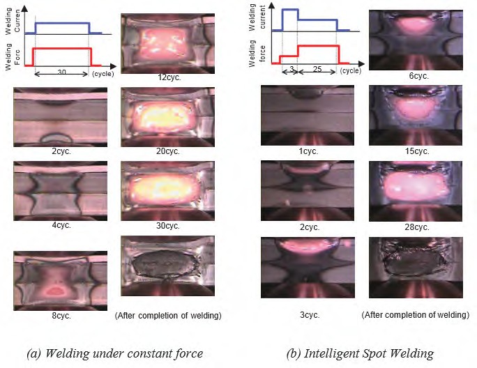
Figure 6: Results of observation of FZ formation phenomenon in RSW of three-sheet joint by high-speed video camera.J-1
Application of Spot Welding to Hollow Members
In spot welding of car bodies, the so-called direct spot welding (in which the welding current is passed while two or more steel sheets are pressed against each other) by the welding electrodes is used most commonly. However, for those parts with closed cross sections, it may become necessary to drill a working hole through which the electrodes for direct spot welding of the steel sheets can be passed. In this case, the decline in rigidity of the drilled part being compensated for by using a thicker steel sheet or providing a reinforcing member will inevitably increase the weight of the car body. Therefore, attempts were made to reduce the steel sheet thickness (weight) and secure the required stiffness simultaneously without drilling any hole in the steel sheets. Indirect spot welding was used, in which the steel sheets are pressed and welded by a couple of electrodes from one side at the same time. Because the steel sheets are pressed by electrodes from one side, the weld sinks and the area of contact between the steel sheets increases (the current density decreases) if an excessive force is applied, making it difficult to perform fusion welding. Conversely, if an excessively large current is applied, the local current density between the electrodes increases because of a shunt current, causing a crack or explosion.
Studies were made for various welding conditions for the combination of a hollow member with a 1.6-mm wall thickness and a sheet-formed member with a 0.7-mm thickness. By using an electrode with a specially designed tip and a DC power supply in combination, indirect spot welding could be performed of the above members without requiring any special pattern of conduction or pressing, even in the presence of a gap between the members or the presence of shunts (existing welding points). An example of the cross section of an indirect spot weld is illustrated in Figure 1, which clearly indicates that a sufficiently large nugget was formed.
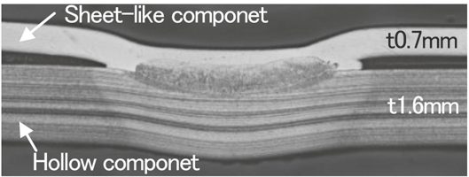
Figure 1: Cross section of indirect spot weld for hollow and sheet-like components.
For the indirect RSW with single-side access of the welding electrode, the variable controls of electrode force and current during welding were developed to promote the weld nugget formation. Experiments as well as numerical simulations were conducted to study the welding phenomena and optimize the welding process. It was verified that the nugget was stably formed with the developed process even when shunting was large. Figure 2 describes the effect of variable current and force on the promotion of weld nugget formation.
At the first stage with low welding current and high electrode force, the electric conduction with sufficient load at weld preheats the sheet, which promotes contacting area between the electrode and upper sheet and thus inhibits the expulsion from the surface. Meanwhile, contacting area between upper and lower sheets is also promoted forming the stable conduction path. Subsequently, at the second stage with high welding current and low electrode force, the nugget formation is effectively promoted with a heated region concentrated at the center in weld, avoiding the further penetration of welding electrode into the upper sheet and thus maintaining the current density.
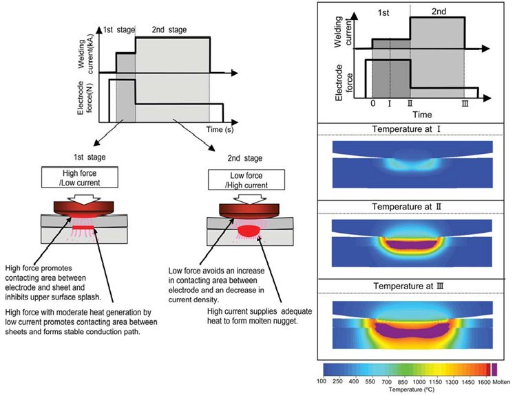
Figure 2: Concept of nugget formation process of variable current and force control for single-sided RSW.J-1
Back To Top