Resistance Spot Welding: 3T and 4T Dissimilar Steel Stack-ups for Automotive Applications

Resistance Spot Welding: 3T and 4T Dissimilar Steel Stack-ups for Automotive Applications

Car body-in-white (BIW) structures, such as pillars and rails, are increasingly made of complex stack-ups of advanced high-strength steels (AHSS) for vehicle lightweighting to achieve improved fuel efficiency and crashworthiness. Complex stack-ups comprise more than two sheets with similar/dissimilar steels and non-equal sheet thicknesses. 

Resistance spot welding (RSW) of complex stack-ups can be challenging, especially when a thin sheet of low-strength steel is attached to multiple thick AHSS sheets with a thickness ratio of five or higher (thickness ratio = total thickness of the stack-up/thickness of the thinnest sheet). In such a case, the heat loss is much faster on the thin sheet side than on the thick sheet side, and consequently, obtaining sufficient penetration into the thin sheet without expulsion on the thick sheet side can be challenging.

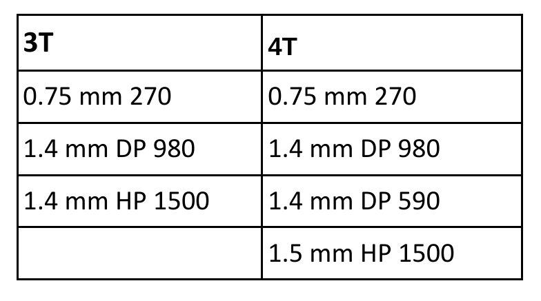
An example of two automotive applications involving complex AHSS steel stack-ups is shown below.


automotive applications involving complex AHSS steel stack-ups

Examples of automotive applications involving complex AHSS steel stack-ups


For welding 2T steel stack-ups, the weld schedule may be relatively simple and utilize just one current pulse with a specific weld time. However, typical RSW machines and controllers can customize and precisely control each parameter indicated in Figure 1.  

Spot Welding Schedule/Cycle

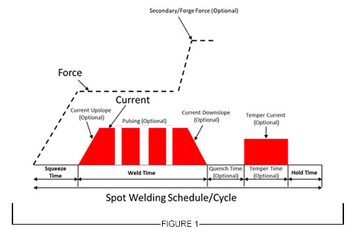
Figure 1: General Description of Resistance Spot Welding Schedule


For RSW 3T and 4T applications, more advanced schedules are needed to achieve good weld nugget penetration through all the interfaces in the stack-up. To achieve this objective,  the use of multiple current pulses with short cool time in between the pulses showed to be most effective, and in some cases, the application of a secondary force showed to be beneficial.

Figure 2 describes a method for joining the 3T stack-up using two current pulses. The first one is a short-time pulse that does not allow enough time for the electrode cooling to dominate at the top sheet, so a weld can easily form between the top and middle sheet. Once that nugget has formed, the second pulse utilizes a lower current and longer time to form the second nugget, which then grows into the first nugget to form a single weld. 

This approach can be also used with electrode force variation during the welding cycle to provide additional control of the contact resistances, but of course, it is limited to machines that are capable of varying force during the weld cycle.

Typical pulse times are 50 – 350 ms with cool times of 20 – 35 ms and current levels between 8 – 15 KA, depending on materials type and thickness. 


RSW Schedule for Joining 3T Stack-Up Using 2 Current Pulses

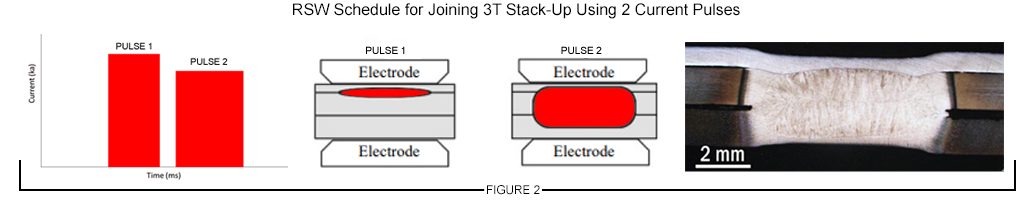
Figure 2: Example of RSW Schedule for Joining 3T Stack-Up Using 2 Current Pulses


A 4T stack-up example is shown in Figure 3. In this case, a similar approach was used with three current pulses applied during the weld cycle to produce a weld through all interfaces. 

The common theme in resistance spot welding all complex stack-ups is using a complex, multi-pulse weld cycle. These more complex schedules should be developed experimentally and potentially with computational modeling. Another consideration that may be beneficial in some cases is to vary the top and bottom electrode face diameter, such as that the smaller electrode face is on the thinner material side of the stack-up.


RSW Schedule for Joining 4T Stack-Up Using 3 Current Pulses

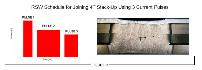
Figure 3: Example of an RSW Schedule for Joining 4T Stack-Up Using 3 Current Pulses


Thanks is given to Menachem Kimchi, Associate Professor-Practice, Dept of Materials Science, Ohio State University and Technical Editor – Joining, AHSS Application Guidelines, for this article.

Mechanical Joining

Mechanical Joining

Examples of mechanical joining in automotive manufacturing are clinching and self-piercing riveting. The process steps and typical equipment for both processes are shown in Figure 1.  A simple round punch presses the materials to be joined into the die cavity. As the force continues to increase, the punch side material is forced to spread outward within the die side material.

Figure 1: Process steps and equipment for mechanical joining in automotive industries.

Figure 1: Process steps and equipment for mechanical joining in automotive industries.


This creates an aesthetically round button, which joins cleanly without any burrs or sharp edges that can corrode. Even with galvanized or aluminized sheet metals, the anti-corrosive properties remain intact as the protective layer flows with the material. Table 1 shows characteristics of different mechanical joining methods.

Table 1: Characteristics of mechanical joining systems.T-12

Table 1: Characteristics of mechanical joining systems.T-12


In a recent study conducted to assess the feasibility of clinch joining advanced HSST-8, it was concluded that 780-MPa DP and TRIP [link to steel material grades] steels can be joined to themselves and to low-carbon steel (see Figure 2). However, 980 DP steel showed tears when placed on the die side (Figure 3). These cracks were found at the ferrite- martensite boundaries (Figure 4). However, these tears did not appear to affect the joint strength. More work is needed to improve the local formability of 980 MPa tensile strength DP steel for successful clinch joining.

Figure 2: Cross sections of successful clinch joints in 780-MPa tensile.

Figure 2: Cross sections of successful clinch joints in 780-MPa tensile.


Figure 3: Clinch joint from DP 980-MPa steel showing tears on the die side.

Figure 3: Clinch joint from DP 980-MPa steel showing tears on the die side.


Figure 4: SEM views of tears found in 980-MPa tensile strength DP steel clinch joints.

Figure 4: SEM views of tears found in DP 980-MPa steel clinch joints.


Circular clinching without cutting and self-piercing riveting (existing half-hollow-rivets) are not recommended for materials with less than 40% hole expansion ratio (λ) as shown in Figure 5. Clinching with partial cutting may be applied instead.

Figure 5: Balance between elongation and stretch flangeability of 980-MPa tensile-strength class AHSS and surface appearance of mechanical joint at the back side.N-1

Figure 5: Balance between elongation and stretch flangeability of 980-MPa tensile-strength class AHSS and surface appearance of mechanical joint at the back side.N-1


Figure 4.P-6: Example of DP 300/500 with a self-piercing rivet.G-2

Figure 6: Example of DP 300/500 with a self-piercing rivet.G-2


Warm clinching and riveting are under investigation for material with less than 12T total elongation. As with any steel, equipment size and clinch/pierce force are proportional to the material strength and tool life is inversely proportional to material strength.

The strength of self-piercing riveted AHSS is higher than for mild steels. Figure 4.P-6 shows an example of a self-piercing rivet joining two sheets of 1.5-mm-thick DP 300/500. AHSS with tensile strengths greater than 900 MPa cannot be self-piercing riveted by conventional methods today.

Self-piercing rivet joints are typically similar or slightly weaker in strength when compared to spot welds. It is largely dependent on the punch-die size, design, and rivet size. However, self-piercing rivets usually perform better in fatigue loading compared to spot welds because there is no notch effect such as what exists in spot-welded joints Figure 7 (left)]. Although clinch joining is being used in several automotive applications, their performance is lower as shown in Figure 7 (right). Thus, they are not recommended for critical joints in automotive manufacturing.

Figure 7: Strength performance for various mechanical joining methods

Figure 7: Strength performance for various mechanical joining methods.


Hybrid Riveting Adhesive

Self-piercing rivets can also be combined with adhesives to result in increased initial stiffness, YS, failure loads and fatigue strength when compared to spot welds using adhesives (Figure 8).

Figure 8: Tensile shear strength of SPR with adhesives and RSW with adhesives.

Figure 8: Tensile shear strength of SPR with adhesives and RSW with adhesives.