homepage-featured-top, main-blog, News
There is interest in the sheet metal industry on how to adopt Industry 4.0 into their legacy forming practices to significantly improve productivity and product quality. Figure 1 illustrates four important variables influencing part quality: material properties, die friction response, elastic deflection of the tool, and press dynamic characteristics. These variables are usually difficult to measure or track during the production runs. When these variables significantly influence the part quality and the scrap rate increases, the operators manually adjust the forming press parameters (speed and pressure), lubricant amount, and tooling setup. However, these manual adjustments are not always possible or effective and can be costly for the increased part complexity.

Figure 1: Important variables influencing the stamping quality.H-35
The ultimate vision for Industry 4.0 in sheet metal forming is an autonomous forming process with maximum process efficiency and minimum scrap rate. This is very similar to the full self-driving (FSD) vision of the electric vehicle today. This will be valuable for the automotive industry that has to process large production volumes with various steel grades.
For example, normal variations of the incoming material properties for Advanced High-Strength Steel (AHSS) may have a significant effect on part quality associated with necking, wrinkling, and cracking, which in turn drastically increases the production cost. This variation of the incoming material properties increases uncertainty in sheet metal forming by making consistent quality more challenging to achieve, thereby increasing the overall manufacturing cost. A nondestructive evaluation (NDE) can be a useful tool to measure incoming material properties.
There are several types of NDE sensors. Most of the sensors need further development or are not suitable for production applications. However, some of the NDE sensors, such as the eddy current tools, laser triangulation sensors equipment, and equipment developed by Fraunhofer IZFP called 3MA (micromagnetic, multiparametric microstructure, and stress analysis), have already been applied to a few limited production applications. These sensors can be used to provide data during production to select the optimal parameters. They also can be used to obtain material properties for finite element model (FEM) analysis. Studies in deep drawing of a kitchen sink production used a laser triangulation sensor to measure the sheet thickness and an eddy-current sensor to measure the yield strength, tensile strength, uniform elongation, elongation to break, and grain size of the incoming material. The material data is used as an input for simulations to generate the metamodels to determine the process window, and it is used as an input for the feed-forward control during the process.K-27
Figure 2 shows how NDE tools are used for feed-forward controls and cameras for feedback control to determine the optimum press setting on sink forming production.

Figure 2: Process control for sheet metal forming of kitchen sink production.H-36
Another study proposed the use of Fraunhofer’s 3MA equipment to determine the mechanical properties of incoming blanks for a sheet forming process. The 3MA sensor correlates the magnetic properties of the material with the mechanical properties and calibrates the system with the procedure outlined in Figure 3. The study showed a good correlation between the measurements from the sensor and the tensile testing results; however, the sensor should be calibrated for each material. Also, the study proposed to use a machine-learning algorithm instead of a feed-forward control to predict the most effective parameters during the drawing process.K-28

Figure 3: Calibration procedure for 3MA sensors.K-28
Technologies associated with Industry 4.0 have a natural fit with AHSS. The advanced slide motion capabilities of servo presses combined with active binder force control can be paired with stamping tonnage and edge location measurements from every hit to create closed-loop feedback control. With press hardening steels (PHS), vision sensors and thermal cameras can be used for controlling the press machine and transfer system.
Have a look at the Dr. Kim’s detailed article on Industry 4.0 for more examples of NDE sensors, as well as information on applying Industry 4.0 to forming process controls.
Industry 4.0 and AHSS Applications
The manufacturing industry is currently experiencing a significant transformation of digitalization, connectivity, and higher flexibility of the manufacturing process. Recently, several studies were conducted by different researchers and companies on developing more complicated control systems with new sensors and applying a machine-learning algorithm to analyze the collected data from the sensors. Therefore, an extensive literature review was conducted to address the applications of Industry 4.0 (sensor, process control, and forming equipment control) for sheet metal forming.
This article introduces the latest information and provides insight on how to practically implement newly introduced technologies and tools for industrial sheet metal forming processes to make the forming processes more efficient and robust.
Needs for Industry 4.0 in Manufacturing
Manufacturing processes have become more efficient and productive with help from smart machines, intelligent systems, and data analytics. This rapid change in manufacturing leads to a new industrial revolution, frequently called Industry 4.0.
Industry 4.0 has been defined as “a name for the current trend of automation and data exchange in manufacturing technologies. It includes cyber-physical systems, the Internet of things (IoT) and cloud computing and cognitive computing and creating the smart factory”.I-17
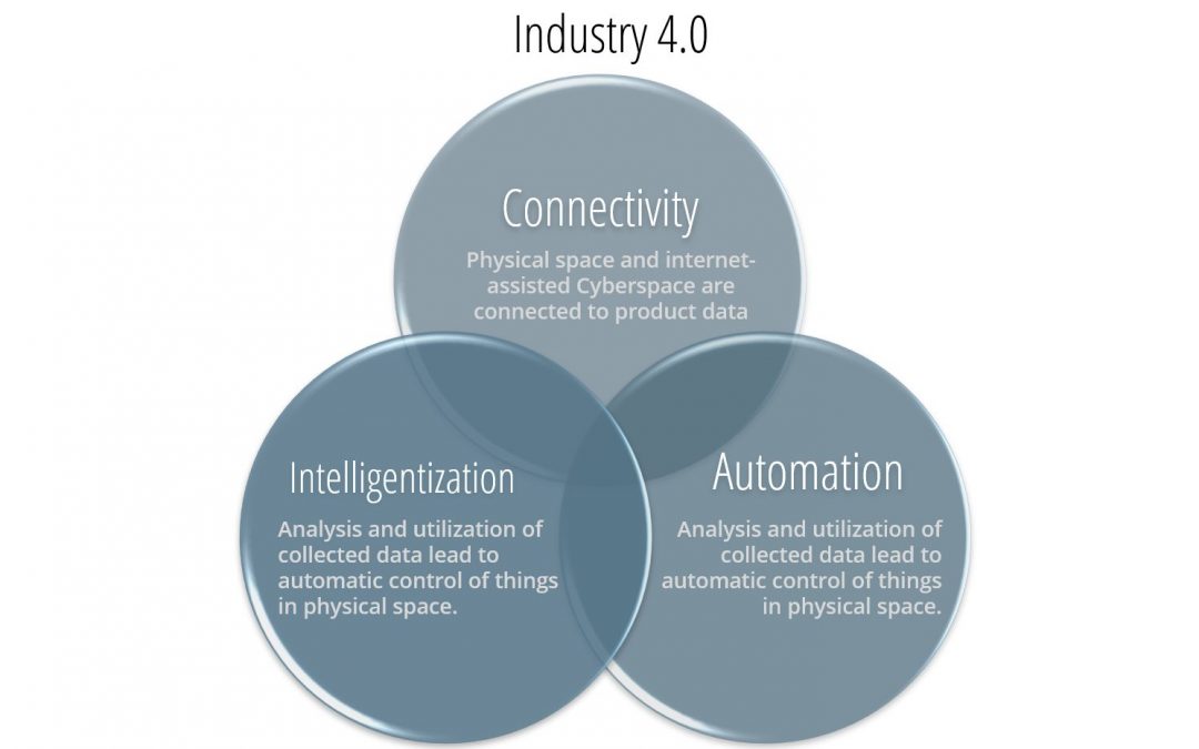
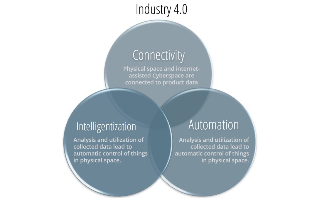
Three key factors — connectivity, intelligentization, and automation (Figure 1) — characterize this new industrial revolution. The combination of these factors changes conventional production to a more customized, flexible, and on-demand manufacturing production, creating significant technical challenges.Y-13 To overcome these challenges, the integration of the three key factors highlighted in Figure 1 becomes essential for the manufacturing industry.

Figure 1: Key factors for Industry 4.0.Y-13
There is interest in the sheet metal industry on how to adopt Industry 4.0 into their legacy forming practices to significantly improve productivity and product quality. Figure 2 illustrates four important variables influencing the part quality: material properties, die friction response, elastic deflection of the tool, and press dynamic characteristics. These variables are usually difficult to measure or track during the production runs. When these variables significantly influence the part quality and the scrap rate increases, the operators manually adjust the forming press parameters (speed and pressure), lubricant amount, and tooling setup. However, these manual adjustments are not always possible or effective and can be costly for the increased part complexity. The use of new advanced high-strength and light-weight materials often escalates technical challenges associated with formability and robustness of the current forming process as well.
Figure 2: Important variables influencing the stamping quality.H-35
The ultimate vision for Industry 4.0 in sheet metal forming is an autonomous forming process with maximum process efficiency and minimum scrap rate. This is very similar to the full self-driving (FSD) vision of the electric vehicle today.
The workflow of the current forming process starts by supplying the incoming coil or blank to the forming press where the material is formed and ends with the inspector assessing the part quality manually (Figure 2).K-27 Implementing Industry 4.0 technology will significantly change the workflow of the future forming process as illustrated in Figure 3. More sensors will be used to measure and monitor the variations of the incoming material, gauge, lubricant, temperature, and part quality. The digital data from the sensors will be analyzed using the data analytic method such as ‘machine learning’ and ‘deep learning.’ The analyzed data will be used to create a digital twin model or an algorithm for intelligently controlling the machines such as the part transfer system, forming press, and quality inspection robots. Likewise, the electronic vehicle progressively evolves in different levels of the FSD. In the early development stage, the prediction results of the artificial intelligence (AI) model will be checked and implemented by the machine operators for controlling the machine. When the AI model is sufficiently trained with the enormous production data, the autonomous forming process will be developed. This will be valuable for the automotive industry that has to process large production volumes with various steel grades. For example, the automotive industry increasingly experiences variations of the incoming material properties for Advanced High-Strength Steel (AHSS) and the significant effect on part quality associated with necking, wrinkling, and cracking, which drastically increases the production cost.

Figure 3: Comparison of the workflow of the current and future forming process with Industry 4.0.K-27
State-of-Art Sensors, Process Control, and Machine Control
Sensors for sheet metal forming: In-line monitoring of the incoming material properties using NDE sensors
The variation of the incoming material properties increases uncertainty in sheet metal forming by decreasing the consistent quality and increasing the overall manufacturing cost. A nondestructive evaluation (NDE) can be a useful tool to measure incoming material properties.
There are several types of NDE sensors. Most of the sensors need further development or are not suitable for production applications. However, some of the NDE sensors, such as the eddy current tools, laser triangulation sensors equipment, and equipment developed by Fraunhofer called 3MA (micromagnetic, multiparametric microstructure, and stress analysis), have already been applied to a few limited production applications. These sensors can be used to provide data during production to select the optimal parameters. They also can be used to obtain material properties for finite element model (FEM) analysis. Studies in deep drawing of a kitchen sink production used a laser triangulation sensor to measure the sheet thickness and an eddy-current sensor to measure the yield strength, tensile strength, uniform elongation, elongation to break, and grain size of the incoming material. The material data is used as an input for simulations to generate the metamodels to determine the process window, and it is used as an input for the feed-forward control during the process.K-27 Figure 4 shows how NDE tools are used for feed-forward controls and cameras for feedback control to determine the optimum press setting on sink forming production.
Figure 4: Process control for sheet metal forming of kitchen sink production.H-36
Another study proposed the use of Fraunhofer’s 3MA equipment to determine the mechanical properties of incoming blanks for a sheet forming process. The 3MA sensor correlates the magnetic properties of the material with the mechanical properties and calibrates the system with the procedure outlined in Figure 5. The study showed a good correlation between the measurements from the sensor and the tensile testing results; however, the sensor should be calibrated for each material. Also, the study proposed to use a machine-learning algorithm instead of a feed-forward control to predict the most effective parameters during the drawing process.K-28
Figure 5: Calibration procedure for 3MA sensors.K-28
Sensors for sheet metal forming: Real-time monitoring of part quality
Many researchers studied the control of the material flow by measuring the draw-in since the strain field of the blank is directly related to the failure. However, it is difficult to measure draw-in over the entire blank during the process so few locations on the blank can be measured. Figure 6 shows various sensors to monitor and control the material draw-in during forming. An extensive list of sensors applicable to metal forming was introduced.P-23

Figure 6: Sensors to monitor (left) and actuators to control (right) material flow and drawn-in for sheet metal forming.A-57
Sensors for real-time monitoring of part quality: Linear variable differential transducer (LVDT)
A LVDT was used to measure the material draw-in (sensor j in Figure 6 – double clicking the image will open it in a new window for ease of reference). However, it has several limitations. First, additional effort is needed for initial setup and maintenance in service which is difficult to apply for stamping productions that are exposed to tool vibration and tool temperature change. Secondly, they are not reliable if splitting or cracking occurs in the process. Finally, when the edge of the blank starts to wrinkle, the sensor could lose the edge and the measurement will be incorrect.L-33, M-29
Sensors for real-time monitoring of part quality: Roller-ball sensor
The roller-ball sensor (sensor b in Figure 6) is a computer mouse-type draw-in sensor based on a rotatory contact between the blank and the sensor. This sensor can measure the direction of the material flow; however, the contacting ball and roller might have wear issues, which can lead to incorrect measurements and high risk of any dirt contaminating the roller-ball contact surfaces. The roller-ball sensors are integrated into the tool, which increases the maintenance and development cost.L-33, M-29
Sensors for real-time monitoring of part quality: Inductance-based transducer
An inductance-based transducer sensor was developed to measure the draw-in during the forming process (Figure 7).M-29 This non-contact sensor has a thick cover of epoxy, protecting it from wear. It is also relatively easy to use and has a low cost. However, it must be calibrated for each material and the measurement error can increase considerably if wrinkling occurs during the forming process. Same as the roller-ball sensor, the inductance-based transducer is integrated into the tool, which increases the maintenance and development cost.

Figure 7: Principle of the inductance-based transducer sensor.M-29
Sensors for real-time monitoring of part quality: Vision sensor
A non-contact in-line sensor was developed to measure the material flow of a deep drawing process.D-25 This sensor has no risk of wear because it is non-contact. This sensor also detects the material flow direction. However, the sensor is integrated into the tool, thus there is a risk of degrading the performance of the sensor due to contamination on the lens with dirt and oil.
Cameras have been used to measure the draw-in between a 2-step drawing process of sink production.F-22 Cameras have a great advantage to measure material draw-in compared with other sensors because they are not integrated into the tool. For example, cameras can be used in different dies to measure the draw-in of the edge of the blank as shown in Figure 8. However, the draw-in cannot be measured continuously while the die is closed. It can only be measured after the die is opened and before the part is transferred to the next station. This is still an in-line control because it allows the adjustment of the planned schedule during the production. Nevertheless, for a single drawing stage process, it is an off-line close-loop control since it only allows adjustment between parts.

Figure 8: Image of the draw-in measurement taken with a camera.F-22
Similarly, a machine vision system with four cameras was used for real-time monitoring of the stamping part quality immediately after the die opened as shown in Figure 9.K-29 The system is capable of not only capturing the part quality with multiple images but also measuring the flange draw-in length of the part.

Figure 9: Real-time monitoring of the stamping quality using camera system.K-29
Recent advancements in optical measurement techniques, including high-resolution imaging and laser displacement sensors, have enabled the direct tracking of blank deformation at multiple locations around the part edges. Integrating experimental data into data-driven models, enhance prediction accuracy and support adaptive process control strategies. Advances in computing power allow for identification of model discrepancies caused by real-world variables such as non-uniform lubrication, tooling compliance, and blank positioning.
Laser displacement sensors of the blank edge having a resolution of ±1 µm can provide high-precision displacement data that can be synchronized with video recordings of every stamping during a production run to enable direct correlation between time-resolved and part-specific draw-in variations.
Citation C-46 describes capturing the draw-in behavior of 1630 consecutively stamped parts using both laser displacement sensors as well as video recordings. There was a strong correlation between both measurement methods (correlation coefficient of 0.96), suggesting that optical systems can be a cost-effective approach to monitor and analyze sheet metal forming processes in an industrial setting.
By correlating measured draw-in variations with part quality assessments, reliable control limits can be defined. These limits can be integrated into a part quality control strategy, providing operators with clear, data-driven guidance for adjusting process parameters to maintain consistent product quality.
In tandem, finite element analysis can model the forming process to numerically estimate the effect of blank holder force variations on draw-in behavior. The physical measurements as described above provide the basis by which to judge whether the model sufficiently replicates real-world forming conditions. Differences may suggest that additional variables, such as material property variability, friction inhomogeneity, and local contact pressures, contribute to the measured fluctuations. Artificial Neural Networks (ANN) may be appropriate to capture the complex relationships between material flow, friction conditions, and part geometry.
Sensors for real-time monitoring of part quality: Piezoelectric sensor
Piezoelectric sensors were used to measure the structural deformation of the punch corner as a result of part wall stresses.B-38 A closed-loop control system with part wall stress was proposed as a state variable. The part wall stress correlates directly with the strain distribution of the part, which is directly related to quality and failure. Multiple sensors must be located within the die or punch structure 10 or 15 mm below the contact surface; therefore, its implementation is complicated and expensive.B-38
Sensors for real-time monitoring of part quality: Wrinkling sensor
Opposing linear transducers were used to measure the wrinkle heightL-33 as shown in Figure 10. A closed-loop control sheet forming process was developed by measuring the wrinkle height with two linear displacement transducers positioned in the upper and lower binders. However, this sensor has two important limitations. First, the change in the blank thickness induces errors in the height measurement. Second, the sensor is limited to use for specific applications because failures can occur with the friction at the sensor tip that contact the blank and the sensor, and the sensor cannot detect wrinkles in the local area where it is mounted.

Figure 10: Opposing linear transducers for measuring wrinkle height.L-33
Forming Process Control
In the sheet metal forming industry, demand for high quality and cost-effective production is constantly growing. However, there are several uncertainties in forming that affect the robustness and reliability of the process. Some of these uncertainties are, for example, the variations of the incoming material properties and thickness, and die friction. One way to achieve a more robust production is to eliminate or reduce these variations, like, for example, improving the prediction of the material composition to reduce properties variations. However, this approach is not economical and not even possible in some cases. The other approach is to measure and compensate the uncertainties with feedback closed-loop control.
In the last two decades, several closed-loop control approaches have been developed to overcome these uncertainties in forming, to improve the quality of parts, and make the process more robust. Most of the effort has been on adjusting the blank holder force (BHF) and were proven successful in the laboratory environment; however, the feasibility of the proposed ideas was not proven for industrial applications.
The control and monitoring of process variables in sheet metal forming are essential to improve the quality and reduce the cost and time. Therefore, most studies focused on controlling different process variables such as punch force, punch speed, and blank holder force in sheet metal forming processes.
Control of Process Variables: Punch Force
The punch force is a process variable that is directly involved with failure. Many studies were conducted in monitoring and controlling the punch force during the 1990s and beginning of the 2000s.M-30,H-37 Today, most commercial presses have a built-in loadcell to measure the punch force during stamping. Therefore, the control of punch force is relatively easy to implement; however, its control in most applications is not enough to overcome all the uncertainties of the processes.
Control of Process Variables: Blank holder force (BHF)
Several studies showed the effectiveness of BHF control in sheet metal forming based on the measured or predicted material flow and draw-in. Previous studies on improving the actuators of the blank holder accurately implemented the desired BHF changes during the stroke with a Proportional–Integral–Derivative (PID) controller. This can be beneficial for reducing wrinkling and tearing by applying a uniform force around the binder.O-9 More recent studies used fuzzy control algorithmsM-31, artificial neural networksM-32, and more sophisticated controllers to improve formability. The draw-in data was used in a conventional closed-loop controller to adjust the BHF (Figure 11) and was suggested to integrate these empirical results in a fuzzy controller in the future.D-25

Figure 11: Block diagram of the closed-loop control system with an optical sensor.D-25
A controller based on classical state space control theory and time series was introduced to control the magnitude and distribution of the BHF.E-5 A unique blank holder plate with four cavities was designed to adjust contact pressure to locally change the BHF in one specific area (Figure 12). Experimental results showed that the novel feedback control system was able to eliminate process instabilities, such as tearing. Tearing happened consistently in an open-loop process, but it was avoided when the novel feedback control was implemented in the same process. However, the study also found that the reaction speed of the system is not fast enough for typical stamping production rates.

Figure 12: Block diagram of the closed-loop control (left) and schematic of the blank-holder plate with adjusted cavity pressure (right).E-5
In stamping, the forming speed can be changed by programming different strokes per minute (SPM) in the press. Depending on the tool design, the speed of either the punch or die can be altered with different SPM inputs. Most stamping presses output the value of SPM and depending on whether it is a mechanical or hydraulic press, the forming speed can be estimated with the SPM value. A faster forming speed can give larger productivity of the stamping process. However, it can also influence the material formability and heat generations on the tool, particularly for high-strength steel. Therefore, the forming speed is usually determined considering the press capacity (i.e., available mechanical energy), lubricant behavior, and sheet materials (gauges and strength). A novel study used intelligent technology to process the control and optimization of a deep drawing process.M-31 A new punch speed and BHF in-line fuzzy control (Figure 11) increased the productivity of the process with a 25% reduction of the cycle time.
Control of Process Variables: Part Wall Stress
A closed-loop control system with part wall stress as a state variable was used.B-38 A piezoelectric sensor was used to measure elastic deformation of the punch corner as a result of the part wall stresses. A tool was equipped with a segmented elastic blank holder with 10 hydraulic pistons that control the blank holder pressure in each segment using a proportional-integral (PI) controller. Figure 13 shows the block diagram of the closed-loop control loop, where y(s) is the reference part wall stress, w(s) is the input of the feedforward controller, u(s) is the hydraulic piston’s pressure, and s is the punch displacement. This closed-loop control showed higher robustness to disturbances, such as the incorrectly positioned blank that caused wrinkling or tearing on conventional processes compared to a conventional deep drawing process by increasing the possible draw-in depth and producing successful parts.

Figure 13: Closed-loop control using the part wall stress as a state variable.B-38
Feedback control vs. Machine-learning control for sheet metal forming processes
Several studies have been recently conducted to improve the quality and robustness of a deep drawing kitchen sink production. These studies have implemented a feed-forward and feedback control successfully, improving part quality significantly. The block diagram of the process is shown in Figure 14. First, the feed-forward control is used to gain knowledge about the blank to reduce the uncertainties of the incoming material. NDE sensors were used to measure the variations of the incoming material properties. Second, the feedback control is used to compensate for the other non-measurable uncertainties. Cameras were used to measure the draw-in of the part between the first and second drawing stages of the 2-step forming process. A PID controller is used to control the press setting during forming, where the process variable is the draw-in of the blanks. This control approach integrated with FEM, stochastic simulations, metamodels, and new and sophisticated intelligent data processor systems has considerably improved the robustness of small to medium batch productions.H-35, F-22, F-24, F-25, F-26, F-27

Figure 14: Block diagram of closed-loop control with feed-forward and feedback controls for sheet metal production.H-36
An intelligent system known as “Q-Guard” was introduced to link the product and process design to production, covering the entire production process from the raw material to the final product.H-36 Stochastic simulations were used to generate metamodel to obtain the process window for the control system. The block diagram of the Q-Guard system is given in Figure 15.

Figure 15: Schematic of the Q-Guard intelligent control system.H-36
Recent advances in servo presses have the potential to expand the capability of close-loop controls in sheet metal forming. Servo presses have more flexible slide motions and more precise control compared to conventional presses, allowing new combinations of more sophisticated motion of the press slide and BHF control. Servo presses have many features that have a positive impact on different forming applications. First, they have a flexible slide motion. The slide motion can be modified to follow different numerical control servo programs shown in Figure 16. A recent study has shown that using different servo motions can drastically improve part quality in production. The servo motion was chosen based on the variation of the incoming material properties.K-28 Also, a flexible slide motion can improve production productivity and make it more consistent. Second, the die cushion can vary the BHF and back-pressure loads during a sheet forming process. Finally, internet-of-things (IoT) tools and artificial intelligence (AI) can be combined with the control systems of the servo press to manage the machine conditions or parameters. A possibility is to combine IoT and AI with a monitoring system to predict and manage maintenance needs.K-30

Figure 16: Slide servo press motion examples (a) normal, (b) coining, (c) step, and (d) pulse.K-30
Industrial Applications for stamping AHSS/3rd Gen steels
The effects of the incoming material properties for part quality were investigated in a study which analyzed bake-hardenable 210Y/340T steel and a 3rd Gen steel with 980 MPa minimum tensile strength using a 300-ton servo press and the cross-form tool as shown in Figure 17.K-28 Samples from three coils each of 0.75mm BH340 and 1.2mm 980 3rd Gen were obtained from the same steel mill and tested. The results indicated the variation of the incoming material properties can significantly influence the part quality. A servo press is also capable of adapting to this variation by implementing an advanced slide motion or conventional crank motion to obtain consistent quality parts depending on the strength and formability of the sheet materials.

Figure 17: The cross-form test tool operated with a 300-ton servo press (left) and the machine vision system for inspecting the part quality (right).K-28
Industrial Applications for stamping of the body panels in the transfer press line
Recently, six different sensors and machine vision systems were applied to an automotive transfer press line in the US.R-13 These sensors are monitoring the blank properties, blank dimensions (width and thickness), lubricant oil film thickness, and the draw panel geometry and quality as shown in Figure 18. The sensor data can be used for data analytics for feedback to control the die cushion and lubrication system.

Figure 18: Applications of various sensors and camera system for the transfer press line.R-13
Industrial Applications for hot stamping of PHS
The automotive industry is adopting the use of press-hardening steels (PHS) in vehicle structural components to maximize crashworthiness. In the hot stamping process, press hardening steels are initially heated to 900°C in the furnace, and the heated blank is transferred to the forming press. The die immediately closes and keeps the part under pressure for 5 to 10 seconds for quenching by circulating water through the cooling channels inside the die. In this thermal-mechanical process, precise control of the blank temperature and time is essential to obtain the ultra-high-strength part up to 1,500 – 2,000 MPa tensile strength. Various vision sensors and thermal cameras are applied for the hot stamping production line as shown in Figure 19. The data from the sensors and cameras are used for controlling the press machine and transfer system. It is expected that a machine-learning control algorithm will be implemented with these sensors for hot stamping production shortly.K-29

Figure 19: Application of the thermal sensors and camera system in hot stamping production.K-29
Key Points
The sheet metal forming industry is implementing Industry 4.0 practices to stay competitive and overcome the production challenges of forming new AHSS and more complex part geometries. In summary:
- Industry 4.0 is being adopted in sheet metal stamping process.
- The incorporation of Industry 4.0 practices using in-line sensors and process control has improved the productivity and product quality in the sheet metal forming industry.
- The development of the draw-in sensors has significantly improved part quality as well as the robustness of the forming process.
- Sensors that are embedded in the tool have several limitations for industry application because of high maintenance cost.
- Cameras can be used to measure the draw-in with more flexibility than sensors embedded in the tool.
- NDE tools can be used to measure the variation of the incoming material properties and reduce the scrap rate.
- Fuzzy control algorithms, artificial neural networks, intelligent control software, and more sophisticated controllers can be used to improve the quality of the parts; however, some control systems are not fast enough for production rates.
- The implementation of new intelligent systems to control parts for the entire production process will lead to more efficient, consistent, and robust production. These systems include Q-Guard control, machine learning, and artificial networks.
- Servo-motor presses have several competitive advantages over conventional hydraulic and mechanical presses for closed-loop controls in sheet metal forming in terms of the more options for the machine control.
- As introduced with the case studies of this report as well as the literature, Industry 4.0 technology have been implemented in applications such as cold stamping of AHSS structural members and mild steel closures, as well as hot stamped parts, all of which consistently obtains high-quality panels.A-58
Back To Top