![Mechanical Properties]()
Mechanical Properties
Introduction to Mechanical Properties
Tensile property characterization of mild and High Strength Low Alloy steel (HSLA) traditionally was tested only in the rolling direction and included only yield strength, tensile strength, and total elongation. Properties vary as a function of orientation relative to the rolling (grain) direction, so testing in the longitudinal (0°), transverse (90°), and diagonal (45°) orientations relative to the rolling direction is done to obtain a better understanding of metal properties (Figure 1).
A more complete perspective of forming characteristics is obtained by also considering work hardening exponents (n-values) and anisotropy ratios (r-values), both of which are important to achieve improved and consistent formability.

Figure 1. Tensile Test Sample Orientation Relative to Rolling Direction
Hardness readings are sometimes included in this characterization, but hardness readings are of little use in assessing formability requirements for sheet steel. Hardness testing is best used to assess the heat treatment quality and durability of the tools used to roll, stamp, and cut sheet metal.
The formability limits of different grades of conventional mild and HSLA steels were learned by correlating press performance with as-received mechanical properties. This information can be fed into computer forming simulation packages to run tryouts and troubleshooting in a virtual environment. Many important parameters can be measured in a tensile test, where the output is a stress-strain curve (Figure 2).

Figure 2: Representative Stress-Strain Curve Showing Some Mechanical Properties
Press shop behavior of Advanced High-Strength Steels is more complex. AHSS properties are modified by changing chemistry, annealing temperature, amount of deformation, time, and even deformation path. With new microstructures, these steels become “Designer Steels” with properties tailored not only for initial forming of the stamping but in-service performance requirements for crash resistance, energy absorption, fatigue life, and other needs. An extended list of properties beyond a conventional tensile test is now needed to evaluate total performance with virtual forming prior to cutting the first die, to ensure ordering and receipt of the correct steel, and to enable successful troubleshooting if problems occur.
With increasing use of advanced steels for value-added applications, combined with the natural flow of more manufacturing occurring down the supply chain, it is critical that all levels of suppliers and users understand both how to measure the parameters and how they affect the forming process.
Highlights
-
- The multiphase microstructure in Advanced High Strength Steels results in properties that change as the steel is deformed. An in-depth understanding of formability properties is necessary for proper application of these steels.
- Tensile test data characterizes the ability of a steel grade to perform with respect to global (tensile and necking) formability. Different tests like hole expansion and bending characterize performance at cut edges or bend radii.
- DP steels have higher n-values in the initial stages of deformation compared to conventional HSLA grades. These higher n-values help distribute deformation more uniformly in the presence of a stress gradient and thereby help minimize strain localization that would otherwise reduce the local thickness of the formed part.
- The n-value of certain AHSS grades, including dual phase steels, is not constant: there is a higher n-value at lower strains followed by a drop as strain increases.
- TRIP steels have a smaller initial increase in n-value than DP steels during forming but sustain the increase throughout the entire deformation process. Part designers can use these steels to achieve more complex geometries or further reduce part thickness for weight savings.
- TRIP steels have retained austenite after forming that transforms into martensite during a crash event, enabling improved crash performance.
- Normal anisotropy values (rm) approximately equal to 1 are a characteristic of all hot-rolled steels and most cold-rolled and coated AHSS and conventional HSLA steels.
- AHSS work hardens with increasing strain rate, but the effect is less than observed with mild steel. The n-value changes very little over a 105 (100,000x) increase in strain rate.
- As-received AHSS does not age-harden in storage.
- DP and TRIP steels have substantial increase in YS due to a bake hardening effect, while conventional HSLA steels have almost none.
Formability
Most sheet metals have different “Global” and “Local” forming capabilities, so it is critical to understand their meaning to optimize grade selection, processing, and usage.
Historically, most fabricators needed to consider only global formability when designing and stamping parts. Drawing, plane-strain tension, and stretch forming are “global” forming modes where deformation occurs in the plane of the sheet over relatively large regions of material. Tensile failures or necking failures, where the steel progressively thins during forming, are a characteristic of global formability failures. The strains across a stamped part start low and evenly distributed but begin to concentrate as the punch approaches bottom-dead-center. Critical thinning (also called necking) occurs if the strains induced by the part shape and forming process exceed the forming limit of the chosen sheet metal. Forming simulation software packages have reliably shown the ability to accurately predict global formability concerns and hot spots with the use of inputs like tensile test data and the correct forming limit curve.
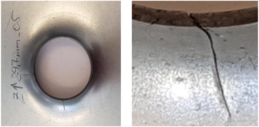
Local formability failure modes are an entirely different failure condition, where fractures occur out of the plane of the sheet in response to concentrated deformation created when forming localized features like stretch flanges, extruded holes, or bends around a radius too small for the selected steel grade. These failures typically occur without any observable thinning or necking (Figure 1). Forming simulation software that considers only the forming limit curve or maximum thinning as the failure criteria cannot predict local formability failures.
Figure 1: A fracture related to insufficient local formability. Note the lack of thinning near the fracture. H-5
Cutting conditions and edge stresses developed in blanking and slitting operations play a significant role in limiting local formability. Trim steel clearances, shear angles, trim steel materials, tool sharpness and design, steel rolling direction, and part design considerations are all important (Figure 2).
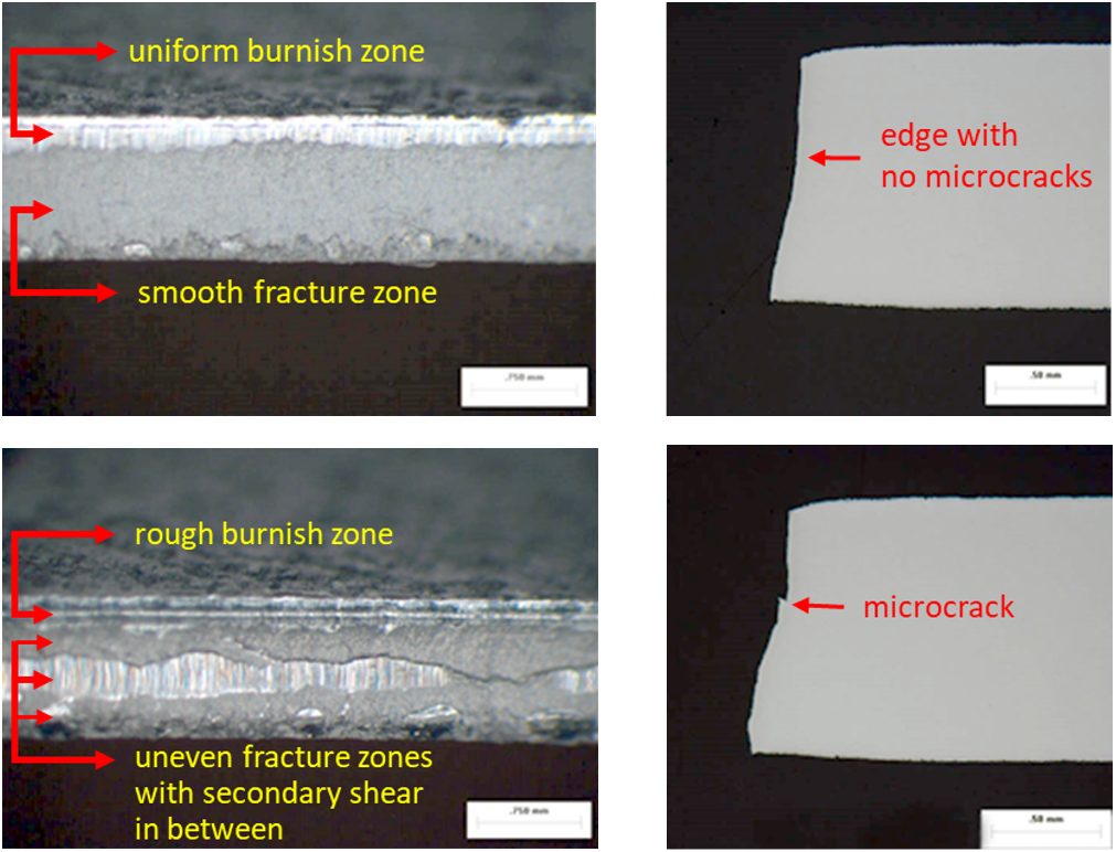
Figure 2: Cut edge uniformity influences edge quality.U-6
The absence of global thinning leading to the onset of localized necking highlights the importance of clearly defining the actual mode of failure before trying to identify possible solutions. Examination of the edge of the part where the failure is occurring is the best way to accomplish this. Figure 3 shows a photo of a typical local formability related edge fracture where no observable thinning/necking before fracture occurs.
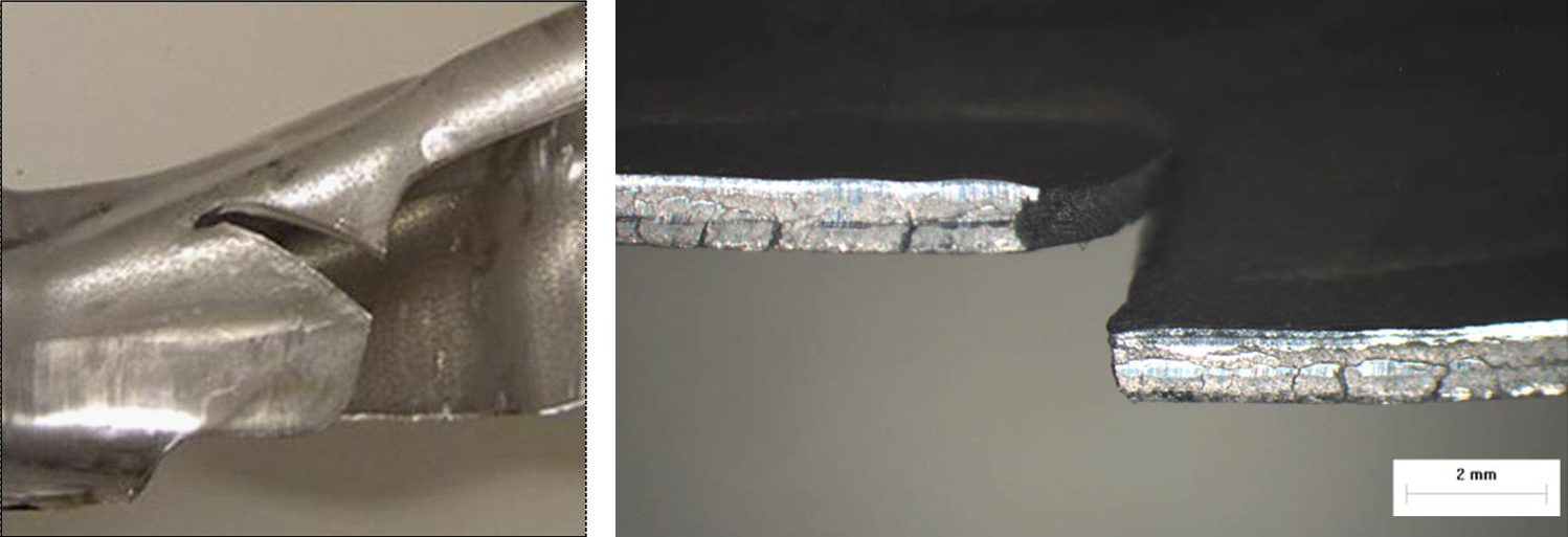
Figure 3: A typical local formability edge fracture viewed from different angles, with no appreciable thinning prior to fracture.U-6
Some AHSS grades are more prone to these local formability failures. A reduced hardness difference between microstructural phases appears to improve local formability. At a given tensile strength level, there may be grades with improved global formability, improved local formability, or a balanced approach available. Choosing the optimum grade requires understanding of the manufacturing die process and the functionality requirements associated with the part and its application.
Figure 4 shows an edge fracture on a DP980 rocker panel. This panel experienced edge fractures during production, occurring in embossments along the edge of the part, with no evidence of necking at the fracture site. This is a classic local formability failure, reinforcing the need to inspect the conditions at the fracture zone of AHSS to determine whether the root failure is global or local formability. Process and die solutions differ based on the mode of failure.

Figure 4: Classic local formability related edge fracture on an embossment within a DP980 part.U-6
Grade dependency is highlighted in Figure 5, which compares edges of HSLA 50SK on the left and DP500Y/780T on the right after stretch-bend testing under conditions to produce fracture. The HSLA sample shows the characteristic thinning down associated with necking. The DP steel did not have a visible neck at the failure location.S-11
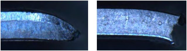
Figure 5: Left: HSLA 50SK, showing thinning at the fracture location, which is typical for global formability failures. Right: DP 500Y/780T, showing no thinning at the fracture location, which is typical for local formability failures.S-11
Mechanical tests now being employed to better quantify and characterize the unique local formability related failure modes associated with AHSS include:
Fracture-Limited Formability = Local Formability
In general, most sheet metal stamping failures result from exceeding the necking limit, and are termed global formability failures. However, there are important conditions which promote fracture before first developing a neck. These are of particular concern since such fractures cannot be predicted or anticipated based on conventional FLC and grid strain analysis techniques. Recent advances in metal forming software codes now allow input of appropriate data which substantially aids in these efforts. Still, there is no universally accepted shape of the Fracture Limit Curve.
Local Formability: Bending
Researchers discovered that all the steel through the sheet thickness must exceed the forming limit for necking to begin. In tight bends where the inner surface is compressed, strains never reach the critical strains in the conventional forming limit curve, which is why necking is not seen on the outer bend surface above a critical r/t level, or the ratio between the radius and the thickness.
However, as strength increases, the fracture limit is closer to the necking limit determined by the FLC. Advanced High Strength Steels are even more sensitive to local formability failures due to the localization of strains which occur at the interface between hard and soft phases in the microstructure.
On thin, wide sheet, bending strains on the metal surface plot along the axis of plane strain. The Fracture Limit Curve in this location is higher than the necking Failure Limit Curve, but since the critical strains only need to be reached on the outermost surface, higher-strength steels have a greater risk of experiencing bending fractures. In these cases, the material fracture limit becomes the effective forming limit in deformation modes with severe through-thickness strain gradients, and this is not considered in the traditional FLD.
Local Formability: Sheared Edge Expandability (Hole Expansion)
In a hole expansion test, the strains at the edge of the expanding hole follow a uniaxial strain path until reaching the fracture limit. In lower-strength steels with clean, machined (undamaged) edges, expansion ratios over 300% might be possible. As mentioned above, higher-strength steels have a lower fracture limit. Still, undamaged machined edges provide the best conditions for high hole expansion.
Cutting operations like blanking, shearing, and punching all damage the edge and lowers the fracture limit, meaning that the fracture limit might be reached at even lower strains. Strain localization occurring at the interface between hard and soft microstructural phases highlight why some grades have still lower critical strains.
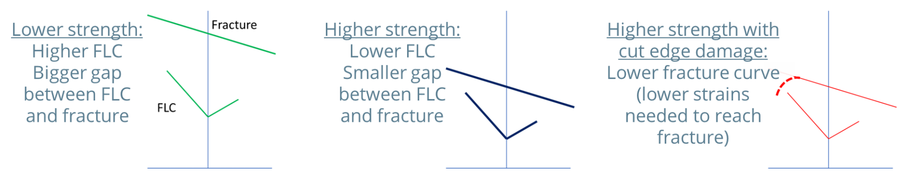
Figure 6: Higher-strength steels have a smaller gap between the necking Forming Limit Curve and the Fracture Limit Curve.
Summary of Global Formability
- The resistance to localized thinning (necking) is the key to global formability.
- Stamped parts get progressively thinner as the press stroke approaches bottom-dead-center. Rapid thinning in critical areas lead to the onset of localized necking. Global formability promotes the ability to reach deeper draw depths before initiation of necking.
- Measures of global formability include the work-hardening exponent (n-value), the uniform elongation value, and the total elongation value determined in a tensile test, along with the forming limit curve (FLC).
- Global formability failures occur when a through-thickness volume of the formed sheet steel exceeds this forming limit and begins to neck.
Necking failure typically should not occur if the global formability limit is exceeded on only the outer surface of steel bent over a radius or expanded at a cut edge and not through the full thickness of the metal.
- Uniform elongation measures the resistance to local necking. The global formability limit corresponds to Uniform Elongation in the strain state achieved in a tensile test sample. The Forming Limit Curve (FLC) encompasses all strain states.
- For mild and conventional high strength steels, there is a large difference between the necking limit and the ultimate fracture limit. This corresponds to the difference between Uniform Elongation and Total Elongation in a tensile test, where the value of total elongation is typically twice that of uniform elongation.
Summary of Local Formability
- The resistance to fracture is the key to local formability.
- Local formability promotes fracture resistance in response to creating local product features like stretch flanges, extruded holes, and tight-radius bends.
- Local formability tests which evaluate the stretchability of appropriately prepared edges by deforming them with a punch may have limited reproducibility between labs due to the influence of different sample preparation methods. Determining parameters like True Fracture Strain, Reduction in Area at Fracture, or Thickness Strain at Fracture with a well-defined tensile test typically results in repeatable and reproducible values.
- Local formability failure occurs when strains at the surface or edge exceed the ultimate fracture limit, a value that is higher than the necking limit determined by the Forming Limit Curve.
- Local formability failures occur more frequently on higher strength steels partly because of a smaller difference between the necking limit determined by the Forming Limit Curve and ultimate fracture limit.
- Work hardening and damage from edge preparation methods like shearing further reduce edge formability to values typically lower than indicated by the Forming Limit Curve, especially for AHSS. The strain localization at the interface between hard and soft phases in AHSS also contribute to an increased risk of local formability failures.
- The lack of a localized neck is a characteristic trait associated with of local formability failures.
![Mechanical Properties]()
Mechanical Properties
Necking: Diffuse Neck and Local Neck
A tensile bar increases in length as it is pulled, with a concurrent reduction in width and thickness. The cross section is rectangular in shape through uniform elongation. After uniform elongation, however, strains concentrate in the reduced section of the tensile test sample, resulting in a non-uniform section of reduced width. This region is known as a diffuse neck. The diffuse neck further accentuates and accelerates the cross-section reduction, leading to a concentration of strains within this region.
A local neck is a narrow band in the sheet metal part that is thinner than its surroundings (Figure 1). This local or through-thickness neck occurs shortly before the traditional fracture of the specimen. When the local neck begins, deformation stops in the remainder of the stamping. In a tensile bar, no deformation occurs along the width of the neck – only increased elongation and thinning. A local neck prevents a deeper section from being formed and serves as a crack initiation site. Additional loading, including fatigue loading during the life of the part, may cause a neck to progress to fracture (Figure 2). The strains resulting in a local neck are defined by the Forming Limit Curve, or FLC.

Figure 1: A local neck prevents forming a deeper section and serves as a crack initiation site.

Figure 2: Necking and fracture on a sample formed with a hemispherical dome.S-57
Traditional methods of detecting the onset of necking include tactile or visible sensing of the groove of the neck. Researchers are focusing on the use of non-contact approaches to define a neck. ISO 12004-2 calls for a polynomial fit of data outside the neck, but results from this method are a function of the order of the polynomial as well as the geometry of the tooling and the blank.
Using Digital Image Correlation allows for the detection in curvature evolution in the area that subsequently develops into a neck. The signature is detected for the many types of AHSS grades tested as well as other sheet metals, and correlates well with other methods. Citation S-57 presents an overview of the technique, with greater detail covered in Citations M-19 and S-58. Using the surface data geometry as measured by DIC to detect the true onset of necking enables better and more efficient use of AHSS grades through more reliable knowledge of their actual limits.
![Mechanical Properties]()
Mechanical Properties
Total Elongation to Fracture
Deformation continues in the local neck until fracture occurs. The amount of additional strain that can be accommodated in the necked region depends on the microstructure. Inclusions, particles, and grain boundary cracking can accelerate early fracture. Total elongation is measured from start of deformation to start of fracture. Two extensometer gauge lengths are commonly used: A50 (50mm or 2 inches) and A80 (80 mm).
In the past, limited automation and measurement equipment necessitated the use of a non-repeatable technique defined in ASTM E8A-24 and ISO 6892-1I-7 as “elongation after fracture.” Here, the operator attempts to position the two fractured strips back together and hand measures the distance between two gauge marks on the sample.
Tensile testing combined with data acquisition systems are much more commonplace today. According to ASTM E8, the elongation at fracture shall be taken as the strain measured just prior to when the force falls below 10 % of the maximum force encountered during the test. Both elastic strains and plastic strains are included in the measurement.

Figure 1 : Total elongation is measured from start of deformation to start of fracture.