Uniform Elongation

Uniform Elongation

During a tensile test, the elongating sample leads to a reduction in the cross-sectional width and thickness. The shape of the engineering stress-strain curve showing a peak at the load maximum (Figure 1) results from the balance of the work hardening which occurs as metals deform and the reduction in cross-sectional width and thickness which occurs as the sample dogbone is pulled in tension. In the upward sloping region at the beginning of the curve, the effects of work hardening dominate over the cross-sectional reduction. Starting at the load maximum (ultimate tensile strength), the reduction in cross-sectional area of the test sample overpowers the work hardening and the slope of the engineering stress-strain curve decreases. Also beginning at the load maximum, a diffuse neck forms usually in the middle of the sample.

Figure 1: Engineering stress-strain curve from which mechanical properties are derived.

Figure 1: Engineering stress-strain curve from which mechanical properties are derived.


The elongation at which the load maximum occurs is known as Uniform Elongation. In a tensile test, uniform elongation is the percentage the gauge length elongated at peak load relative to the initial gauge length. For example, if the gauge length at peak load measures 61 mm and the initial gauge length was 50mm, uniform elongation is (61-50)/50 = 22%.

Schematics of tensile bar shapes are shown within Figure 1. Note the gauge region highlighted in blue. Up though uniform elongation, the cross-section has a rectangular shape. Necking begins at uniform elongation, and the cross section is no longer rectangular.

Theory and experiments have shown that uniform elongation expressed in true strain units is numerically equivalent to the instantaneous n-value.

Deformation Prior to Uniform Elongation is Not Uniformly Distributed

Conventional wisdom for decades held that there is a uniform distribution of strains within the gauge region of a tensile bar prior to strains reaching uniform elongation. Traditional extensometers calibrated for 50-mm or 80-mm gauge lengths determine elongation from deformation measured relative to this initial length. This approach averages results over these spans.

The advent of Digital Image Correlation (DIC) and advanced processing techniques allowed for a closer look. A studyS-113 released in 2021 clearly showed that each of the 201 data points monitored within a 50 mm gauge length (virtual gauge length of 0.5-mm) experiences a unique strain evolution, with differences starting before uniform elongation.

Figure 2 caption: Strain evolution of the 201 points on the DP980 tensile-test specimen exhibits divergence beginning before uniform elongation—counter to conventional thinking.

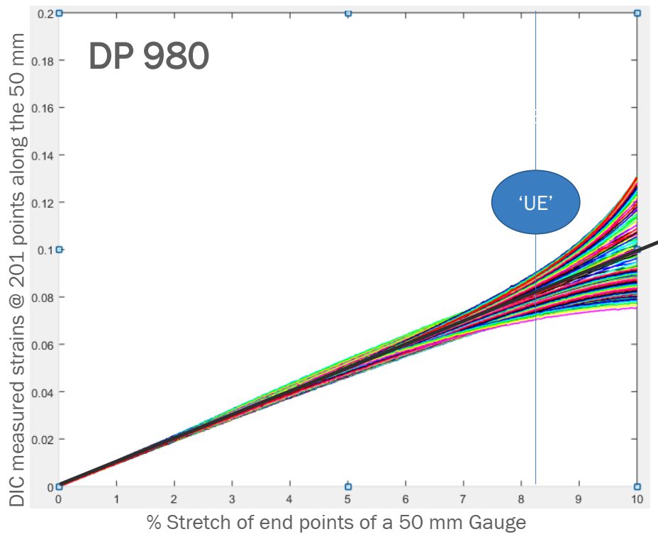
Figure 2: Strain evolution of the 201 points on the DP980 tensile-test specimen exhibits divergence beginning before uniform elongation—counter to conventional thinking.S-113


Uniform Elongation

Necking

Necking: Diffuse Neck and Local Neck

A tensile bar increases in length as it is pulled, with a concurrent reduction in width and thickness. The cross section is rectangular in shape through uniform elongation. After uniform elongation, however, strains concentrate in the reduced section of the tensile test sample, resulting in a non-uniform section of reduced width. This region is known as a diffuse neck. The diffuse neck further accentuates and accelerates the cross-section reduction, leading to a concentration of strains within this region.

A local neck is a narrow band in the sheet metal part that is thinner than its surroundings (Figure 1). This local or through-thickness neck occurs shortly before the traditional fracture of the specimen. When the local neck begins, deformation stops in the remainder of the stamping. In a tensile bar, no deformation occurs along the width of the neck – only increased elongation and thinning. A local neck prevents a deeper section from being formed and serves as a crack initiation site. Additional loading, including fatigue loading during the life of the part, may cause a neck to progress to fracture (Figure 2). The strains resulting in a local neck are defined by the Forming Limit Curve, or FLC

Figure 1:  A local neck prevents forming a deeper section and serves as a crack initiation site.

Figure 1:  A local neck prevents forming a deeper section and serves as a crack initiation site.


Figure 2: Necking and fracture on a sample formed with a hemispherical dome.S-57

Figure 2: Necking and fracture on a sample formed with a hemispherical dome.S-57


Traditional methods of detecting the onset of necking include tactile or visible sensing of the groove of the neck. Researchers are focusing on the use of non-contact approaches to define a neck. ISO 12004-2 calls for a polynomial fit of data outside the neck, but results from this method are a function of the order of the polynomial as well as the geometry of the tooling and the blank.

Using Digital Image Correlation allows for the detection in curvature evolution in the area that subsequently develops into a neck. The signature is detected for the many types of AHSS grades tested as well as other sheet metals, and correlates well with other methods. Citation S-57 presents an overview of the technique, with greater detail covered in Citations M-19 and S-58. Using the surface data geometry as measured by DIC to detect the true onset of necking enables better and more efficient use of AHSS grades through more reliable knowledge of their actual limits.