Laser Welding
This article is a summary of the paper entitled, “IMPROVEMENT OF DELAYED CRACKING IN LASER WELD OF AHSS AND 980GEN3 STEELS”, by Linlin Jiang, Kyle Kram, and Chonghua Jiang.L-62
Researchers from AET Integration, Inc. worked on developing welding techniques that mitigated delayed cracking issues when laser welding Advanced High-Strength Steels (AHSS) and 3rd Gen AHSS. Stitch welds are most likely to have delayed cracking issues therefore the test specimen were cross tension samples with stitch welds. The test was run with ten specimens for each material with the same parameters. The specimen were visually inspected after welding in intervals from 30 min to 12 hours for 48 hours. The specimen were then inspected using X-ray analysis, cross-sectioning, and scanning electron microscope (SEM) analysis. Cracks were observed in the weld schedules used in Figure 1 and 2, and no cracking was observed in the welding schedules developed by researchers as seen in Figure 3 and 4 by altering parameters such as laser power, travel speed, beam oscillation, and defocusing techniques. The techniques are currently patent-pending and were not discussed in the research paper. Further validation tests on 3rd Gen steels is expected in the future.

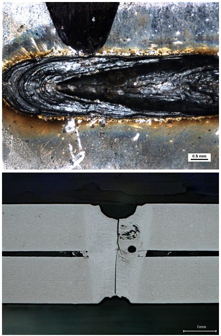
Figure 1: Delayed Crack in Weld of Material A. (Top) Crack from top surface, (Bottom) Cross Section of Crack.L-62

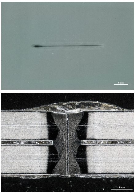
Figure 6: Delayed Cracking in Weld of Material B, (Top) X-ray, (Bottom) Cross section of crack.L-62

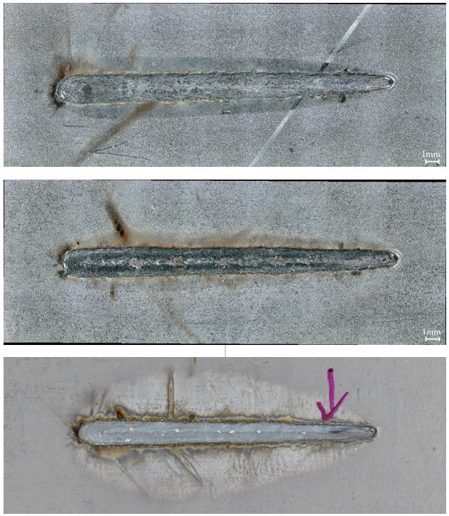
Figure 3: Examples of Visual Inspection Photographs. (Top) Top surface, Material A, (Middle) Top surface, Material B, (Bottom) Top surface, Material C.L-62

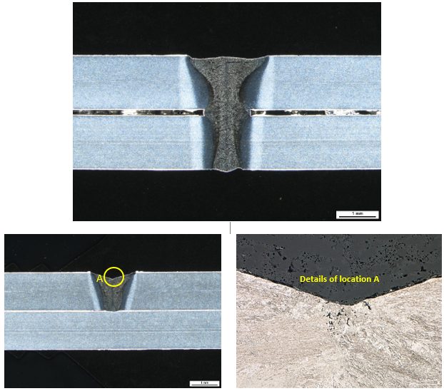
Figure 4: Examples of Cross Section Photographs. (Top) Cross section of weld center, Material A; (Bottom) Cross section of weld crater, Material A.L-62
Testing and Characterization
Delayed cracking caused by hydrogen embrittlement results in decreased toughness, ductility, and load-bearing capacity of a material. It is a concern with some Advanced High-Strength steel (AHSS) grades.
Three triggers must be present for there to be an embrittlement risk:
- Use of a susceptible material, such as steel with tensile strength above approximately 1000 MPa and/or the presence of retained austenite in the microstructure,
- An environment or processing step where hydrogen is available to diffuse into the steel, and
- Presence of a high stress condition, either from forming or during product usage and life cycle.
The interaction between hydrogen and the steel crystallographic structure in the presence of these conditions limits the ability of the steel to deform under load. The steel part will fracture at a lower stress than is anticipated under other conditions. Of particular concern is that fracture may not occur at the time of stamping, since hydrogen can diffuse out of the lattice over time.
High strain areas on parts formed from AHSS are at increased risk for delayed cracking, since the distorted crystallographic lattice allows for an increased hydrogen solubility. Cut edges are especially troublesome, since the shearing operation work hardens the steel (increasing strength) and damages the microstructure (increasing strain).
AHSS grades that contain retained austenite are also at increased risk for delayed cracking from hydrogen embrittlement. Stamping strains provide the driving force for the TRIP effect, where austenite coverts to martensite. The austenite crystallographic lattice allows for increased hydrogen solubility, so the TRIP effect creates a hydrogen-rich high strength martensite – conditions that promote a greater risk of embrittlement.
Sources of hydrogen include:
- Breakdown of mill or press applied lubricants,
- Annealing or heat treating atmospheres, and
- Electrochemical operations in steel mills or vehicle production such as pickling, electrogalvanizing, welding, phosphate coating, and paint pretreatment, such as e-coating.
Actions to minimize the risk of hydrogen embrittlement includes not over-pickling the surface prior to coating (since pickling uses an acid), heat treating in dew-point controlled atmospheres (below -10 °C or even lower for higher strength grades), and using the e-coating operation as a means to degas the steel.
Global steelmakers take alloying and processing approaches that are specific to their particular infrastructure and equipment. The same grade from two different steelmakers will likely use different alloying approaches. This may lead to different hydrogen embrittlement risks, as well as different tensile property ranges. Use caution when switching suppliers for all AHSS grades.
The procedures to characterize delayed fracture resistance typically involve using a machined sample, pre-strained and placed in an acidic solution for a defined time. SAE J3215S-94 is one such procedure.
Note that cracking in simulative tests does not necessarily indicate that parts made from that material would crack in an automotive environment due to the specific conditions that need to be present for hydrogen embrittlement to occur. When selecting any AHSS, results from simulative tests should be considered in conjunction with the forming and processing history of the steel, the strain state of the formed and processed part, and the operating environment of the part.
Testing and Characterization
Many demands are placed on automotive body structures which influence the material selection process. The impact on safety, manufacturability, and longevity are among the most critical, with each of these balanced against cost and environmental concerns.
Formed sheet metal products experience a complex series of deforming, cutting, and joining before being placed in a body structure, where these components will be subjected to complex loading conditions during the product life cycle. Understanding the failure limits and the conditions which produce failure allows for the design of body structures which can withstand these demands.
Testing helps determine whether a metal is suitable for its intended use. Different tests characterize specific performance aspects. Historically, manufacturers relied on tensile testing to understand metal flow. However, new tests help us understand the behavior of new steel grades and their interactions more thoroughly with new manufacturing technologies.


