Solid State Welding
Introduction
Solid-State welding refers to a family of processes that produce welds without the requirement for molten metal. Solid-state welding theory emphasizes that the driving force for two pieces of metal to spontaneously weld (or form a metallic bond) to each other exists if the barriers (oxides, contaminants, and surface roughness) to welding can be eliminated. All solid-state welding processes are based on this concept, and use some combination of heat, pressure, and time to overcome the barriers. Approaches include friction, diffusion, explosion, and ultrasonic welding.
Since there is no melting, there is no chance of forming defects such as porosity or slag inclusions which are only associated with fusion welding processes. Solid-state welding processes also require no filler materials, and in some cases, can be quite effective at welding dissimilar metals that cannot be welded with conventional processes due to metallurgical incompatibilities. The equipment is typically very expensive, and some processes involve significant preparation time of the parts to be welded. Most of these processes are limited to certain joint designs, and some of them are not conducive to a production environment. Non Destructive Testing processes do not always work well with solid-state welding processes because of the difficulties of distinguishing a true metallurgical bond with these techniques.
In this section you’ll find examples of three types of solid state welding processes: Friction, High-Frequency for tubes and pipe and Magnetic Pulse. Generally these are characterized as follows. Click to the specific menu for details.
Friction Welding Processes
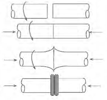
Figure 1: Basic steps of both inertia and CD friction welding.
This family of processes relies on significant plastic deformation or forging action to overcome the barriers to solid-state welding. Frictional heating dominates at the beginning of the process, followed by the heating due to plastic deformation once the forging action begins. The friction welding processes which use rotation of one part against another are inertia and continuous (or direct)-drive friction welding. These are the most common of the friction welding processes and are ideal for round bars or tubes. In both inertia and Continuous-Drive (CD) friction welding, one part is rotated at high speeds relative to the other part (Figure 1). They are then brought together under force creating frictional heating which softens (reduces the YS) the material at and near the joint to facilitate the forging action, which, in turn, produces further heating. Following a sufficient amount of time to properly heat the parts, a high upset force is applied which squeeze the softened hot metal out into the “flash”. Any contaminants are squeezed out as well as the weld is formed. The flash is usually removed immediately after welding while it is still hot.A-11, P-6
High Frequency Tube/Pipe Welding
HF welding processes rely on the properties of HF electricity and thermal conduction, which determine the distribution of heat in the workpieces. HF contact welding and high-frequency induction welding are used to weld products made from coil, flat, or tubular stock with a constant joint symmetry throughout the length of the weld.
Magnetic Pulse Welding (MPW)
MPW is a solid-state process that uses electromagnetic pressure to accelerate one workpiece to produce an impact against another workpiece. The metallic bond created by this process is similar to the bond created by explosion welding. MPW, also known as electromagnetic pulse or magnetic impact welding, is highly regarded for the capability of joining dissimilar materials.
Resistance Spot Welding
Parameter Guidelines
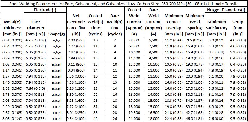
In summary, Tables 1 and 2 provide the AWS C1.1 Spot Welding Parameter Guidelines link to Recommended Practices for Resistance Welding. These general guidelines can be used to approximate which parameters can be used to begin the Resistance Spot Welding (RSW) process of a specific part thickness. From the recommended parameters, changes can be made on a specific stack-up to ensure an acceptable strength and nugget size for a particular application. Additionally, more complicated RSW parameter guidelines using a pulsation welding schedule with AC 60 Hz for welding AHSS is included in Table 3.
Table 1: Spot welding parameters for low-carbon steel 350-700 MPa (AHSS).A-14
- Use of coated parameters recommended with the presence of a coating at any faying surface.
- These recommendations are based on available weld schedules representing recommendations from resistance welding equipment suppliers and users.
- For intermediate thicknesses parameters may be interpolated.
- Minimum weld button shear strength determined as follows:
- ST = ((-8.83×10⁻⁷ × S2 + 1.34×10⁻³ × S + 1.514) × S × 4t1.5)/1000
- ST = Shear Tension Strength (kN)
- S = Base Metal Tensile Strength (MPa)
- t = Material Thickness (mm)
- Metal thicknesses represent the actual thickness of the sheets being welded. In the case of welding two sheets of different thicknesses, use the welding parameters for the thinner sheet.
- Welding parameters are applicable when using electrode materials included in RWMA Classes 1 , 2, and 20.
- Electrode shapes listed include: A-pointed, B-domed, E-truncated, F-radiused. Figure 2 shows these shapes.
- The use of Type-B geometry may require a reduction in current and may result in excessive indentation unless face is dressed to specified diameter.
- The use of Type F geometry may require an increase in current.
- Welding parameters are based on single-phase AC 60 Hz equipment.
- Nugget diameters are listed as:
- Minimum diameter that is recommended to be considered a satisfactory weld.
- Initial aim setup nugget diameter that is recommended in setting up a weld station to produce nuggets that consistently surpass the satisfactory weld nugget diameter for a given number of production welds.
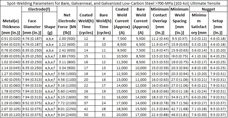
Table 2: Spot welding parameters for low-carbon steel >700 MPa (AHSS). A-14
- Use of coated parameters recommended with the presence of a coating at any faying surface.
- These recommendations are based on available weld schedules representing recommendations from resistance welding equipment suppliers and users.
- For intermediate thicknesses parameters may be interpolated.
- Minimum weld button shear strength determined as follows:
- ST = ((-8.83×10⁻⁷ × S2 + 1.34×10⁻³ × S + 1.514) × S × 4t1.5)/1000
- ST = Shear Tension Strength (kN)
- S = Base Metal Tensile Strength (MPa)
- t = Material Thickness (mm)
- Metal thicknesses represent the actual thickness of the sheets being welded. In the case of welding two sheets of different thicknesses, use the welding parameters for the thinner sheet.
- Welding parameters are applicable when using electrode materials included in RWMA Classes 1, 2, and 20.
- Electrode shapes listed include: A-pointed, B-domed, E-truncated, F-radiused. Figure 2 shows these shapes.
- The use of Type-B geometry may require a reduction in current and may result in excessive indentation unless face is dressed to specified diameter.
- The use of Type F geometry may require an increase in current.
- Welding parameters are based on single-phase AC 60 Hz equipment.
- Nugget diameters are listed as:
- Minimum diameter that is recommended to be considered a satisfactory weld.
- Initial aim setup nugget diameter that is recommended in setting up a weld station to produce nuggets that consistently surpass the satisfactory weld nugget diameter for a given number of production welds.
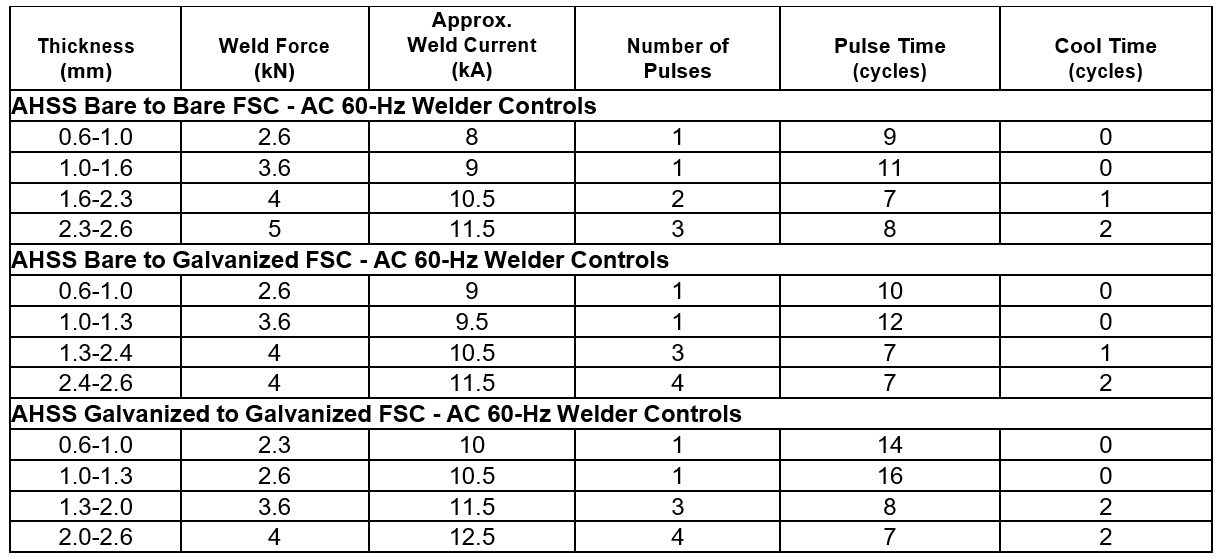
Table 3: AHSS bare-to-bare, bare-to-galvanized, Galvanized-to-galvanized RSW parameters for pulsating AC 60 Hz.A-14
Heat, Material and Thickness Balances
The heat input in Resistance Spot Welding (RSW) is defined as:
Heat Input = I2Rt
where: I is welding current
R is total resistance, and
t is weld time
The heat input must be changed depending on the gauge and grade of the steel. Compared to low strength steel at a particular gauge, the AHSS at the same gauge will need less current. Similarly, the thin gauge material needs less current than thick gauge. Controlling the heat input according to the gauge and grade is called heat balance in RSW.
For constant thickness, Table 1 shows steel classification based on strength level. With increasing group numbers, higher electrode force, longer weld time, and lower current are required for satisfactory RSW. Material combinations with one group difference can be welded with little or no changes in weld parameters. Difference of two or three groups may require special considerations in terms of electrode cap size, force, or type of power source.
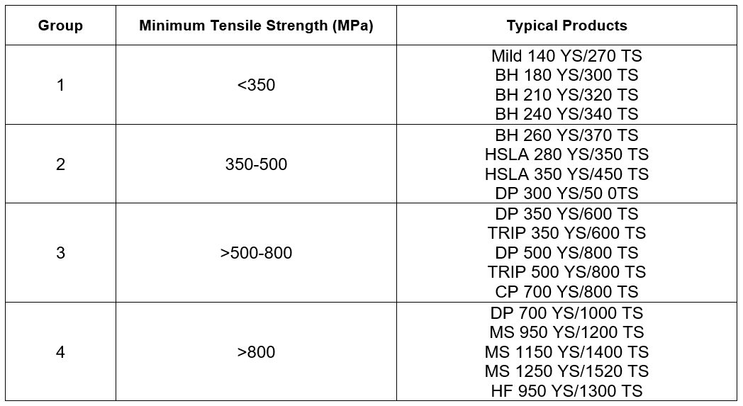
Table 1: Steel classification for RSW purposes.A-11
For a particular steel grade, changes in thickness may require adoption of special schedules to control heat balance. When material type and gauge are varied together, specific weld schedules may need to be developed. Due to the higher resistivity of AHSS, the nugget growth occurs preferentially in AHSS. Electrode life on the AHSS-side may be reduced due to higher temperature on this side. In general, electrode life when welding AHSS may be similar to mild steel because of lower operating current requirement due to higher bulk resistivity in AHSS. This increase in electrode life may be offset in production due to poor part fit up created by higher AHSS springback. Frequent tip dressing will maintain the electrode tip shape and help achieve consistently acceptable quality welds.
Welding Current Mode
AHSS can be welded with power sources operated with either AC or DC types (Figure 1). Middle-Frequency Direct-Current (MFDC) has an advantage over conventional AC due to both unidirectional and continuous current. These characteristics assist in controlling and directing the heat generation at the interface. Current mode has no significant difference in weld quality. It should be noted that both AC and DC can easily produce acceptable welds where thickness ratios are less than 2:1. However, some advantage may be gained using DC where thickness ratios are over 2:1, but welding practices must be developed to optimize the advantages. It also has been observed that nugget sizes are statistically somewhat larger when using DC welding with the same secondary weld parameters than with AC. Some studies have shown that welding with MFDC provides improvements in heat balance and weld process robustness when there is a thickness differential in AHSS (as shown in Figure 2). DC power sources have been reported to provide better power factors and lower power consumption than AC power sources. Specifically, it has been reported that AC requires about 10% higher energy than DC to make the same size weld.L-7
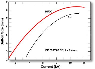
Figure 1: Range for 1.4-mm DP 350/600 CR steel at different current modes with a single pulse.L-2
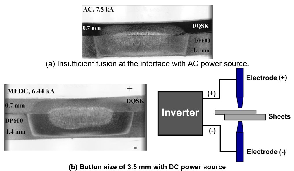
Figure 2: Effect of current mode on dissimilar-thickness stack-up.L-2
Consult safety requirements for your area when considering MFDC welding for manual weld gun applications. The primary feed to the transformers contains frequencies and voltages higher than for AC welding.
Back To Top