Citations
Citation:
W-9. Luke Walker, Colleen Hilla, Menachem Kimchi, and Wei Zhang, “Process, Microstructure and Fracture Moe of Thick Stack-Ups of Aluminum Alloy to AHSS Dissimilar Spot Joints”, AWS Sheet Metal Welding Conference XIX, Livonia, Mich., Nov. 2021.
Citations
Citation:
L-62. Linlin Jiang, Kyle Kram, and Chonghua Jiang, “IMPROVEMENT OF DELAYED CRACKING IN LASER WELD OF AHSS AND 980GEN3 STEELS”, AWS Sheet Metal Welding Conference XIX, Livonia, Mich., Nov. 2021.
Solid State Welding
Magnetic Pulse Welding (MPW) is a solid-state process that uses electromagnetic pressure to accelerate one workpiece to produce an impact against another workpiece. The metallic bond created by this process is similar to the bond created by explosion welding. MPW, also known as electromagnetic pulse or magnetic impact welding, is highly regarded for the capability of joining dissimilar materials.
Physics of the Process
Electromagnetic metal processing was developed in the late 1800s, and in succeeding years most applications for this technology were in metal forming. It was not recognized as a viable welding process, but a substantial renewal of interest has occurred recently in the further development of this technology for welding.
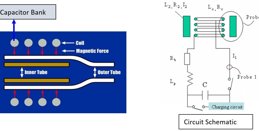
Fundamentally, both metal forming and welding use the same underlying physics. The process is driven by the primary circuit. A significant amount of energy, usually between 5 and 200 kJ, (1,124- and 44,962-lb force) is stored in capacitors charged to a high voltage that may range between 3,000 and 30,000 V. The capacitors are then discharged through low-inductance and highly conductive bus bars into a coil, or actuator. The resulting current takes the form of a damped sine wave, characterized as a ringing inductance-resistance-capacitance circuit. Peak currents during this process range between tens of thousands and millions of Amperes (A), with pulse widths on the order of tens of microseconds. This creates an extremely intense transient magnetic field in the vicinity of the coil. The magnetic field induces eddy currents in any conductive materials nearby, in the opposite direction to the primary current. The opposing fields in the coil and workpiece result in a high repulsion force. This force drives the flyer, or driver, workpiece (the workpiece closest to the driving coil) at high velocity toward the target, the stationary workpiece, resulting in a high impact between the two metals.
The impact pressure drives away the surface contaminants and provides for the intimate contact of clean surfaces across the weld interface. Metallic bonding results from this contact. A schematic of the process is shown in Figure 1 and in the video which follows.
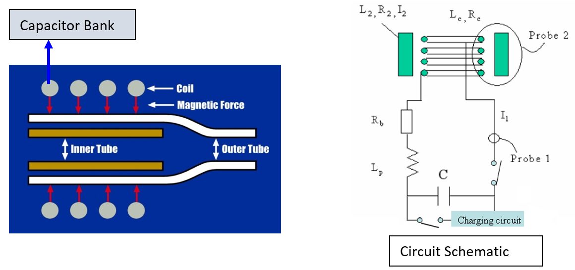
Figure 1: Basic diagram of the MPW process.
The following three elements are fundamental to achieving good magnetic pulse-welded joints:
- Correct welding machine parameters.
- Consideration of metal or material properties.
- Relative positioning of the flyer and the target workpieces.
Welding machine parameters determine the frequency and magnitude of the current waveform. High frequencies typically are favored for MPW. If the frequency is too low, the buildup of eddy currents in the flier workpiece will not be sufficient to achieve the velocities necessary for impact joining. The frequency is directly related to the electrical characteristics (LRC) of the circuit, including the capacitors and coil. Low system capacitances and inductances favor HF characteristics.
The properties of the workpiece metal, particularly of the flier, also contribute to determining the weldability of a given metal. Properties to be considered include electrical conductivity and strength. Metals with high electrical conductivity and low strength are most easily welded with the magnetic pulse process. Higher electrical conductivity facilitates greater induced currents in the flier workpiece, with correspondingly greater magnetic pressures. Lower YS facilitate displacements of the flier at lower magnetic pressures and are easier to accelerate to the required speed for welding. Carbon steel also can be welded when adjustments are made to the system power and frequency. Metals with relatively low electrical conductivity, such as austenitic stainless steels, are almost impossible to directly weld with the magnetic pulse process. They are readily welded, however, with the use of a driver plate. The driver plate is essentially a band of conductive material (typically Cu) wrapped around the low-conductivity flier. During welding, the driver reacts with the coil, pushing the actual flier to the necessary velocities for metallic bonding.A-11
Power Source
The essential component of an MPW system is a capacitor bank. The energy stored in the system can be determined from the size (capacitance) of the bank and the charge voltage using the following equation:

where:
E = Energy
C = Capacitance
V = Voltage
The energy is provided to the capacitors by a dedicated charging system. The capacity of the charging system largely controls the time required to charge the bank between subsequent welds. The charging circuit generally is actively cooled, allowing repeated use during production applications.
As previously mentioned, energy is transferred from the capacitors to the coil with an assembly of bus bars. Two considerations are key in the design of the bus bar assembly: it must have low inductance (in general, the majority of the system inductance should be at the coil), and low resistance contacts. When in use, the capacitors are charged relatively slowly to a predefined voltage. Once this voltage is reached, a fast-action switch is used to allow current flow to the coil. Switching typically is done using solid-state Silicon-Controlled Rectifiers (SCRs).A-11
Tubular Structures
MPW has great potential for joining tubular structures for automotive and aerospace applications and for fluid-carrying tubes. Examples of MPW tubular applications are shown in Figure 2. The process has several advantages that can significantly reduce manufacturing costs, summarized as follows:
1. HS joints can be produced that are stronger than the BM.
2. Leak-tight welds can be made.
3. High welding speeds, in the millisecond range make the process readily adapted to automation.
4. Dissimilar metals and difficult-to-weld materials, such as 303 stainless steel, can be joined.
5. Cold processing enables immediate handling.
6. Welds are made with no HAZ and minimum distortion.
7. Post-cleaning operations and Post Weld Heat Treatments (PWHT) are unnecessary.
8. The process is cost efficient because no filler metals or shielding gases are needed, and environmental costs are reduced.
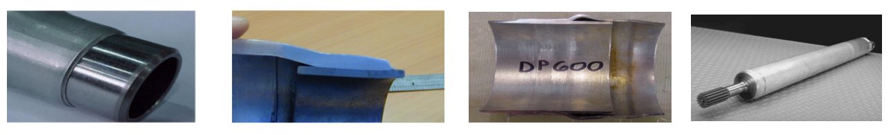
Figure 2: Examples of MPW tubular applications.
Applications
MPW has been successfully applied to various similar and dissimilar metal combinations. Materials with high conductivity, such as Al and Cu, are the easiest to weld with the magnetic pulse process. Al has been successfully welded to steel and stainless steel. Cu has been successfully welded to steel and stainless steel.
MPW has been used to join fuel pipes, fuel filters, exhaust system components, power cables, and for the construction of automotive body parts. The development of new applications of the MPW process continues, with the goal of advancing these applications to mass production. The process is achieving increased recognition for applications across the industrial spectrum.A-11
Safe Practices
The potential hazards of MPW include mechanical and electrical risks, noise, flash, and fumes.
Mechanical
The welding machine should be equipped with appropriate safety devices to prevent injury to the operator’s hands or other parts of the body. Initiating devices, such as push buttons or foot switches, should be arranged and guarded to prevent inadvertent actuation.
Machine guards, fixtures, and operating controls must prevent the operator from coming in contact with the coil and workpiece and must block or deflect the weld jet associated with the process.
Electrical
All doors and access panels on machines and controls must be kept locked or interlocked to prevent access by unauthorized personnel. The interlocks should interrupt the power and discharge all the capacitors through a suitable resistive load when the panel door is open.
Personal Protection
Appropriate guards should be in place to isolate the operator from the process. Operating personnel should wear ear protection when the welding operations produce high noise levels.
Additional information on safe practices for welding is provided in the latest edition of ANSI Safety in Welding, Cutting, and Allied Processes, Z49.1 published by AWS.
Back To Top
Solid State Welding
Fundamentals and Principles of HF Welding
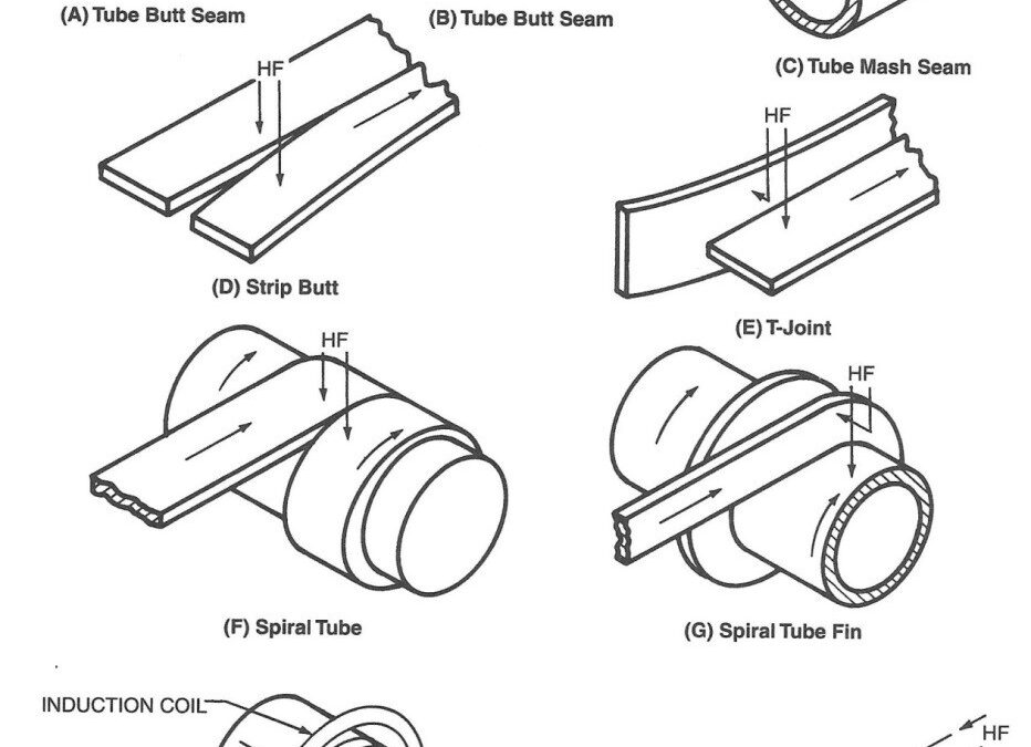
High Frequency (HF) welding processes rely on the properties of HF electricity and thermal conduction, which determine the distribution of heat in the workpieces. HF contact welding and high-frequency induction welding are used to weld products made from coil, flat, or tubular stock with a constant joint symmetry throughout the length of the weld. Figure 1 illustrates basic joint designs used in HF welding. Figures 1 (A) and (B) are butt seam welds; Figure 1 (C) is a mash seam weld produced with a mandrel, or backside/inside bar. Figure 1 (D) is a butt joint design in strip metal; and Figure 1 (E) shows a T-joint. Figures 1 (F) and (G) are examples of helical pipe and spiral-fin tube joint designs. Figure 1 (J) illustrates a butt illustrates a butt joint in pipe, showing the placement of the coil. Figure 4.L-6 (K) shows a butt joint in bar stock.
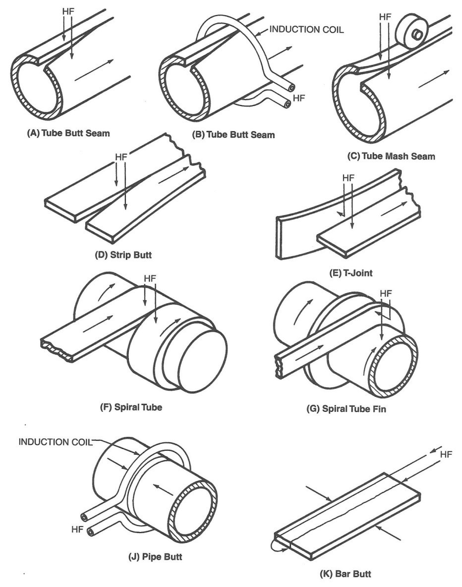
Figure 1: Basic joint designs for HF welds in pipe, tube, sheet, and bar stock.
HF current in metal conductors tends to flow at the surface of the metal at a relatively shallow depth, which becomes shallower as the electrical frequency of the power source is increased. This commonly is called the skin effect. The depth of electrical current penetration into the surface of the conductor also is a function of electrical resistivity, and magnetic permeability, the values of which depend on temperature. Thus, the depth of penetration also is a function of the temperature of the material. In most metals, the electrical resistivity increases with temperature; as the temperature of the weld area increases, so does the depth of penetration. For example, the resistivity of low-carbon steel increases by a factor of five between room temperature to welding temperature. Metals that are magnetic at room temperature lose the magnetic properties above the Curie temperature. When this happens, the depth of penetration increases drastically in the portion of metal that is above the Curie temperature while remaining much shallower in the metal that is below the Curie temperature. When these effects are combined in steel heated at a frequency of 400 kHz, the depth of current penetration is 0.05 mm (0.002 in.) at room temperature, while it is 0.8 mm (0.03 in.) at 800°C (1470°F). The depth of current penetration for several metals as a function of frequency is shown in Figure 2.
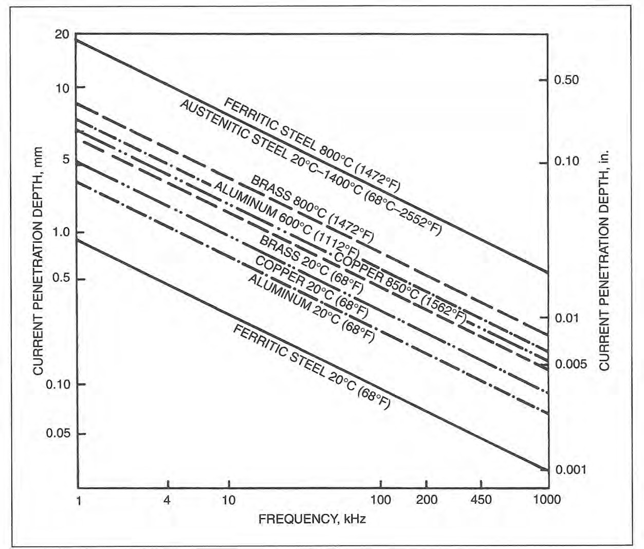
Figure 2: Effect of frequency on depth of penetration into various metals at selected temperatures.
The second important physical effect governing the HF welding process is thermal conduction of the heat generated by the electric currents in the workpiece. Control of the thermal conduction and of the penetration depth provides control of the depth of heating in the metal. Because thermal conduction is a time-dependent process, the depth to which the heat will conduct depends on the welding speed and the length of the electrical current path in the workpiece. If the current path is shortened or the welding speed is increased, the heat generated by the electric current in the workpiece will be more concentrated and intense. However, if the current path is lengthened or the welding speed is reduced, the heat generated by the electric current will be dispersed and less intense. The effect of thermal conduction is especially important when welding metals with high thermal conductivity, such as Cu or Al. It is not possible to weld these materials if the current path is too long or the welding speed is too slow. Changing the electrical frequency of the HF current can compensate for changes in welding speed or the length of the weld path, and the choice of frequency, welding speed, and path length can adapt the shape of the HAZ to optimize the properties of the weld metal for a particular application.A-11, A-15
Advantages/Disadvantages of HF Welding
A wide range of commonly used metals can be welded, including low-carbon and alloy steels, ferritic and austenitic stainless steels, and many Al, Cu, Ti, and Ni alloys.
Because the concentrated HF current heats only a small volume of metal at the weld interface, the process can produce welds at very high welding speeds and with high energy efficiency. HF can be accomplished with a much lower current and less power than is required for low-frequency or direct-current resistance welding. Welds are produced with a very narrow and controllable HAZ and with no superfluous cast structures. This often eliminates the need for Post-Weld Heat Treatment (PWHT).
Oxidation and discoloration of the metal and distortion of the workpiece are minimal. Discoloration may be further reduced by the choice of welding frequency. Maximum speeds normally are limited by mechanical considerations of material handling, forming and cutting. Minimum speeds are limited by material properties, excessive thermal conduction such that the heat dissipates from the weld area before bringing it to sufficient temperature, and weld quality requirements. The high process speed may also become a disadvantage if process settings are incorrect, as scrap can be generated at very high rates.
Considering the high processing speeds, with the high equipment cost required for HF welding, it is important to understand the amount of product needs for economic justification.
The fit-up of the surfaces to be joined and the way they are brought together are important if high-quality welds are to be produced. However, HF welding is far more tolerant in this regard than some other processes.
Flux is almost never used but can be introduced into the weld area in an inert gas stream. Inert gas shielding of the weld area generally is needed only for joining highly reactive metals such as Ti or for certain grades of stainless steel.A-11, A-15
Induction Seam Welding of Pipe and Tubing
The welding of continuous-seam pipe and tubing is the predominant application of HF induction welding. The pipe or tube is formed from metal strip in a continuous-roll forming mill and enters the welding area with the edges to be welded slightly separated. In the weld area, the open edges of the pipe or tube are brought together by a set of forge pressure rolls in a vee shape until the edges touch at the apex of the vee, where the weld is formed. The weld point occurs at the center of the mill forge rolls, which apply the pressure necessary to achieve a forged weld.
An induction coil, typically made of Cu tubing or Cu sheet with attached water- cooling tubes, encircles the tube (the workpiece) at a distance equal to one to two tube diameters ahead of the weld point. This distance, measured from the weld point to the edge of the nearest induction coil, is called the vee length. The induction coil induces a circumferential current in the tube strip that closes by traveling down the edge of the vee through the weld point and back to the portion of the tube under the induction coil. This is illustrated in Figure 3.
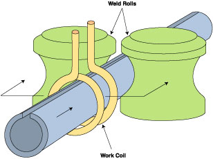
Figure 3: HF induction seam welding of a tube.
The HF current flows along the edge of the weld vee due to the proximity effect (see Fundamentals), and the edges are resistance-heated to a shallow depth due to the skin effect.
The geometry of the weld vee is such that its length usually is between one and one half to two tube diameters long. The included angle of the vee generally is between 3 and 7 degrees. If this angle is too small, arcing between the edges may occur, and it will be difficult to maintain the weld point at a fixed location. If the vee angle is too wide, the proximity effect will be weakened causing dispersed heating of the vee edges, and the edges may tend to buckle. The best vee angle depends on the characteristics of the tooling design and the metal to be welded. Variations in vee length and vee angle will cause variations in weld quality.
The welding speed and power source level are adjusted so that the two edges are at the welding or forge temperature when they reach the weld point. The forge rolls press the hot edges together, applying an upset force to complete the weld. Hot metal containing impurities from the faying surfaces of the joint is squeezed out of the weld in both directions, inside and outside the tube. The upset metal normally is trimmed off flush with the BM on the outside of the tube, and sometimes is trimmed from the inside, depending on the application for the tube being produced.A-11, A-15
The HF contact welding process provides another means of welding continuous seams in pipe and tubing. The process essentially is the same as that described above for induction welding and is illustrated in Figure 4. The major difference is that sliding contacts are placed on the tube adjacent to the unwelded edges at the vee length. With the contact process, the vee length generally is shorter than that used with the induction process. This is because the contact tips normally can be placed within the confines of the forge rolls where the induction coil must be placed sufficiently behind the forge rolls, so that the forge rolls are not inductively heated by the magnetic field of the induction coil. Because of the shorter vee lengths achievable with the contact process, an impeder often is not necessary, particularly for large-diameter tubes where the impedance of the current path inside the tube has significant inductive reactance.
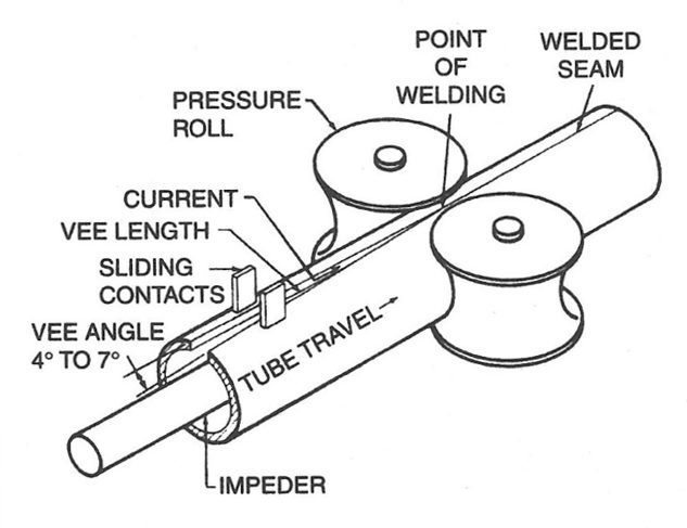
Figure 4: Joining a tube seam with HFRW using sliding contacts. Note: Vee length extends from point of welding to sliding contacts.
An impeder, which is made from a magnetic material such as ferrite, generally is required to be placed inside the tube. The impeder is positioned so that it extends about 1.5 to 3 mm (1/16 to 1/8 in.) beyond the apex of the vee and the equivalent of one to two workpiece diameters upstream of the induction coil. The purpose of the impeder is to increase the inductive reactance of the current path around the inside wall of the workpiece. This reduces the current that would otherwise flow around the inside of the tube and cause an unacceptable loss of efficiency. The impeder also decreases the magnetic path length between the induction coil and the tube, further improving the efficiency of power transfer to the weld point. The impeder must be cooled to prevent its temperature from rising above its Curie temperature, where it becomes nonmagnetic. For ferrite, the Curie temperature typically is between 170 and 340°C (340 and 650°F).A-11, A-15
Back To Top
Friction Stir Welding
Figure 1: Basic steps of both inertia and CD friction welding.
The Friction Stir Welding family of processes relies on significant plastic deformation or forging action to overcome the barriers to solid-state welding. Frictional heating dominates at the beginning of the process, followed by the heating due to plastic deformation once the forging action begins. The friction welding processes which use rotation of one part against another are inertia and continuous (or direct)-drive friction welding. These are the most common of the friction welding processes and are ideal for round bars or tubes. In both inertia and Continuous-Drive (CD) friction welding, one part is rotated at high speeds relative to the other part (Figure 1). They are then brought together under force creating frictional heating which softens (reduces the YS) the material at and near the joint to facilitate the forging action, which, in turn, produces further heating. Following a sufficient amount of time to properly heat the parts, a high upset force is applied which squeeze the softened hot metal out into the “flash”. Any contaminants are squeezed out as well as the weld is formed. The flash is usually removed immediately after welding while it is still hot.A-11, P-6
Friction Stir Welding
Friction Stir Welding (FSW) is a revolutionary new friction welding process that was developed in the early 1990s by the British Welding Institute (TWI). Whereas processes such as inertia and Continuous-Drive (CD) friction welding are primarily limited to round parts, FSW (Figure 2) produces solid-state friction welds using conventional joint design such as butt joints. FSW relies on the frictional heat created when a special non-consumable pin tool is rotated along the joint against the top of the two pieces being welded. As the process begins, frictional heating softens (or plasticizes) metal at the joint, facilitating a stirring action of plasticized metal. Further heating that is generated by the plastic deformation becomes the main source of heating as the weld progresses. The two videos following provide more insight on the process.
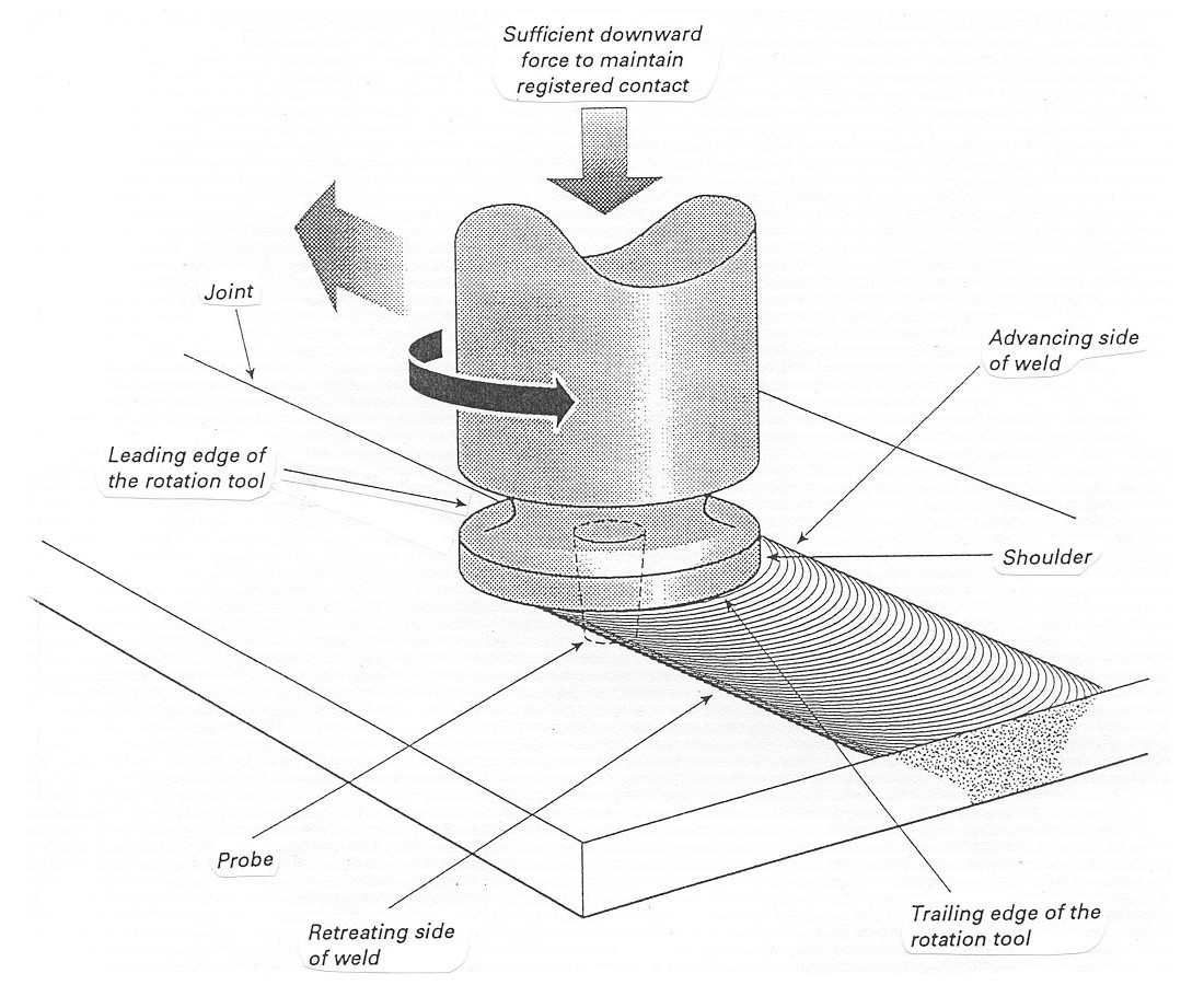
Figure 2: Friction Stir Welding
The pin tool for FSW consists of a shoulder and pin. The shoulder rests on the surface of the plates and provides most of the frictional heating. The pin partially penetrates the joint of the plates being welded. Within the stir zone itself, the plasticized hot metal flows around the pin and coalesces to form a weld. The primary purpose of the pin is to control the stirring action. A wide variety of pin tool designs and materials have been studied, including the use of Tungsten (W)-based materials, threaded pins, and cupped shoulders. As indicated on Figure 3, a slight push angle (<5 degrees) relative to the travel direction is typically used. Weld travel speeds are much slower than typical arc welding speeds. The process has limited industrial applications since it is still under development, especially in tool development.A-11, P-6
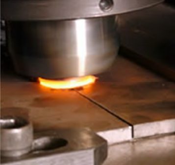
Figure 3: FSW typically uses a slight push angle
The FSW of hard metals (steel, Ti, Ni) has been made possible due to advancements in both tool design and tool materials. Tool material choices for AHSS applications include ceramic-based Polycrystalline Cubic Boron Nitride (PCBN) and refractory based Tungsten-Rhenium alloy (W-Re). PCBN is chosen because it is extremely wear resistant and has good thermal management. W-based material is chosen because it is very tough at room and welding temperatures and it is capable of being used for thick sections of steels.
Mechanical properties for FSW of AHSS cross-weld tensile specimens showed fully consolidated weld joints without discontinuities, but showed a drop-in weld ductility of about 10%, as seen in Figure 4.
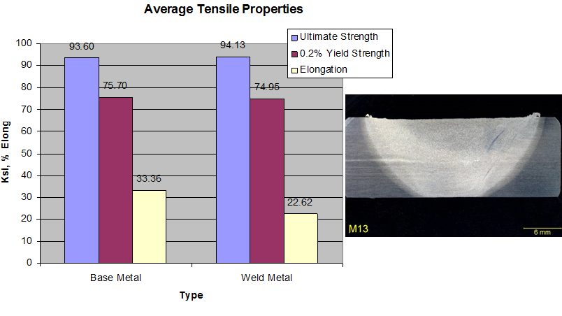
Figure 4: Mechanical properties of FSW for AHSS.
Friction Stir Spot Welding
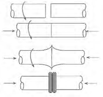
A variation of the FSW process is Friction Stir Spot Welding. This process was specifically developed for some automotive applications, including joining of AAl), Al-to-steel, and AHSS. The process steps are similar to FSW without the linear movement, thus creating a “spot”-type joint (Figure 5).O-1
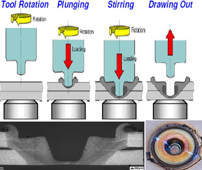
Figure 5: Process steps for friction stir spot welding (top) with the resultant weld profile (bottom).O-2
In summary, the advantages and limitations of friction welding processes are listed below.
- Advantages:
- No melting means no chance for solidification-related defects
- Filler materials are not needed
- Very few process variables result in a very repeatable process
- In the case of CD friction welding, can be deployed in a production environment
- Fine grain structure of friction welds typically exhibits excellent mechanical properties relative to the BM, especially when welding Al
- No special joint preparation or welding skill required
- Limitations:
- Equipment is very expensive
- Limited joint designs, and in the case of CD and inertia welding, parts must be symmetric
- FSW is very slow, and not conducive to high-speed
