Conventional blanking requires high press forces to shear the sheet metal. As steel strength increases, snap-through tonnage also increases, potentially leading to press and tooling damage. Over time, clearances may change, affecting edge quality. Shearing results in a work-hardened edge, and a shear affected zone know to decrease edge stretchability.
Blanking dies are often among the last dies completed prior to launch. Historically, this led to the use of hand-cut, steel-rule, or laser cut blanks during tryout. When laser cut blanks of AHSS are used during try out, the high hardness in the laser cut edges may damage the blank holder surface. Control the laser cutting parameters to reduce burrs and edge hardness. Deburr the edges of laser cut blanks prior to forming to minimize tool damage, especially when using soft tool materials like kirksite.
Using laser cut blanks during tryout offers product flexibility, since blank dimensions may change as part of the development process. However, upon completion of the blanking die, the dimensions cannot change without costly modifications.
Instead of using a blanking die, some companies are choosing to use laser blanking in production environments. Laser blanking eliminates the cost of blanking die construction and tooling maintenance. A dedicated blanking die for each part is no longer necessary – one laser blanking line can create blanks for multiple parts. Blank shape changes become another way to solve stamping formability problems. This approach also has the flexibility of incorporating blank size optimizations as part of the cost savings efforts targeted through the life of a stamping. Simple programming changes optimize nesting to take advantage of coil width capability improvements made by the sheet metal supplier.
Curved sections on blanking dies present design challenges related to cutting tool steel placement to avoid the creation of a notch at the mating point between two adjacent sections. Maintenance of sharp edges and consistent clearance is another challenge–advanced steel grades damage even the optimal cutting tool steels over time. Laser blanking avoids these concerns.
Multiple heads within the laser blanking system allow for faster processing speeds. According to Citation F-6, typical outer body parts can run 12 to 25 strokes per minute (SPM) on a two-head configuration, while complex body sides tend to run 4 to 6 SPM. Thicker inner structural parts typically run in 6 to 10 SPM area, but configurations with six laser cutting heads increase this rate to 30 to 40 SPM. Daimler achieves the blank production rate of 40 hoods per minute.H-9 On a continuously moving coil, laser heads reach a linear cut speed of 100 meters per minute.S-27 These figures continue to improve with advances in laser technology.
Similar to a shear-affected zone, laser-cut blanks have a heat-affected zone (HAZ) comprising the area from the laser-cut edge into the blank. The typical HAZ distance is under 0.2 mm on steel up to 2 mm thick, which is less than a comparable shear cut edge. In addition, the hardening increase is lower, and edge quality is more consistent than seen in sheared edges.F-6
Note that this discussion relates to the creation of first-operation blanks directly from coil feedstock. For a discussion on Laser Welded Blanks, visit the pages related to Tailor Welded Blanks.
Case Study: Die-Free Blanking of Class A Quality & Structural PartsS-114
Production of Class A quality and structural parts without a blanking die is possible, even for high-volume serial production. Laser blanking enables flexible, cost-effective, and sustainable manufacturing, and is capable of reaching 45 parts per minute.
DynamicFlow Technology (DFT) from Schuler provides highly productive, die-free blanking with lasers—directly from a continuously running steel coil. DFT combines the advantages of flexible laser cutting with the speed of conventional blanking. The video below shows laser blanking with DynamicFlow Technology in action.
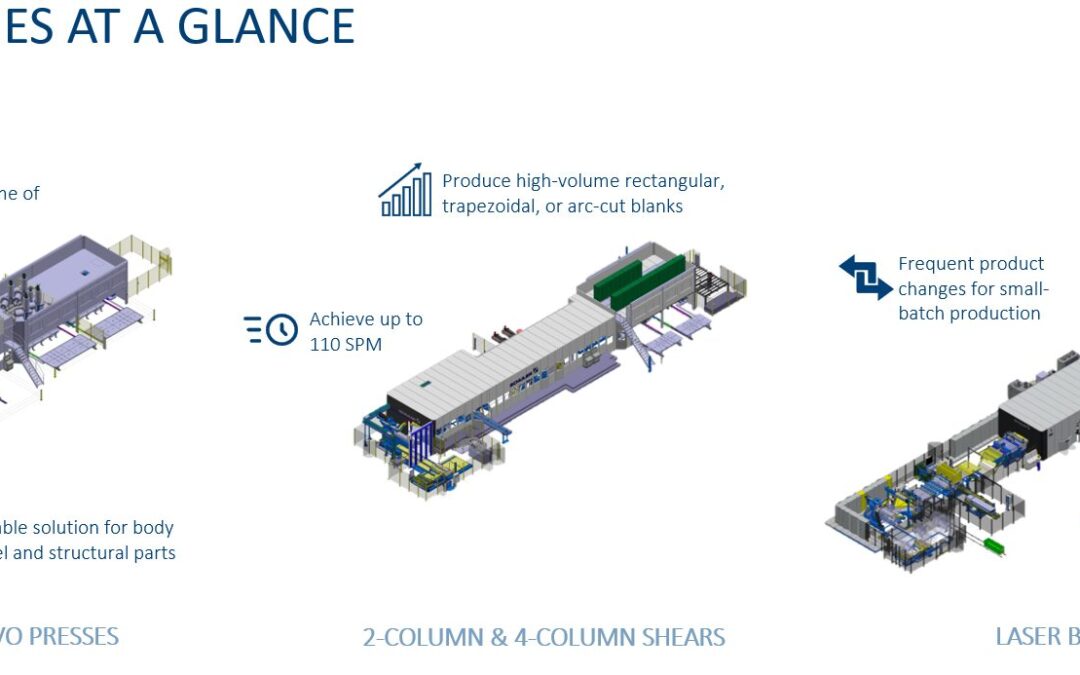
Laser blanking technology addresses market challenges such as frequent die changes, the need to increase capacity, and improving plant floor utilization, material utilization, and downstream processes.
Laser Blanking Eliminates Frequent Die Changes
It is important to remember that there are no dies with laser blanking technology, and no dies means no die changes. Overall Equipment Effectiveness (OEE) of up to 80% can be achieved with laser blanking technology. In fact, 4 to 6 million parts per year of various materials are produced with the help of DFT—including mild steel, high-strength steel, and advanced high strength steel. Even processing press hardening steels with an aluminum-silicon coating is possible with laser blanking. Surface and cutting quality can be maintained over this spectrum of steel grades. Laser blanking technology can even achieve effective small batch production of Class A outer body panels and structural parts typically up to 3mm thick.
Laser Blanking Increases Plant Output
Competitive high-speed and high-output results can be achieved in multiple ways with laser blanking technology. The above-ground coil-fed line, optimized to achieve short setup time, can handle coils with material widths up to 2,150 mm, weighing up to 30 tons. The material transport is smooth and controlled, simplifying setup, and leading to uninterrupted processing within the laser cell.
There are three highly dynamic, and simultaneously moving, laser cutting heads within the laser cell of these lines. These laser cutting heads cut the programmed blank contour from a continuously moving material coil. Cutting speeds can exceed 100 meters per minute. The material is protected against any process contamination throughout the cutting process by the custom-designed cutting clearance and material transport.
The blanks and the offal (scrap) must be separated once the cutting process is complete. This occurs through the use of automated systems specially adapted to the individual products. Following the separation, the blanks are cleaned, before moving into the automatic stacking system. This ensures outstanding body shell quality.
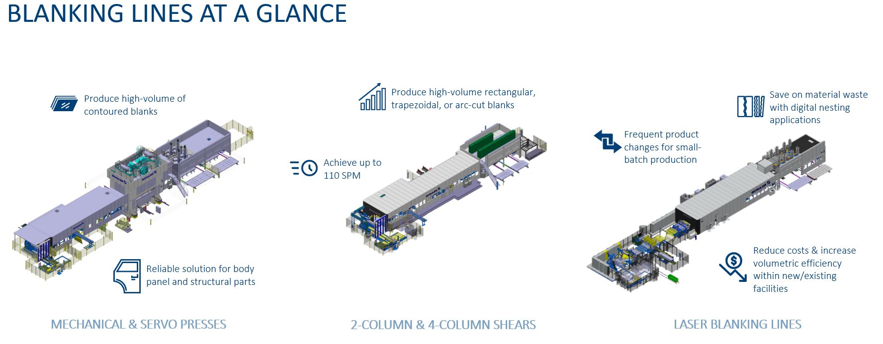
Figure 2 reveals the high-speed and high-output results for outer body parts. Each part is measured by improved output per minute and hour to achieve an OEE of 80%. Significantly, laser blanking lines can achieve up to 45 parts per minute and reduce costs per blank.
Figure 2: High productivity achieved with laser blanking.
Laser Blanking Needs Less Floor Space and Reduces Infrastructure Costs
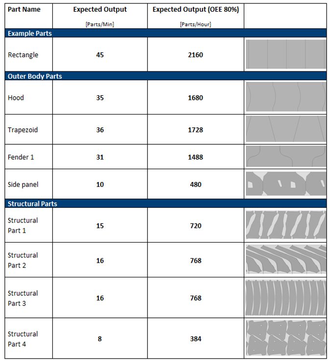
There is a multitude of ways for manufacturers to increase capacity within new or existing facilities when incorporating laser blanking technology into their production process. The clearest example, indicated within the picture below, is that very little floor space is needed in comparison to conventional blanking lines. All the circled areas in Figure 3 can be eliminated when utilizing laser blanking technology.
Figure 3: Circled areas represent freed floor space with laser blanking.
Laser blanking lines are designed to be installed above ground, so they can be used in normal logistics buildings—eliminating the need for special foundations required by press systems.
Capital equipment and operations expenses have drastically increased with supply chain shortages. Laser blanking technology provides cost-effective benefits that can be critical for such challenges.
For new facilities:
No heavy press foundation or loop pits are needed.
There are no noise or vibration emissions.
It is possible to operate next to press lines.
There is very little floor space required.
No special infrastructure is needed for die handling.
For existing facilities:
No heavy press foundations or loop pits are needed, and no special infrastructure is needed for die handling—similar to new facilities.
There are reduced ground and building costs.
Other potential benefits include an optimized tryout process, material cost, and weight savings.
Laser blanking lines require no press foundation, loop or press pits, die cranes, or die storage areas. A crane to handle the coils and a forklift to take the blank stacks where they need to go is all manufacturers need. The building and infrastructure costs of a die-based blanking system normally double the costs for capital equipment investment alone. A laser blanking line eliminates a large portion of these costs.
Laser Blanking Improves Material Utilization
Up to 90% of blank costs are determined by the material price. The most significant leverage would be to reduce scrap and save on materials. Schuler conducted research based on the production of 300,000 cars per year, at 350 kg per car and $1,000 USD per ton of steel to provide a realistic inside look at how much cost savings can be achieved with laser blanking. The result was $1 Million USD saved with just 1% of material savings. This is extremely significant as material costs keep increasing.
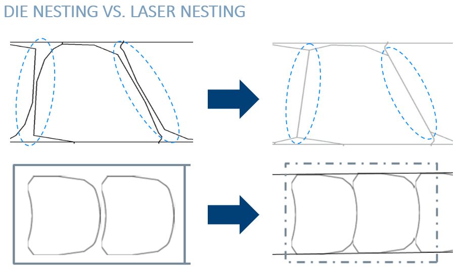
Laser blanking is the digital way to cut blanks. All that’s needed to create a blanking program is a drawing to be loaded and a material to be selected. The part-specific program can be created offline and modified at any time. It is designed to create optimal combinations of material utilization and output—resulting in a high level of flexibility that significantly reduces development time for optimal blanks while also allowing for need-based production. This makes production planning easier, and it also opens the door to continuous contour optimizations for the forming process. Additionally, laser cutting does not require any gaps between individual parts due to smart nesting capabilities that cannot be achieved in comparison to die nesting or flatbed laser nesting. The combined smart, flexible nesting functions unlock new potential for material savings. Manufacturers can optimize individual blanks and eliminate the separating strip or connection bridges. Scrap savings in the forming process can also be achieved as there are no geometric restrictions due to cutting dies, and manufacturers can continuously optimize or adapt parts.
Figure 4 showcases the comparison of die nesting (the two graphics on the left) versus a laser-optimized blank contour and material savings via smart, laser blanking line nesting (the two images on the right).
Figure 4: Die nesting (left) compared with laser-optimized blank contours highlighting potential material savings (right)
Laser blanking technology allows for the conversion of rectangular and trapezoidal blanks into contoured blanks. Blank shapes are no longer restricted to straight lines – programmable laser cutting allows for edges with a sinusoidal or arched contour—improving the material utilization rate or forming characteristics. Adaptations of various geometric shapes can be achieved with optimized nesting of laser blank contours. These images in Figure 4 are just an example, with the possibility of more complex shapes and nesting patterns.
Overall, laser blanking lines can have an equivalent throughput to conventional blanking lines, but laser blanking lines can achieve up to 10% greater material utilization.
Laser Blanking Improves Downstream Processes
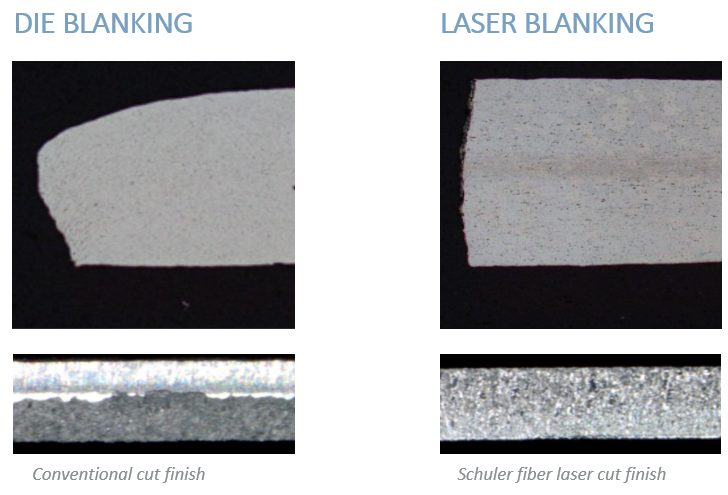
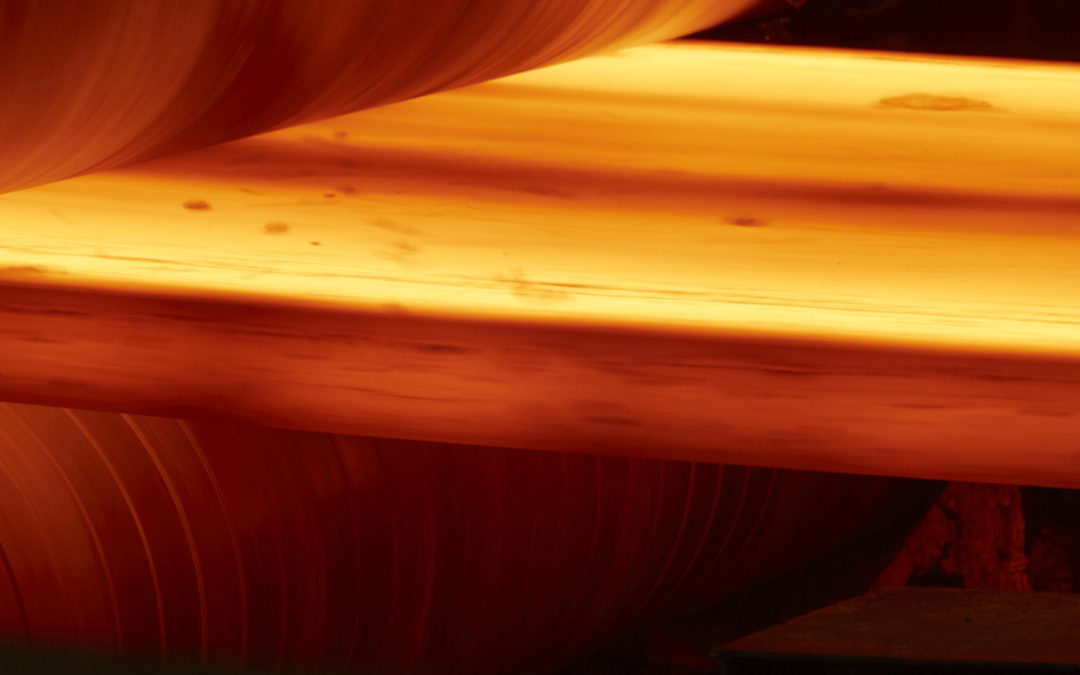
High surface quality can be achieved with laser blanking technology as clean blanks are produced with homogeneous and uniform cutting edges—and no burr cleaning is needed during or after the forming process. There is also a reduction in dripping during the hot forming process—which leads to a dramatically increased lifespan of the hot forming rollers—as the laser melts the dripping layer instead of squeezing it into the cutting edge. Figure 5 provides a comparison of the edges produced via die blanking with a conventional cut finish with that produced by laser blanking with a laser fiber cut finish.
Figure 5: Conventional cut edge condition produced from die blanking (left) and laser fiber cut edge condition produced from laser blanking (right).
Laser blanking lines are much more cost-effective for the production of blanks when manufacturers keep these five benefits in mind. The costs for personnel, logistics, buildings, dies, storage areas, repairs, and other additional costs can add up to a pricey amount. Laser blanking lines are the smart manufacturing choice as this technology yields a higher OEE in comparison to conventional blanking lines through the elimination of die-related downtime and lengthy time changes. The system only stops for a short time when the coil needs to be changed.
Schuler will present laser blanking technology, along with a variety of digital tools that create the “Press Shop of the Future” at FABTECH Chicago 2023 (booth # D41306). Tiago Vasconcellos, Sales Director at Schuler North America, will present “How Smart is Your Press Shop?” during FABTECH’s Educational Conference. The presentation will use The Smart Press Shop, a newly formed joint venture between Porsche and Schuler, as an exemplary case study for smart manufacturing standards. Attendees will discover innovative and practical ways to incorporate digitalization into production and become a state-of-the-art stamping facility directly from Schuler.
Schuler offers customized cutting-edge technology in all areas of forming—from the networked press to press shop planning. In addition to presses, Schuler’s products include automation, dies, process know-how, and service for the entire metalworking industry. Schuler’s Digital Suite brings together solutions for networking forming technology and is continuously being developed to further improve line productivity and availability. Schuler customers include automotive manufacturers and suppliers, as well as companies in the forging, household appliance, and electrical industries. Schuler presses are minting coins for more than 180 countries. Founded in 1839 at the Göppingen, Germany headquarters, Schuler has approximately 5,000 employees at production sites in Europe, China and the Americas, as well as service companies in more than 40 countries. The company is part of the international technology group ANDRITZ.
Schuler’s global portfolio of world-renowned brands include BCN (Bliss Clearing Niagara) Technical Services, Müller Weingarten, Beutler, Umformtechnik Erfurt, SMG Pressen, Hydrap Pressen, Wilkins & Mitchell, Bêché, Spiertz Presses, Farina Presse, Liebergeld, Peltzer & Ehlers, Schleicher, and Sovema Group.
Schuler North America (Schuler), headquartered in Canton, Michigan, is the North American subsidiary of Schuler Group. Schuler provides new equipment, spare parts, and a portfolio of lifecycle services for all press systems—including preventative maintenance, press shop design and optimization, turnkey installations, retrofits for existing systems, and localized production and service. Schuler’s best-in-class position in the metalworking and materials industry serves automotive manufacturers and tier suppliers, as well as home appliance, electronics, forging, and other industries.
Many steel parts on a vehicle require corrosion protection, regardless of whether they are exposed or unexposed applications. The most common way to accomplish corrosion protection is to coat Advanced High-Strength Steels (AHSS) with zinc by means of a couple of different processes. This AHSS Insights Blog goes over the most common.
Electrogalvanizing
Electrogalvanizing is a zinc deposition process, where the zinc is electrolytically bonded to steel in order to protect against corrosion. The process involves electroplating: running an electrical current through the steel strip as it passes through a saline/zinc solution. Electrogalvanizing is done at room temperature, so the microstructure, mechanical, and physical properties of AHSS products achieved on a continuous anneal line (CAL) are essentially unchanged after the electrogalvanizing (EG) process. EG lines have multiple plating cells, with each cell capable of being on or off. As a result, chief advantages of electrogalvanizing compared to hot dipped galvanizing include: (1) lower processing temperatures, (2) precise coating weight control, and (3) brighter, more uniform coatings which are easier to convert to Class A exposed quality painted surfaces.
The majority of electrogalvanizing lines can apply only pure (free) zinc coatings, known as EG for electrogalvanized steel. Selected lines can apply different types of coatings, like EGA (electro-galvanneal) or Zn-Ni (zinc-nickel).
There are no concerns about different alloy phases in the coating as with galvanneal coatings. The lack of aluminum in the coating results in improved weldability. The biggest concern with electrogalvanizing lines is the coefficient of friction. Electrogalvanized (EG) coatings have a relatively high coefficient of friction—higher than hot dipped galvanized coatings, but lower than galvanneal coatings. To improve formability of electrogalvanized sheets, some automakers choose to use a steel mill-applied pre-lube rather than a simple mill-applied rust preventive oil.
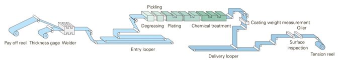
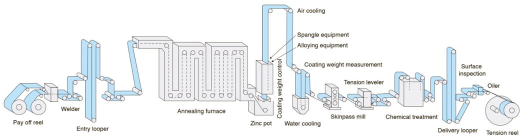
A representative EG line is shown in Figure 1. Different EG lines may use different technologies to apply the zinc crystals. Because the zinc crystals are deposited in a different fashion, these different processes may potentially result in different surface morphology and, in turn, a different coefficient of friction.
Figure 1: Schematic of an electrogalvanizing line.
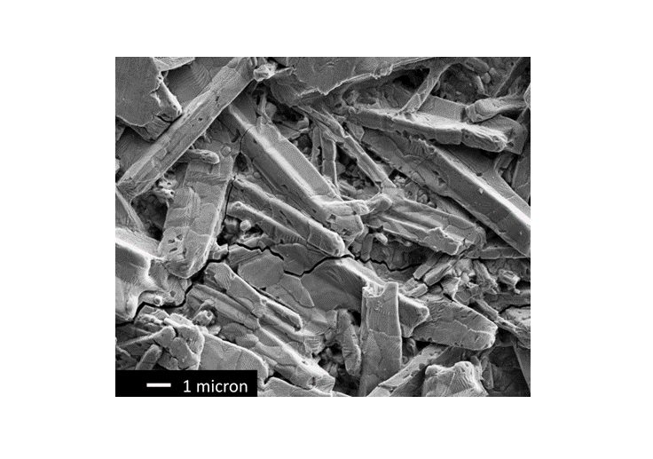
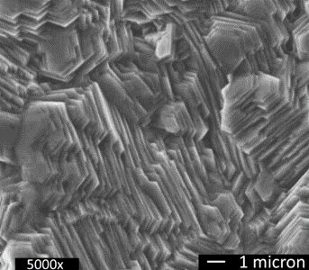
A higher coefficient of friction may be found under dry conditions, but the “stacked plate-like surface morphology” (Figure 2) allows these coatings to trap and hold lubrication better than the smoother surfaces of hot dipped galvanizing coatings. Auto manufacturers should therefore consult the steel supplier for specific lubricant recommendations based on the forming needs.
Figure 2: High magnification photograph of electrogalvanized steel surface showing stacked plate-like structure.
Hot Dip Galvanize and Hot Dip Galvanneal
Hot dipped galvanizing – applying a zinc coating over the steel – is the most common way to achieve corrosion protection. It is an economical solution, since cold rolled steel can be annealed and coated in the same continuous operation.
A typical in-line continuous hot dip galvanizing line such as that shown in Figure 3 uses a full-hard cold rolled steel coil as the feedstock. Individual coils are welded together to produce a continuous strip. After cleaning, the strip is processed in a continuous annealing furnace where the microstructure is recrystallized, improving forming characteristics. The annealing temperature is adjusted to produce the desired microstructure associated with the ordered grade. Rather than cooling to room temperature, the in-process coil is cooled to just above 460°C (860°F), the temperature of the molten zinc bath it enters. The chemistry in the zinc pot is a function of whether a hot dipped galvanized or galvannealed coating is ordered. Hot rolled steels also are coated with the hot dip galvanizing process, but different processing conditions are used to achieve the targeted properties.
Figure 3: Schematic of a typical hot dipped galvanizing line with galvanneal capability.
There are several types of hot dipped coatings for automotive applications, with unique characteristics that affect their corrosion protection, lubricity for forming, weldability and paintability. One of the primary hot dipped galvanized coatings is a pure zinc coating (abbreviated as GI), sometime referred to as free zinc. The molten zinc bath has small amounts of aluminum which helps to form a thin Fe2Al5 layer at the zinc-steel interface. This thin barrier layer prevents zinc from diffusing into the base steel, which leaves the coating as essentially pure zinc.
Coil pass through the molten zinc at speeds up to 3 meters per second. Zinc coating weight is controlled by gas knives (typically air or nitrogen) blowing off excess liquid zinc as the coil emerges from the bath. Zinc remaining on the surface solidifies into crystals called spangle. Molten zinc chemistry and cooling practices used at the galvanizing line control spangle size. Since spangle can show through on a painted surface, a minimum-spangle or no-spangle option is appropriate for surface-critical applications.
The other primary hot dipped coating used for corrosion protection is hot dipped galvanneal (abbreviated as GA). Applying this coating to a steel coil involves the same steps as creating a free zinc hot dipped coated steel, but after exiting the zinc pot, the steel strip passes through a galvannealing furnace where the zinc coating is reheated while still molten.
The molten zinc bath used to produce a GA coating has a lower aluminum content than what is used to produce a GI coating. Without aluminum to create the barrier layer, the zinc coating and the base steel inter-diffuse freely, creating an iron-zinc alloy with typical average iron content in the 8-12% range. The iron content improves weldability, which is a key attribute of the galvanneal coatings.
The iron content will be unevenly distributed throughout the coating, ranging from 5% at the surface (where the sheet metal coating contacts the tool surface during forming) to as much as 25% iron content at the steel/coating interface. The amount of iron at the surface and distribution within the coating is a function of galvannealing parameters and practices – primarily the bath composition and time spent at the galvannealing temperature. Coating iron content impacts coating hardness, which affects the interaction with the sheet forming lubricant and tools, and results in changes in friction. The hard GA coatings have a greater powdering tendency during contact with tooling surfaces, especially during movement through draw beads. Powdering is minimized by using thinner coatings – where 50 g/m2 to 60 g/m2 (50G to 60G) is a typical EG and GI coating weight, GA coatings are more commonly between 30 g/m2 to 45 g/m2 (30A to 45A).
Figure 4: High magnification photograph of a galvannealed steel surface. The surface structure results in excellent paint adhesion.
Options to improve formability on parts made from GA coated steels include use of press-applied lubricants or products that can be applied at the steel mill after galvanizing, like roll-coated phosphate, which have the additional benefit of added lubricity. The surface morphology of a galvannealed surface (Figure 4) promotes good phosphate adherence, which in turn is favorable for paintability.
Galvannealed coatings provide excellent corrosion protection to the underlying steel, as do GI and EG coatings. GI and EG coatings are essentially pure zinc. Zinc acts as a sacrificial anode if either coating is damaged from scratches or impact, and therefore will corrode first before the underlying steel. The corrosion product of GI and EG is white and is a combination of zinc carbonate and zinc hydroxide. A similar mechanism protects GA coated steels, but the presence of iron in the coating may result in a reddish tinge to the corrosion product. This should not be interpreted as an indication of corrosion of the steel substrate.
Producing galvanized and galvannealed AHSS is challenging due to the interactions of the necessary thermal cycles at each step. As an example, the targeted microstructure of Dual Phase steels can be achieved by varying the temperature and time the steel strip passes through the zinc bath and can be adjusted to achieve the targeted strength level. However, not all AHSS can attain their microstructure with the thermal profile of a conventional hot dipped galvanizing line with limited rapid quenching capabilities. In addition, many AHSS grades have chemistries that lead to increased surface oxides, preventing good zinc adhesion to the surface. These grades must be produced on a stand-alone Continuous Annealing Line, or CAL, without an in-line zinc pot. Continuous Annealing Lines feature a furnace with variable and rapid quenching operations that enable the thermal processing required to achieve very high-strength levels. If corrosion protection is required, these steel grades are coated on an electrogalvanizing line (EG) in a separate operation, after being processed on a CAL line.
Hot dipped galvanizing lines at different steel companies have similar processes that result in similar surfaces with respect to coefficient of friction. Surface finish and texture (and resultant frictional characteristics) are primarily due to work roll textures, based on the customer specification. Converting from one coating line to another using the same specification is usually not of major significance with respect to coefficient of friction. A more significant change in friction is observed with changes between GI and GA and EG.
In this edition of AHSS Insights, George Coates and Menachem Kimchi get back to basics with important fundamentals in forming and joining AHSS.
As the global steel industry continues its development of Advanced High-Strength Steels (AHSS), including 3rd Gen products with enhanced formability, we’re reminded that successful application is still dependent on the fundamentals, both in forming and joining. In this blog article, we address some of those forming considerations, as well as highlighting common joining issues in manufacturing.
Forming Considerations
The somewhat lower formability of AHSS compared to mild steels can almost always be compensated for by modifying the design of the component and optimizing blank shape and the forming process.
In stamping plants, we’ve observed inconsistent practices in die set-up and maintenance, surface treatments and lubrication application. Some of these inconsistencies can be addressed through education, via training programs on AHSS Application Guidelines. These Guidelines share best practices and lessons learned to inform new users on different behaviors of specific AHSS products, and the necessary modifications to assist their application success. In addition to new practices, we’ve learned that applying process control fundamentals become more critical as one transitions from mild steels to AHSS, because the forming windows are smaller and less forgiving, meaning these processes don’t tolerate variation well. If your present die shop is reflective of housekeeping issues, such as oil and die scrap on the floor or die beds, you are a candidate for a shop floor renovation or you will struggle forming AHSS products.
Each stamping operation combines three main elements to achieve a part meeting its desired functional requirements:
appropriate die materials, including their surface treatment, and
the correct lubricant that maintains its lubricity during the forming operation.
There is good news, in that our industry is responding with new products and services to improve manufacturing performance and save costs.
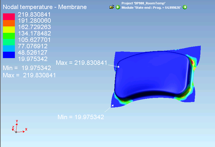
As an example, lubrication application is often overlooked, and old systems may be ineffective. In the forming of AHSS, part temperatures can become excessive, and break down lubricant performance. Figure 1 shows an example of part temperatures from an Ohio State University study conducted with DP 980 steels.O-1
Figure 1: Example Temperature distribution for DP 980 Steel.O-1
Stampers often respond by “flooding” the process with extra lubricant, thinking this will solve their problem. Instead, lubricant viscosity and high temperature stability are the most important considerations in the lubricant selection, and new types exist to meet these challenges. Also, today there are new lubrication controllers that can finely control and disperse wet lubricants evenly across the steel strip, or in very specific locations, if forming requirements are localized. These enable better performance while minimizing lubricant waste (saving cost), a win-win for the pressroom.
Similarly, AHSS places higher demands on tool steels used in forming and cutting operations. In forming applications, galling, adhesive wear and plastic deformation are the most common failure mechanisms. Surface treatments such as PVD, CVD and TD coatings applied to the forming tool are effective at preventing galling. Selection of the tool steel and coating process used for forming AHSS will largely depend on the:
New die materials such as “enhanced D2” are available from many suppliers. These improve the balance between toughness, hardness and wear resistance for longer life. These materials can be thru-hardened, and thus become an excellent base material for PVD or secondary surface treatments necessary in the AHSS processing. And new tool steels have been developed specifically for hot forming applications.
Joining Considerations
In high-volume production different Resistance Spot Welding (RSW) process parameters can be used depending on the application and the specifications applied. Assuming you chose the appropriate welding parameters that allows for a large process window, manufacturing variables may ruin your operation as they strongly effect the RSW weld quality and performance.
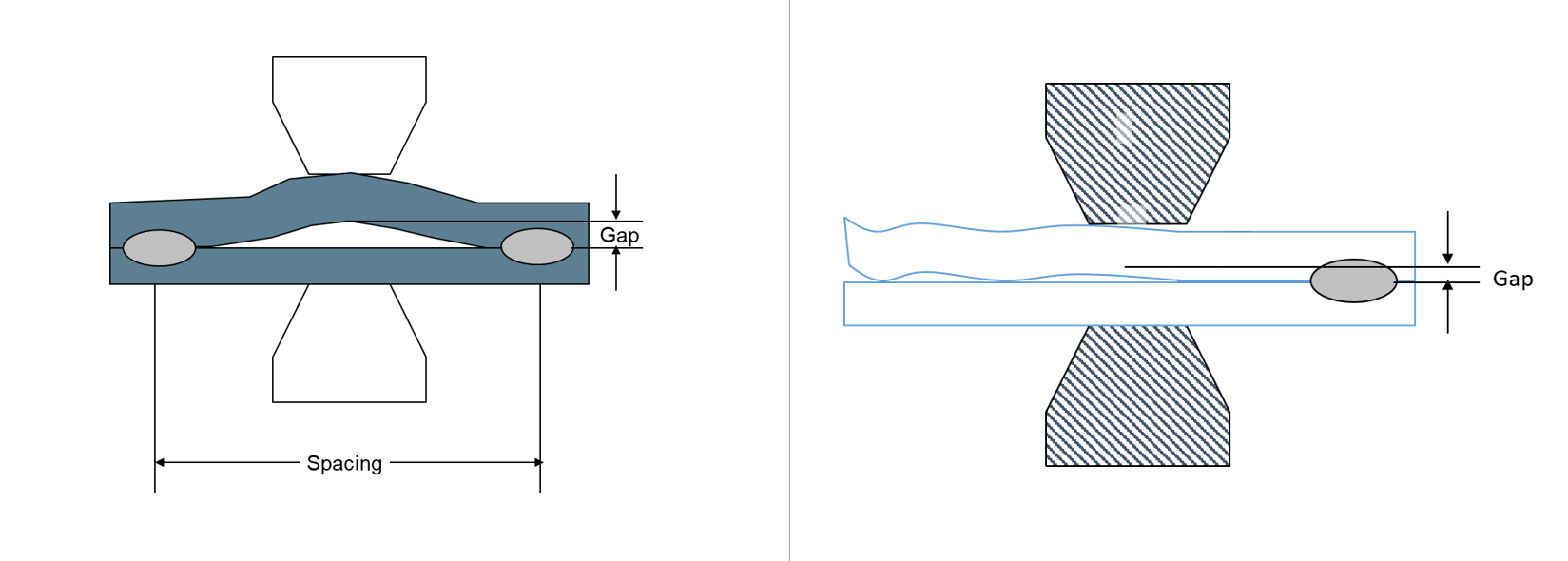
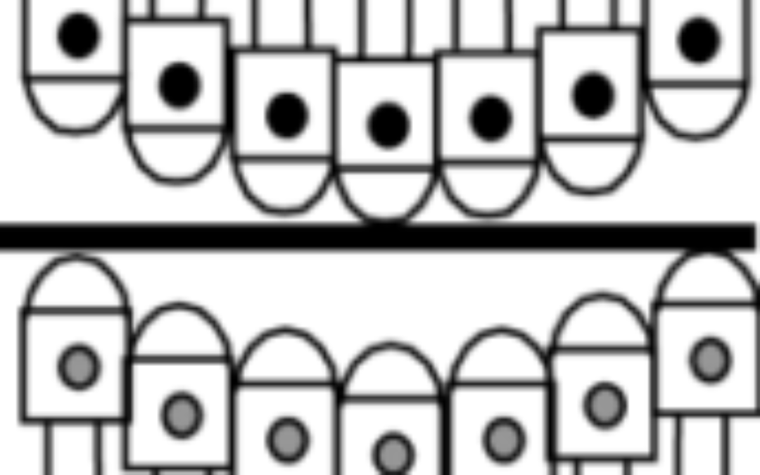
Material fit-up
One of the great advantages of the RSW process is the action of clamping the material together via the electrode force applied during the process. However due to the pre-welding condition/processing such as the stamping operation, this fit-up issue, as shown in Figure 2, can be very significant especially in welding an AHSS product. In this case the effective required force specified during the process setup for the application is significantly reduced and can result in an unacceptable weld, over-heating, and severe metal expulsion. If the steels are coated, higher probability for Liquid Metal Embrittlement (LME) cracking is possible.
Figure 2: Examples of Pre-Welding Condition/Processing Fit-Up Issues.
For welding AHSS, higher forces are generally required as a large part of the force is being used to force the parts together in addition to the force required for welding. Also, welding parameters may be set for pre-heating with lower current pulses or current up-slope to soften the material for easier material forming and to close the gap.
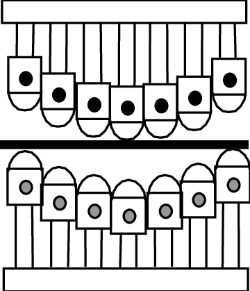
Electrodes Misalignment
During machine set up, the RSW electrodes need to be carefully aligned as shown in Figure 3A. However, in many production applications, electrode misalignment is a common problem.
Electrode misalignment in the configurations shown in Figure 3B may be detrimental to weld quality of any RSW application. Of course, the electrode misalignment shown in this figure is exaggerated but the point is that it happens frequently on manufacturing welding lines.
In these cases, the intendent contact between the electrodes is not achieved and thus the current density and the force density (pressure) required for producing an acceptable weld cannot be achieved. With such conditions, overheating, expulsion, sub-size welds and extensive electrode wear will result. Again, if coated steels are involved, the probability for LME cracking is higher.
Note also that following specifications or recommendations for water cooling the electrode is always important for process stability and extending electrode life.
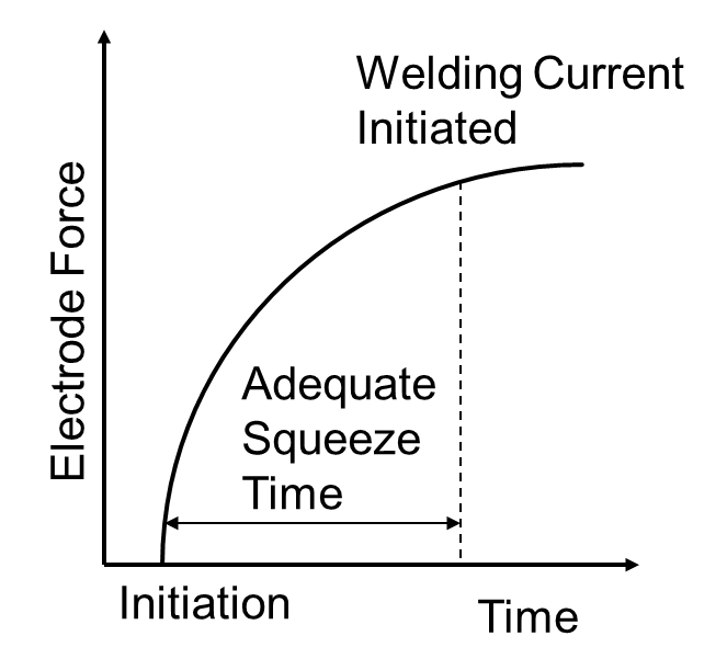
Figure 4: Sequence of Squeeze Time and Welding Current Initiation.
Squeeze Time
The squeeze time is the time required for the force to reach the level needed for the specific application. Welding current should be applied only after reaching this force, as indicated in Figure 4. All RSW controllers enable the easy control of squeeze time, just as with the weld time, for example. In many production operations, a squeeze time is used that is too low due to lack of understanding of its function. If squeeze time is too low, high variability in weld quality in addition to severe expulsion will be the result.
The squeeze time required for an application depends on the machine type and characteristics (not an actual welding parameter such as weld time or welding current for example).
Some of the more modern force gauges have the capability to produce the curve shown in the Figure so adequate squeeze time will be used. If you do not know what the required squeeze time for your machine/application is, it is recommended to use a longer time.
For more on these topics, browse the Forming and Joining menus of these Guidelines.
Thanks is given to Menachem Kimchi, Associate Professor-Practice, Dept of Materials Science, Ohio State University and Technical Editor – Joining, AHSS Application Guidelines, for contributing to this article.
Metallurgy The possibilities of combining iron with other elements and arranging them in novel ways are unparalleled and vast, which is why and how steel keeps reinventing itself from the mild automotive steels of the mid-20th Century to 3rd Generation Advanced...
Forty years ago, the metal forming community needed to figure out how to stamp a new exotic family of steels making inroads into automotive body construction. These grades, called High Strength Low Alloy steels, were much stronger than the commonplace mild steels, and were more formable than the high-strength options available at that time. Initially, only a few steelmakers were able to offer these new grades, but over time more companies added the equipment and know-how necessary to support their customers with these products. Automakers and their supply chain stampers needed to adapt as an increasing number of parts transitioned to HSLA steels.
Fast-forward a few decades, and metal formers are facing similar challenges. Successful forming and joining of Advanced High-Strength Steels is made easier with processes that are tuned to work with the characteristics associated with these alloys. One such technique to improve formability is to employ Active Binder Force Control.
In conventional stamping, a draw ring applies pressure around the binder in order to control the sheet metal flow into the cavity. The ring may be referred to as a binder plate, draw pad, pressure pad, or blank holder. Creating the restraining force typically is done with urethane springs, coil springs, gas springs (like air or nitrogen), or press cushion systems actuated by gas or hydraulic cylinders.
Where the traditional approach applies binder pressure uniformly throughout the press stroke, modern stamping presses can be equipped with cushions having multipoint-control systems (see Figure 1 example). The associated pressure profile can be adjusted around the panel and throughout the stroke to optimize metal flow, prevent splits and wrinkles, and minimize thinning.
Figure 1. An Example of Multi-Point Press Forming Method.P-31
Incorporating Active Binder Control capabilities has several benefits for the press shop, panel quality, and product design, including:
A segmented blankholder combined with individually programmable hydraulic cylinders, sometimes called a flexible binder, allows for precise control of one segment independent of the others.
Pulsating blank holder force has been shown to reduce press tonnage requirements and increase metal flow, with the frequency and amplitude being key variables that must be adjusted based on the grade and thickness of interest.
Pre-acceleration of the cushion reduces shock loading, which minimizes the press-damaging snap-through loads associated with reverse tonnage.
The merits of a variable blank holder force on AHSS springback were documented in a 2004 conference paper.M-63 With the traditional constant binder force approach, springback in the form of side-wall curl was seen in parts made from either a DP590 grade or a mild steel grade used as a control. Increasing the constant binder force helped to reduce springback in the mild steel part.
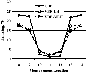
In Figure 2, CBF reflects tests conducted with constant binder force. VBF-LH and VBF-MLH reflect variable binder force tests conducted with a low-high force profile sequence and a medium-low-high force profile, respectively.
Figure 2: Variable Binder Force Reduces Springback.M-63
By employing a variable binder force, springback of both the mild steel and the DP 590 material was substantially reduced. Employing either variable binder force approach reduced the thinning from forming the DP 590 material, resulting in a more uniform strain distribution across the entire channel profile (Figure 3).
Figure 3: Uniform Strain Distribution Achieved with Variable Binder Force.M-63
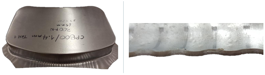
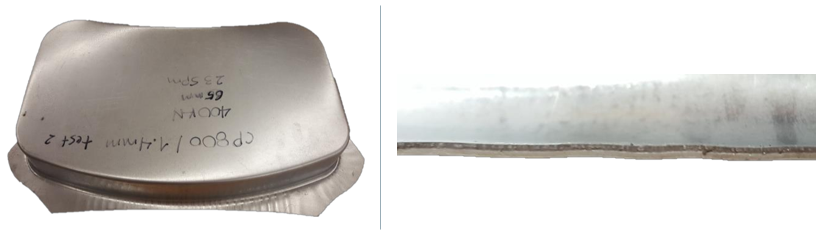
More recently, a presentation from 2018 showed CP 800 panel quality improvements associated with variable blank holder force capabilities.D-33 Panel results from a constant binder force of 300 kN and 400 kN are shown in Figures 4 and 5, respectively. Both exhibit severe wrinkling in the flange. Applying 500 kN binder force was not feasible due to exceeding the press tonnage curve limits throughout the stroke.
Figure 4: CP800 Panel Formed with Constant Binder Force of 300 kN, and Associated Close-Up of Flange.D-33
Figure 5: CP800 Panel Formed with Constant Binder Force of 400 kN, and Associated Close-Up of Flange.D-33
Figure 6 shows the panel produced with a variable binder force. The chosen profile fit within the press tonnage requirements and minimized wrinkles.
Figure 6: CP800 Panel Formed with Variable Binder Force Ramping from 300 kN to 600 kN, and Associated Close-Up of Flange.D-33
Active drawbead control is an offshoot of these techniques, allowing for the magnitude and timing of drawbead engagement to be optimized for the requirements of each part. A description of using stake beads to minimize springback is available in the Springback article – active drawbead control is one approach to actuate beads.
The initial laboratory studies relating to active binder force control go back nearly 20 years ago. In the coming years, more information will enter the public domain on how metal formers are using these concepts in production. When you look to purchase a servo press, be sure to ask your press manufacturer about programmable cushions.