Joining Dissimilar Materials, Resistance Welding Steel to Aluminium
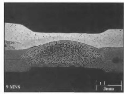
In order to reduce the thickness of brittle intermetallic compound (IMC) formed at Aluminium/Steel interface to improve the mechanical properties of resistance spot welding of Aluminium/Steel, different interlayers, such as Al-cladded steelS-16, O-3, Y-4, Al-Si alloyW-15, Al-Mg alloyI-6, pure Al W-16, Zn coating.M-10, U-4, A-21 Sun et al.S-16 has done resistance spot welding of 1.4-mm SAE 1008 mild steel with 2-mm 5182-O aluminium alloy using 1 mm/1.5 mm cold rolled aluminium-clad steel as a transition metal with Aluminium/Steel thickness ratio of 20/80 (thickness ratio was not optimized). The formation of IMC cannot be observed at the interface for cold rolled aluminium-clad steel. The electrodes used were Class 2 30-deg truncated cone with 8-mm surface diameter and 3-inch face radius on the aluminium side and 30-deg truncated cone with 8-mm flat surface diameter on the steel side. Two separate nuggets created the aluminium and steel sides with a final nugget diameters of 10.1 mm and 8.2 mm, on aluminium and steel sides respectively, at the end of the 3rd pulse (Figure 1). With increasing welding time from 1 pulse to 3 pulses, the intermetallic compound layer thickness increased from 0 µm to 8.5 µm. As a comparison, the IMC layer thickness was approximately 65 µm for resistance spot welding of 1-mm AA 5052 and 0.8-mm low carbon steel without transition metal. The static and dynamic strength of the RSW samples in cross-tension and coach peel test were comparable to those of the peak load of self-piercing rivets (SPR). However, lap shear tensile testing of RSW samples had lower energy absorption than dissimilar SPR samples due to different failure modes (interfacial fracture may occur). Fatigue strength of RSW samples were lower than those of SPR samples due to stress concentration and tensile residual stress at the notch tip.
Figure 1: Cross-sectional macrostructure of resistance spot welding of SAE1008/A5182-O with 3 pulses of 12 cycles and welding current of 13.6 kA.S-16
Oikawa et al.O-3 have done resistance spot welding of 0.4 mm-thick cold rolled steel with 0.6 mm-thick pure aluminium with 0.77 mm-thick aluminium-clad steel sheet as the insert metal. Fe-Al IMCs have not been noted at the Aluminium/Steel interface of aluminium-clad steel sheet and a peel strength of 32.1 N/mm can be achieved. IMC layer thickness was about 5 µm at Al/steel interface when aluminium alloy and steel was resistance spot welded with aluminium clad steel sheet as insert. However, the tensile shear strength (Figure 2) and U-tension strength (Figure 3) can be 3.6 kN and 1.5 kN which were similar to Al/Al resistance spot weld joint and were much higher than direct resistance spot welding of 2.4 kN and 0.6 kN. However, it should be noted that resistance spot welding with aluminium-clad steel added weight, and difficulties in hot rolled aluminium cladding process result in high cost. Thus, more investigations have been done recently on improving the cladding method and using thinner and lighter metals as interlayers.
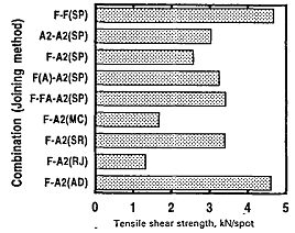
Figure 2: Comparison of tensile shear strength of Al/steel joints by various methods (SP-spot welding; MC-mechanical clinching; RJ-rivet joining; AD-adhesion bonding).O-3
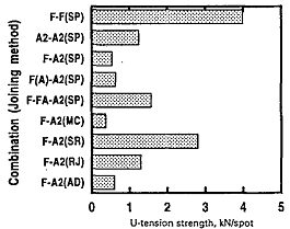
Figure 3: Comparison of U-tension strength of Al/steel joints by various methods (SP-spot welding; MC-mechanical clinching; RJ-rivet joining; AD-adhesion bonding).O-3
In order to reduce the IMC layer thickness, Zhang et al.W-15 used 4047 AlSi12 as an interlayer to suppress the IMC growth during resistance spot welding of 1 mm H22YD-Z100 Zn-coated high-strength steel sheets with 1.5 mm EN AW 6008-T66 aluminium alloy sheets. The effect of different interlayer thickness, i.e. 100 µm, 200 µm, 300 µm, 400 µm, on IMC growth behavior and mechanical properties were investigated. IMCs consisted of Fe2(Al,Si)5 and Fe4(Al,Si)13 and the thickness of IMCs reduced from 1.8 µm to 0.6 µm as the thickness of AlSi12 interlayer, increasing from 100 µm to 400 µm. But all were much thinner compared to 4 µm for spot welds without an interlayer. Nugget diameter reduced with increasing interlayer thickness and maximum tensile shear strength of 6.2 kN and pull-out failure mode were obtained with an interlayer thickness of 300 µm.
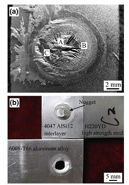
Figure 4: Fracture modes of H220YD high-strength steel/6008-T66 resistance spot weld joints (a) interfacial fracture without interlayer and (b) pull-out failure with 4047 AlSi12 interlayer thickness of 300 µm. W-15
Ibrahim et al.I-6 had investigated resistance spot welding of 2 mm A6061-T6 and 2 mm type 304 austenitic stainless steel with 80 µm thick Al-Mg alloy (80 wt % Al and 20 wt% Mg). Under the same welding condition, lap shear tensile strength was higher for welds with an Al-Mg interlayer than without the interlayer, and a peak strength of 8.4 kN can be obtained with welding current of 16.1 kA and welding force of 9.3 kN. A thin IMC layer of approximately 2 µm can be observed, which lead to a high strength. Fatigue strength of dissimilar RSW Aluminium/Steel samples were higher than Friction Stir Spot Welding samples. The failure mode depended on the load level. Pull-out failure occurred at high load (Pmax > 3 kN), shear fracture at 2.25 kN < Pmax <3 kN, upper Al sheet fracture at Pmax < 2.25 kN.
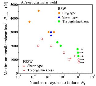
Figure 5: Relationship between peak load and number of cycles.I-6
Galvanized steel (GI) and Galvannealed steel (GA) are widely used in the automotive industry, and the presence of Zn layer may affect the weldability of Aluminium/Steel. Al-Zn eutectic liquid formed at Aluminium/Steel interface can efficiently remove oxide film and squeezed outside by electrode force. Thus, metallic surface of aluminium and steel can be revealed, and the Al-Fe IMC layer formed and a metallurgical bond was created.M-10, U-4 Arghavani et al.A-21 have investigated the resistance spot welding of 2 mm Al-5052 to 1 mm low carbon galvanized steel (ASTM A653 CS Type B-G60) (GI/Al) and compared that with the weldability of Al 5052 to uncoated steel DC01 (PS/Al). It showed the IMC layer at the GS/Al interface with the tongue-like layer of Fe2Al5 on the steel side and needle-like FeAl3 on the aluminium alloy side, as normally observed in Aluminium/Steel dissimilar welding (Figure 6).Z-3, U-4 GI/Al joints had thinner IMC layers at almost all the welding currents compared to PS/Al joints. And the IMC layer thickness in GI/Al increased initially with increasing welding current up to 12 kA and then decreased beyond it, which was due to heat consumption with Zn evaporation at higher welding current (I > 12 kA). Tensile shear strength of GI/Al welds were lower than PS/Al welds at welding current less than 12 kA since lower current led to incomplete nugget at GI/Al welds. However, tensile shear strength of GI/Al welds exceeded PS/Al welds at higher welding current since IMC layer thickness was over the critical value of approximately 5.5 µm for PS/Al joints at the higher welding current (Figure 7). Both GI/Al and PS/Al had an interfacial fracture mode with crack initiation at the peripheral regions of the weld and propagated through the IMCs layer/aluminium sheet.
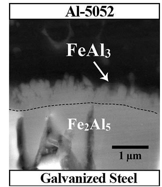
Figure 6: SEM image of IMC layer in GS/Al specimen.A-21
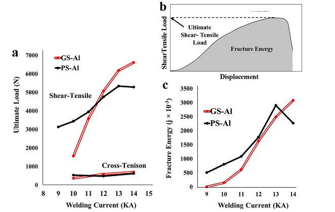
Figure 7: (a) Ultimate tensile shear and cross-tension strength vs welding current; (b) schematics of load-displacement curve and fracture energy calculation for tensile shear testing; (c) Fracture energy vs welding current.A-21
Joining Dissimilar Materials
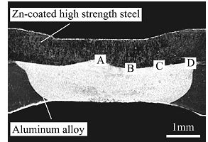
Figure 1 shows a typical cross-section of a resistance spot weld (RSW) joint of 1 mm-thick H220 Zn-coated High-Strength Steel and 1.5 mm-thick 6008-T66 aluminium alloy. Based on resistance spot welding process simulation by ANSYS, the Al/Steel interface temperature is 1120 oC with welding current of 9 kA and welding time of 300 ms. The high interfacial temperature at the Al/Steel interface melts Al alloys and liquid Al alloy wet and spread on the solid steel surface which creates a special brazed joint.
Figure 1: Cross-sectional macrostructure of typical Al/Steel resistance spot welds.Z-4
The interaction of liquid Al alloy with solid steel results in the formation of Fe-Al intermetallics (IMCs), which are mainly composed of lath-like/tongue-like shaped η-Fe2Al5 on steel side and coarse/fine needle-like shaped θ-FeAl3/Fe4Al13 on Al alloy side. For the morphology shown in Figure 2, IMCs have higher hardness compared to the Al or steel base metal, with average hardness of approximately 8.7 and 6.5 GPa for Fe2Al5 and Fe4Al13 respectively, while the average hardness of Al and steel near to the interface were 1.1 and 2.1 GPa respectively.Z-2 The distribution of IMCs at the Al/steel interface is non-uniform, with the thickest IMCs at the center of the weld and a reduced IMCs thickness observed approaching the weld periphery.
The formation and growth of IMCs at the Al/Steel interface are mainly affected by the temperature at the Al/Steel interface and reactive diffusion time. With constant welding current of 9 kA, the thickness of the IMCs increase from 2.9 µm to 13 µm as welding time increases from 100 ms to 300 ms. With constant welding time of 250 ms, a rapid increase of the IMCs from 1.5 to 5.6 µm is observed as welding current increases from 5 to 9 kA. Thus, with increasing welding time and/or welding current, IMCs thickness increase due to the higher interfacial temperature and longer reaction time of liquid Al alloy with solid steel. Resistance spot welding of A6008 andH220 Zn-coated High-Strength Steel can achieve a peak strength of 3.3 kN at welding current of 9 kN and welding time of 250 ms with interfacial fracture at the Al/steel interface, since the crack initiates at the brittle IMC compound layer (Fe2Al5) and tends to propagate along the IMC layer.Z-3
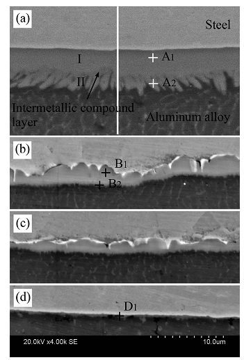
Figure 2: SEM images of Al/Steel interface regions in previous figure. (a)-(d) corresponds to region A-D respectively.Z-4
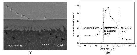
Figure 3: Nanoindentation across H22YD GI high strength steel/A6008-T66 resistance spot weld: (a) Nanoindents; (b) Nanohardness profile.Z-4
The nugget diameter, IMC compound layer thickness and mechanical properties of Al/steel weld joints can be affected by electrode morphology. For resistance spot welding of A6008-T66 and H22YD galvanized High- Strength Steel, the optimized electrodes were a planar circular electrode with a surface diameter of 10 mm on steel side and a spherical tip with a spherical diameter of 70 mm on Al side.Z-4 Compared to the conventional F type electrode used in the reference studyZ-3, a flat Al/steel interface can be obtained with larger nugget diameter and less welding defects, including shrinkage void and cracks, as shown in Figure 4. A maximum nugget size of 10 mm can be obtained with the optimized electrode morphology with a reduced intermetallic compound thickness of 4 µm (Figure 5). A peak tensile shear strength of 5.4 kN can be achieved with a nugget pull-out failure mode (Figure 6).
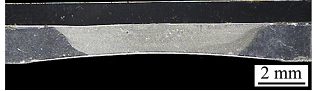
Figure 4: Cross-sectional macrostructure of resistance spot weld Al/steel joint with an electrode spherical diameter of 100 mm on Al alloy side.Z-4
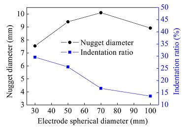
Figure 5: Effects of electrode spherical diameter on nugget diameter and indentation ratio of resistance spot weld joints.Z-4
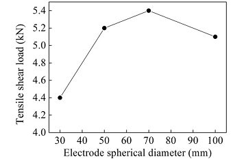
Figure 6: Effects of electrode spherical diameter on tensile shear load of resistance spot weld joints.Z-4
Sigler et al., from General Motors, have shown considerable improvement in the Al/Steel RSW joints that includes multi step direct RSW welding and multi ring, domed-shaped electrodes.S-15, W-14 Welds were carried out using a medium frequency direct current (MFDC) RSW machine via two current pulses, i.e. pre heat pulse of 5 kA and main pulse of 13 kA, 14 kA and 15 kA at various times. Their methodology has shown an importance in the IMC layer thickness and aluminium nugget. Figure 7(a) shows the cross sections of the welds made at the various parameters. More indentation and larger Al nugget diameter are seen at higher times. Figure 7(b) shows that the hardness mapping and the softened region on the both sides of the nugget is observed due to excessive recrystallization. Figure 7(c) shows that the greater the aluminium nugget diameter in the center, the less is the aluminium thickness in the center. Also the IMC layer, as shown in Figure 12(d) increases with the longer weld times. Overall, it was found that the larger aluminium nugget diameter and thicker IMC layer is detrimental for Al/Steel joint integrity.
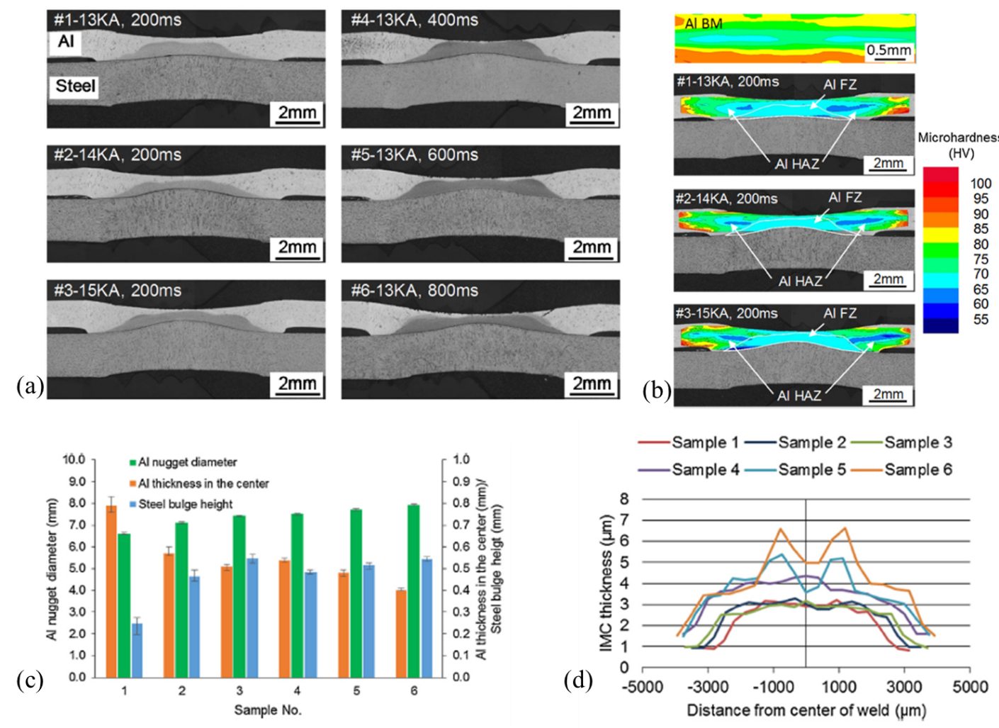
Figure 7: (a). Cross section micrographs of Al/steel RSWs generated by different welding schedules. ,(b) Microhardness contours of Al BM and Al sheets of Al/steel welds. ,(c) Comparison of Al/steel weld dimensions. & (d) Comparison between lap shear stress and average IMC thickness.S-15
Figure 8 shows the relationship between the IMC layer thickness and peak load failure. At 13 kA, 14 kA and 15 kA as indicated by Sample 1, Sample 2 and Sample 3, respectively, in Figure 8(a). Moreover, it is reported that the thinner IMC layer (<3 µm) resulted in bottom pullout failure. Figure 8(b) shows the governing parameters for interfacial or nugget pull out failure.
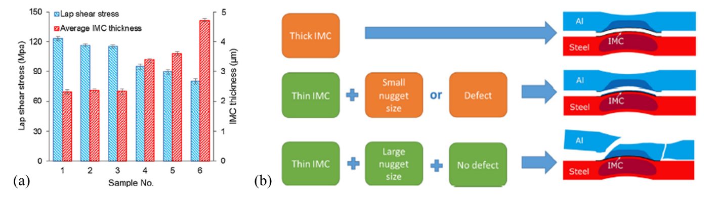
Figure 8: (a) Relationship between peak strength and IMC layer, (b) Model depicting the governing failure mode.S-15
Joining Dissimilar Materials, Resistance Welding Steel to Aluminium
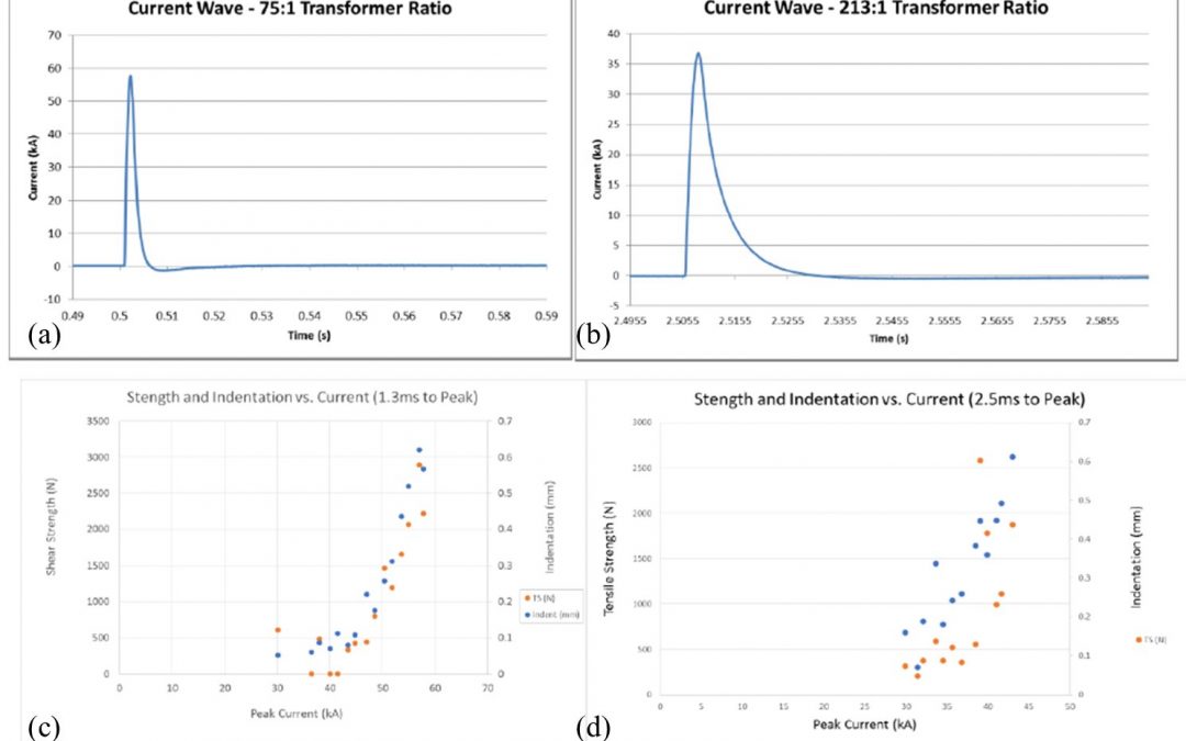
Capacitive Discharge Welding (CDW) is a similar process to RSW except large amount of energy is released in relatively a short amount of time. A research group at The Ohio State University working under supervision of Dr. Menachem Kimchi and Jerry Gould from EWI has investigated the feasibility of Al/Steel joining via this process. Figure 1 shows the current waveforms at 1.3ms & 2.5 and their mechanical strength results.
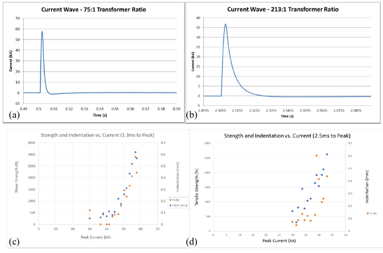
Figure 1: (a) Current waveform for 1.3ms to reach peak value, (b) Current waveform at for 2.5ms to reach peak value (c-d) Lap shear tensile strength and indentation as a function of current and time to reach peak current.
A shorter amount of time can significantly suppress the growth of the intermetallics. The group reported that higher amount of current in short duration of time could result in stronger welds. Figure 15 shows the effect of time on the growth of intermetallic (IMC) and solidification pattern. At 1.3 ms IMC layer thickness is less than 3 microns whereas at 2.5 ms the IMC layer thickness was reported greater than 3 microns. If IMC layer is less than 3 microns it results in nugget pull out failure mode whereas IMC layer of 3 microns or greater mostly result on interfacial failure.P-10
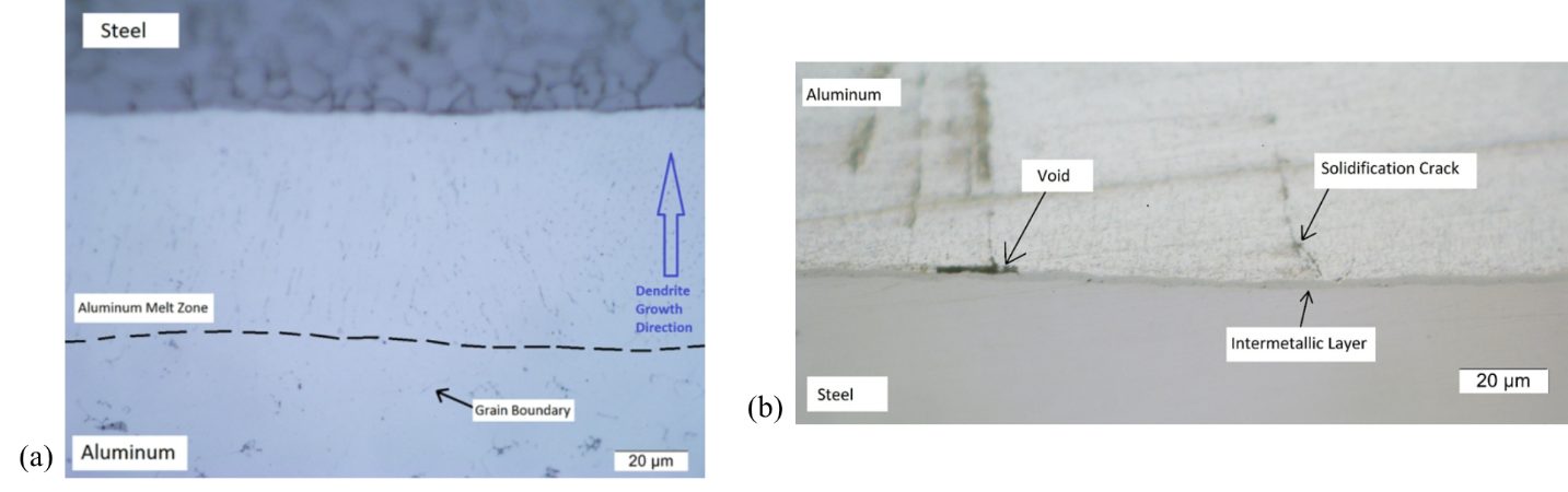
Figure 2: Effect of the ramp up time on the intermetallic layer thickness (a) 2.5ms & (b) 1.3ms.
Joining Dissimilar Materials, Resistance Welding Steel to Aluminium
Among various dissimilar material combinations, Al-steel is one of the most desirable combination. This section will address the number of fundamental issues faced during al-steel joining. Later section will discuss the current approaches to overcome these issues.
Strong and adherent aluminium surface oxide layer needs to be removed for a sound joint between aluminium and steel. The presence of this oxide layer creates uncertainty in the Resistance Spot Welding (RSW) process and deteriorates the electrodes, hence decreasing electrode life. Moreover, it creates wettability issues between steel and aluminium which is an essential for joint formation. Joint is established once surface oxide layer is broken.
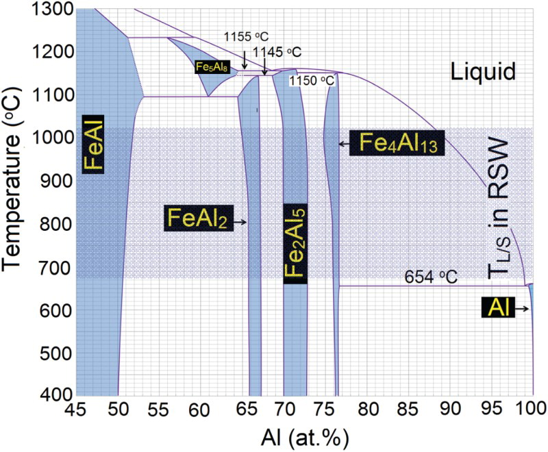
Formation of intermetallic compounds are unavoidable during Al-steel RSW joints. Figure 1 shows the phase diagram between aluminium and iron and from the phase diagram various intermetallics compounds are formed during the RSW process. Formed intermetallics could be iron rich or aluminium rich. Aluminium rich intermetallics are undesirable due to higher hardness compared to iron rich intermetallics. These intermetallics act as stress concentrators, increases the brittleness and making the Al-steel joints more susceptible to cracking.
Figure 1. Al-Fe phase diagramL-8
Another issue is to attain heat balance between aluminium and steel. Compared to steel, aluminium has more electrical & thermal conductivity, and lower bulk resistivity, usually requiring higher amount of current. A large variation in the melting temperature of the aluminium and steel make the RSW process more complicated. Moreover, the thermal conductivity of aluminium is much higher than steel, and a consequent thermal gradient exists and could result in an isolated nugget formation in steel. These factors make the selection of RSW process parameters more challenging.
Excessive electrode indentation in aluminium is another issue that determines the stress state of the joint during loading. It decreases the resistance to necking and decreases the peak load to failure.
Other defects include formation of voids and porosities due to shrinkage, vaporization, expulsion and lack of wetting. Other section in this menu will discuss the basic to advanced, updated approach utilized to improve the joint formation process between aluminium and steel.
Citations
Citation:
W-13. N. T. Williams and J. D. Parker, “Review of resistance spot welding of steel sheets: Part 1 – Modelling and control of weld nugget formation,” International Materials Reviews, vol. 49, no. 2. Taylor & Francis, pp. 45–75, April 2004, doi.org/10.1179/095066004225010523.
.
