The challenges to spot welding of aluminum compared to steel include a tenacious and rapidly forming oxide layer of variable thickness and composition, high electrical and thermal conductivities, small increases in resistivity with temperature, a narrow plastic range, low melting temperatures, and a high coefficient of thermal expansion. Used by permission from Menachem Kimchi,Assistant Professor-Clinical, Materials Science Engineering, Ohio State University, this excerpt from a new book by Kimchi and David Philips, Resistance Spot Welding Fundamentals and Applications for the Automotive Industry, explains these differences for those who wish a deeper understanding. This article is the first of a series by Kimchi on welding of Advanced High-Strength Steels, so stay tuned!
Thermal Conductivity and Electrical Resistivity
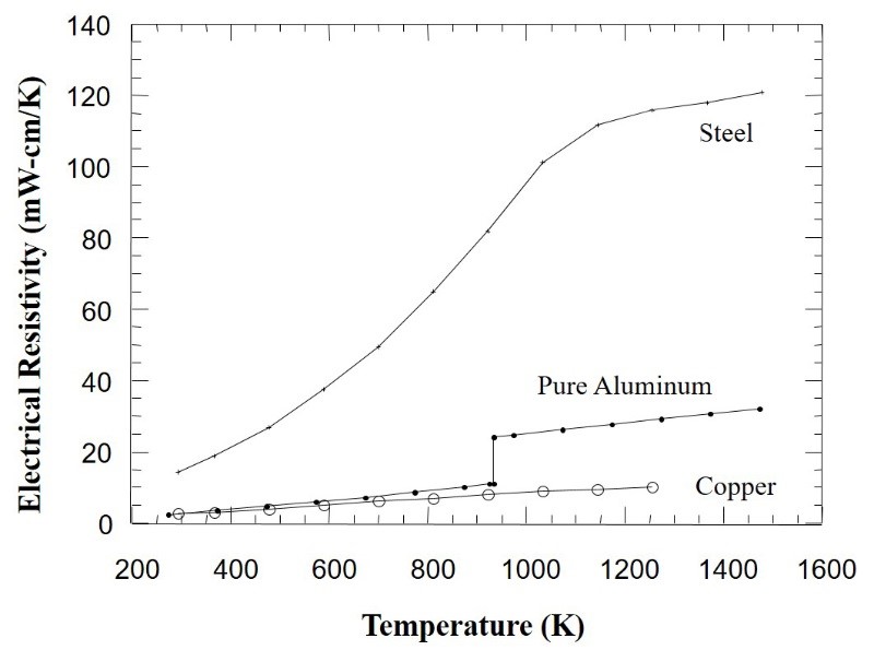
Figure 1: Electrical Resistivity of Steel and Aluminium
(compared to copper electrodes)
The Resistance Spot Welding process, one of the primary processes used in the automotive industry, works best with metal alloys such as steels that have electrical and thermal conductivities that are much lower than the copper-based electrodes used to weld them. Low electrical conductivity (or high resistivity) provides for easy I2R heating, and low thermal conductivity means heat will be extracted from the weld nugget region more slowly. The longer it takes for heat to extract, the more robust the weld. As shown in Figure 1, steel has a very high resistivity and therefore is ideal for this welding process.
Aluminum exhibits electrical and thermal conductivities that are close to copper, two additional reasons contributing to spot welding challenges with this metal. These properties dictate the need for much higher currents, and much shorter times, and therefore a less robust process. Rules of thumb regarding welding currents and times for aluminium is approximately three times the current temperature, and 1/3 of the process times for welding steel. Consequently, existing equipment cannot be used in welding aluminium because of the higher current required.
Plastic Range of Metal
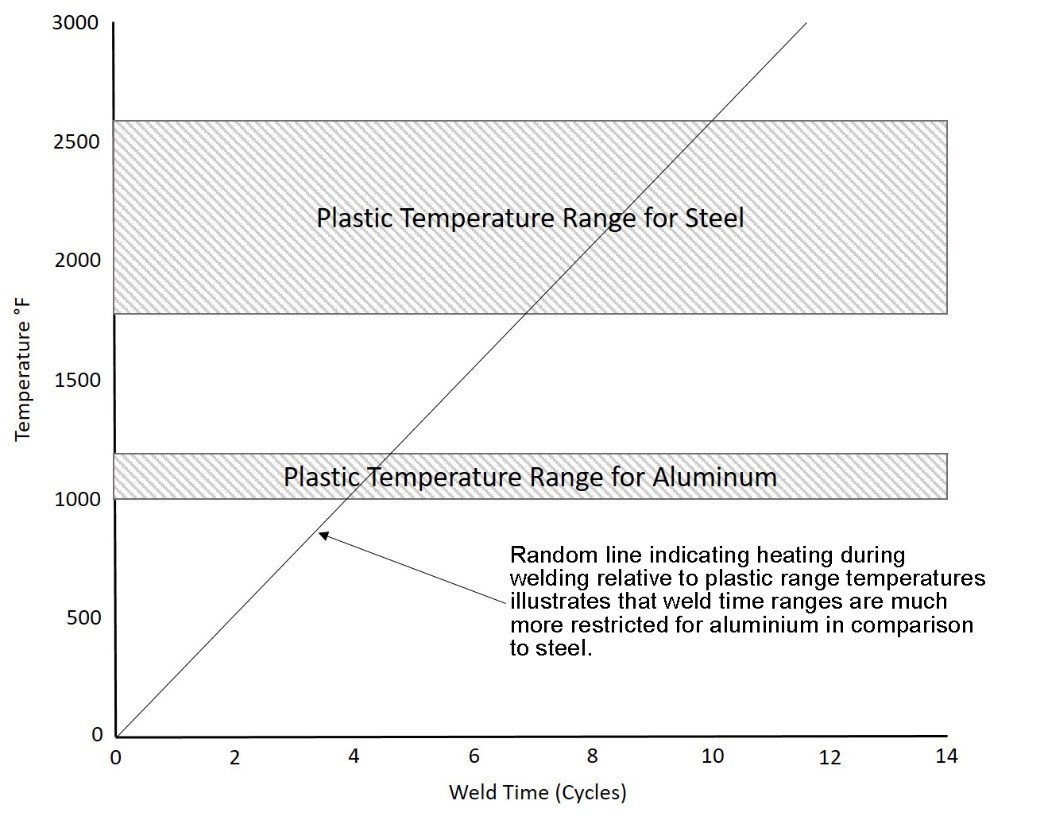
Figure 2: Typical Plastic Ranges, Steel vs. Aluminium
The plastic range of a metal can be loosely defined as the range of temperatures below its melting temperature in which the metal exhibits significant softening. The significance to spot welding is that wider plastic ranges will create a wider softened region around the weld for a longer time. This region, in conjunction with the electrode pressure, effectively “seals” the rapidly expanding (metals exhibit large volumetric expansions when they melt) molten weld nugget, and prevents it from being ejected from the weld zone (expulsion). As indicated on Figure 2 the typical plastic range of aluminum is significantly less than that of steel. The figure also includes a random heating line to illustrate the fact that a narrow plastic range not only reduces the width of the “seal” around the nugget, but also suggests that the window of welding time to produce a good weld is restricted. In summary, the narrow plastic range of aluminum combined with its low melting temperature means that the process window to create a good weld and avoid expulsion is very small.
Dynamic Resistance
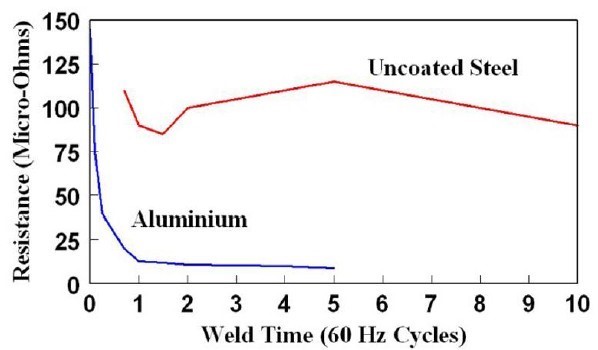
Figure 3: Dynamic Resistance Curve for
Steel Vs. Aluminium
As indicated on Figure 3, the dynamic resistance curve for aluminum is entirely different from the curve for steel. Two facts contribute to this vast difference:
1) The oxide on the surface of the aluminum, and
2) The small change in resistivity as a function of temperature.
Upon initial flow of current, resistances are extremely high due to the oxide layer which has much higher resistivity than the aluminium. This increases the likelihood of initial expulsion and will also result in significant electrode heating. The oxide layer quickly breaks down allowing current to pass more easily as resistance drops rapidly. However, as compared to the dynamic resistance curve for steel, there is no significant increase in resistance later in the cycle. The reason for this is compared to steel, aluminum’s resistivity increases only slightly with temperature as shown in Figure 3. The implication of this difference is that there is limited opportunity to grow the nugget by taking advantage of the rapid increase in resistivity, as is the case with steel.
Coefficient of Thermal Expansion
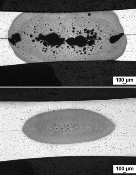
Figure 4: Aluminium Weld Discontinuities (Porosity)
Aluminum’s thermal expansion coefficient is roughly three times higher than steel. This results in greater volumetric expansion of the metal upon heating, and subsequent greater contraction upon cooling. The consequence is a greater chance not only for expulsion, but weld discontinuities such as porosity and solidification cracking (Figure 4). This may mandate the need for low inertia, fast “follow-up” weld heads which can maintain consistent force during the rapid movement of the expanding and contracting weld region. This requires more equipment and expense for the process.
Aluminium’s Oxide Layer
As discussed previously, aluminum forms an oxide layer that is tenacious and forms rapidly. The highly resistive oxide layer can be a benefit in that it significantly increases contact resistance between the sheets being welded. But maintaining a consistent oxide layer thickness is difficult since it happens naturally and rapidly as it is exposed to the environment. Because it is inconsistent, it causes inconsistencies in the weld.
On the other hand, if the oxide layer is significantly reduced by mechanical (such as grinding) or chemical (such as acid cleaning followed by a conversion treatment) methods immediately prior to welding, the need for extremely high currents will be mandated which will promote electrode sticking and accelerated wear.