Stretching is the sheet metal forming process where the punch which creates the part shape forces the sheet metal to thin since lock beads prevent metal flow inward from the flange area. In contrast with drawing, significant metal thinning occurs in stretching,...
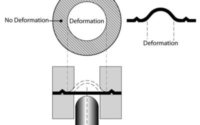
Stretching
read more