![Forming and Formability of AHSS]()
Forming
Introduction
Approaches for forming higher strength steels evolved with the commercialization of increased strength levels of High Strength Low Alloy (HSLA) steels. Demands for greater crash performance while simultaneously reducing mass and cost have spawned the development of new groups of steels that improve on the properties of these HSLA steels. Forming of Advanced High-Strength Steel (AHSS) is not a radical change from forming conventional HSLA steels, providing some of the key differences are understood and accounted for in die design, die process, and equipment selection.
AHSS grades solve two distinct automotive needs by two different groups of steels. The first group as a class has higher strength levels with improved formability and crash-energy absorption compared to HSLA grades. DP, TRIP, FB, and TWIP steels, which have increased values of the work hardening exponent (n-value), fulfill this requirement. The second group, including CP and MS steels, extends the availability of steel in strength ranges above what is available with HSLA grades. Originally targeted for chassis, suspension, and body-in-white components, AHSS grades are now being applied to doors and other body panels. New variations in microstructure help meet specific process requirements, including increased edge stretch, bendability, strengthening after forming, or tighter property tolerances.
The progressive increases in yield and tensile strength with these new AHSS grades magnifies existing forming issues with conventional HSLA grades and creates new challenges. Concerns include higher loads on processing equipment including presses, levelers, straighteners, blanking lines, coil slitting lines and roll forming equipment. Additionally, there are material and surface treatment considerations required for tooling in the stamping plants: draw dies, trim steels, and flange steels. Compared to conventional HSLA steels, greater energy requirements result from higher AHSS yield strengths, tensile strengths and significantly higher work hardening rates. This places new requirements on press capacity, leveler, straightener and slitting capabilities, tool construction/protection, lubricant capabilities, part and process design, and maintenance. Springback management becomes more critical as yield strengths continue to increase. Conventional and press hardened (hot formed) AHSS parts have very high strength after forming, so re- forming operations should be avoided. Trimming, cutting, and piercing equipment must be constructed and maintained to overcome the extreme high strength of the final stamping. Laser cutting of press hardened parts produces a finished part that avoids pushing the limits of trim and pierce tools and dies utilized for conventional HSLA steel.
There are an ever-increasing number of AHSS multiphase microstructure grades available, each designed to resist various forming failure modes while achieving final part performance requirements. Sharing of information regarding the planned part geometry, die and stamping processing, and final part application between steel suppliers, product and die process engineering, and end users helps ensure selection of the right steel grade for the application. This becomes especially relevant since multiphase microstructures experience additional forming failure modes compared with conventional high strength products.
Tool Design Considerations
The characteristics associated with different AHSS grades influence die design and die processing decisions. Not only are these steels typically higher in strength, but they also undergo substantial work hardening during forming. These lead to increased local loads, and changes in friction, die wear, and press requirements. The multiphase microstructures increase cut edge and bending fracture sensitivity. As such, extending the life and performance of tooling in press shops requires a rethinking of tool and part design.
Part Design
Successful application of any material requires close coordination of part design and the manufacturing process. Consult product and manufacturing process engineers when designing AHSS parts to understand both the limitations and advantages of the grade and the proper forming process to be employed. Start in the concept and feasibility stage to ensure sufficient time for corrective actions and optimization.
Soft tool materials like kirksite may be used for manufacturing prototype parts and the inserts used to eliminate local wrinkles or buckles. However, wear resistant coatings are typically not applied to these tool surfaces, so the metal flow seen in these prototype parts may not match the metal flow seen under production conditions. The results from soft tool tryouts should not be used to assess manufacturability and springback of AHSS parts.
Design structural frames (such as rails, sills, cross members, and roof bows) as open-ended channels to permit forming operations rather than draw die processes. AHSS stampings requiring closed-end draw operations are limited by a reduced depth of draw, Figure 1. Less complex, open-ended stamped channels are less limited in depth. A rule of thumb is that DP 350Y600T can be formed to only half the draw depth of a mild steel.

Figure 1: Schematic of an open end part design (left) and a closed end part design (right). The open-ended design allows for greater depths when utilizing AHSS versus the closed ended design historically used with mild steel.A-5
Where possible, avoid closed-end developments to make more complex geometries with AHSS grades. Wrapping ends of “hat” sections increases forming loads, increases the chances of circumferential compression wrinkling on the binder, specifically in the corners, and increases wrinkling on the draw wall if the blank edge runs through the draw bead. Draw die developments that include a closed (or wrapped) end development usually also require a larger blank size. During draw die development, it is best to identify parts that have a “hat” section geometry in certain locations and develop the draw die accordingly to maximize the positive formability attributes of AHSS while minimizing the limitations of AHSS.
For example, the left image in Figure 2 shows a draw die development on a DP600 cowl side with a closed (wrapped) end, with the right image showing a similar part developed with an open end. Although both final part geometries are similar, the closed-end development led to significant global formability failures due to the excessive stretch. In contrast, the open-ended development had virtually no global formability related failures. Other design and die development differences in the part on the right include the use of stake beads to control springback and embossments to eliminate wavy metal. In addition, an open-ended development has the potential to reduce the blank size for material utilization savings.

Figure 2: Draw die development for a cowl side formed from DP600. Left image: closed-end development with global formability failures, waviness, and springback. Right image: open-ended development with no splits, waves, or dimensional concerns.U-6
The automotive industry has adopted a strategy for “lighter dies and fewer dies”, to reduce cost. One key element is “part consolidation”, such as one-piece body side outers and inners. High strength steels challenge the part consolidation mantra. When encountering extreme formability challenges, parts previously made with one set of dies when stamped from lower strength steels may benefit from transitioning to a laser welded blank with a lower strength grade in the challenging region and higher strength steels in the remainder of the part. Alternatively, splitting the consolidated part into two or more separate parts subsequently welded together may improve stamping success at the expense of another operation. In the past, one-piece rocker panels were stamped from conventional mild or HSLA steel. However, this component requires higher strength and reduced thickness to meet weight and crash requirements, so now DP980 is often considered as the grade of choice for this application. Figure 3 shows a rocker panel where insufficient formability of DP980 prevented a one-piece stamping. The OEM solved this by dividing the part into two stampings, putting a more formable grade where needed on the wrapped (or closed) end.

Figure 3: When a one-piece rocker panel could not be successfully formed from DP980, the OEM stamped a DP980 rocker panel section with an open-ended design and spot welded it to a mild steel end cap.U-6
Trim and Pierce Tool Design
- Trim and pierce tools need to withstand higher loads since AHSS grades have higher tensile strengths than conventional high-strength steels.
- Edge cracking is minimized with proper support of the trim stock during trimming.
- Modify timing of the trim/pierce operation to minimize snap-through reverse loading.
- Scrap shedding may be an issue, since AHSS springback can cause scrap to stick in the tool.
Flange Design
- Design more formable flanges to reduce need for extra re-strike operations.
- Areas to be flanged should have a “break-line” or initial bend radius drawn in the first die to reduce springback.
- Adapt die radii for material strength and blank thickness.
Draw Bead Design
- Metal flow across draw beads generates strain and minimizes the elastic recovery which causes springback.
- Metal flow across draw beads generates large amounts of work hardening, leading to increased press loads.
- Optimizing blank size and shape reduces the reliance on draw beads, which can excessively work harden the material before entering the die opening.
Guidelines to Avoid Edge Cracking During Stretch Flanging
- Flange length transition should be gradual – abrupt changes in flange length cause local stress raisers leading to edge cracks.
- Use good cutting practices to achieve a high-quality edge.
- Avoid the use of sharp notch features in curved flanges.
- Avoid putting bypass notches in stretch or compression edges of blanks or progressive die carrier strips. These bypass notches can act as stress risers and lead to edge fractures in the draw or flange operation. In addition, bypass notches in blanks and progressive dies are difficult to maintain, which can increase the potential for edge fracture.
- Metal gainers in the draw die or in the die prior to the stretch flange operation compensates for change in length of line that occurs during flanging, helping to avoid edge cracking. In the example shown in Figure 4, edge fractures moved from the draw panel to flanged panel after grinding on the draw die to eliminate edge fractures in the draw operation. The draw panel underneath the flanged part in Figure 4 did not have edge fractures. The reduction in the length of line in the draw operation moved the problem to the flanged part where the stamping transitioned from bending and straightening in the flange operation to a stretch flange operation. A better practice is to add metal gainers to the draw panel to provide the feedstock which expands during stretch flanging.

Figure 4: Flanged panel fractures, with the draw panel underneath. Adding metal gainers to the draw panel would help minimize these fractures.U-6
- The higher strength of AHSS makes it more difficult to pull out loose metal or achieve a minimum stretch in flat sections of stampings. Addendum, metal gainers (Figures 5 and 6), and other tool features balance lengths of line and locally increase stretch.

Figure 5: Metal gainers help avoid insufficient stretched areas and eliminate buckles.T-3

Figure 6: Metal gainers and depressions balance stresses and minimizes wrinkled metal.A-41
Joining, Laser Welding
Optimizing weld morphology and mechanical properties of
laser welded Al-Si coated 22MnB5 by surface application of
colloidal graphite
Researchers at University of Waterloo discovered the microstructural effects of adding colloidal graphite to Al-Si coated 22MnB5 Press Hardened Steel.K-51 Laser welds were made on 1.5 mm thick Al-Si coated 22MnB5 PHS perpendicular to the rolling direction. Pure colloidal graphite suspended in isopropanol base was applied to the area being welded and the resulting graphite coating after evaporation ranged from 5 µm to 130 μm for testing. Parameters used for the weld are: 4kW power, 6m/min welding speed, beam diameter of 0.3 mm, and laser defocus of 6mm. Samples were then hot stamped by heating for 6 min to 930 ᵒC in a furnace and then water quenched at a cooling rate greater than 30 ᵒC/s.
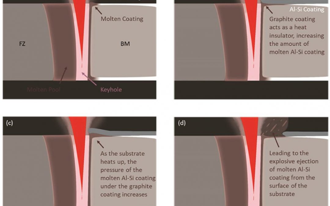
Al-Si coating is excellent at preventing oxidation and decarburization of high strength steel at elevated temperatures. However, during welding there is diffusion of Al into the fusion zone which stabilizes ferrite at elevated temperature reducing the strength of the welded joint. Colloidal graphite coating decreases the Al content and increases C content of the fusion zone. As shown in Figure 1, The mechanism for reduction in Al content is due the graphite coating acting as an insulator to the Al-Si coating which then causes an ejection of the molten Al-Si coating from the surface. Figure 2 displays a proportional reduction of Al in the fusion zone with increasing graphite coating thickness up to 40 μm where after the reduction in Al is minimal. This is attributed to the initial reduction of Al being caused by the ejection of the molten Al-Si from underneath the graphite coating. Graphite coating greater than 40 µm does not aid in additional ejection of Al-Si and the Al-Si coating already diluted in the weld pool will not be removed.
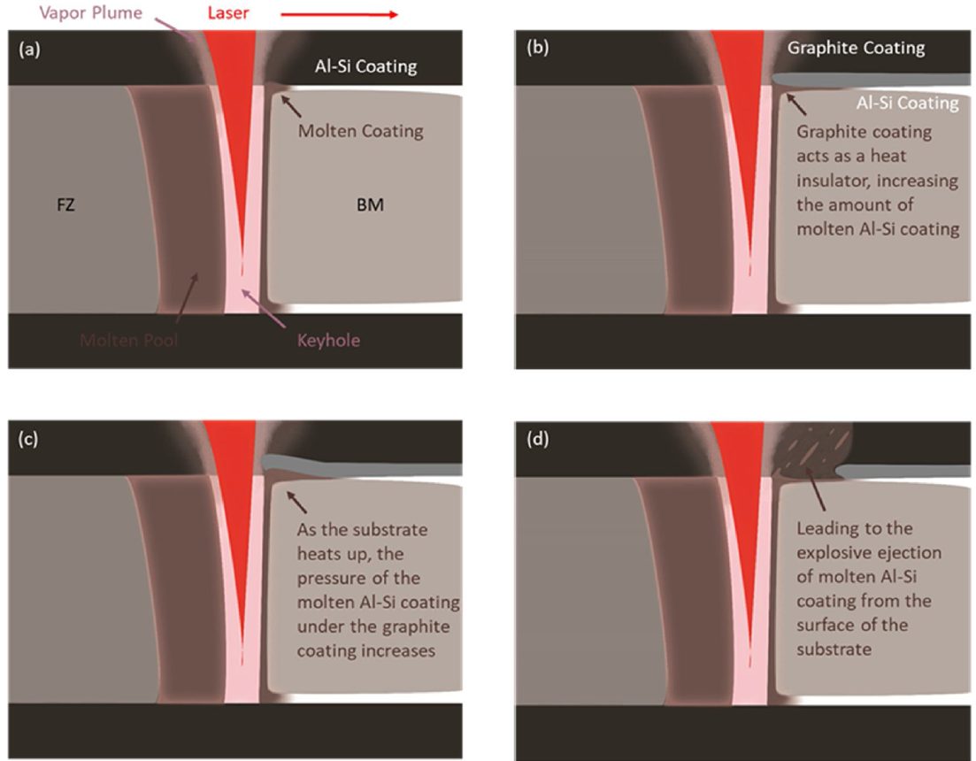
Figure 1: Al-Si ejection mechanism.K-51
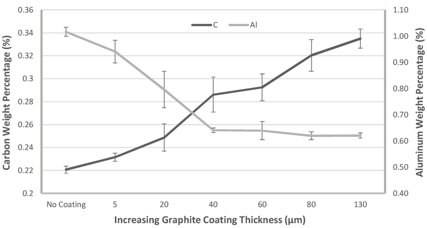
Figure 2: Al and C content in weld with increasing graphite thickness.K-51
Summary
Ferrite concentration in the fusion zone was reduced from approx. 40% with no graphite coating to approx. 2% with 130 μm graphite coating thickness (Figure 3). The increase in C content and reduction in Al content resulted in an increase in austenite being stabilized at elevated temperature rather than ferrite and therefore a larger percentage of martensite results after hot stamping. The average fusion zone hardness increased from 320 HV with no coating to 540 HV with 130 μm coating thickness (Figure 4). The weld strength of the sample with no graphite coating was 1249±15MPa whereas the weld strength with a coating of 130 µm was 1561±7MPa which matches the base metal (Figure 5). With an increase in graphite coating thickness there is an increase in weld strength that can eventually match the base metal strength.
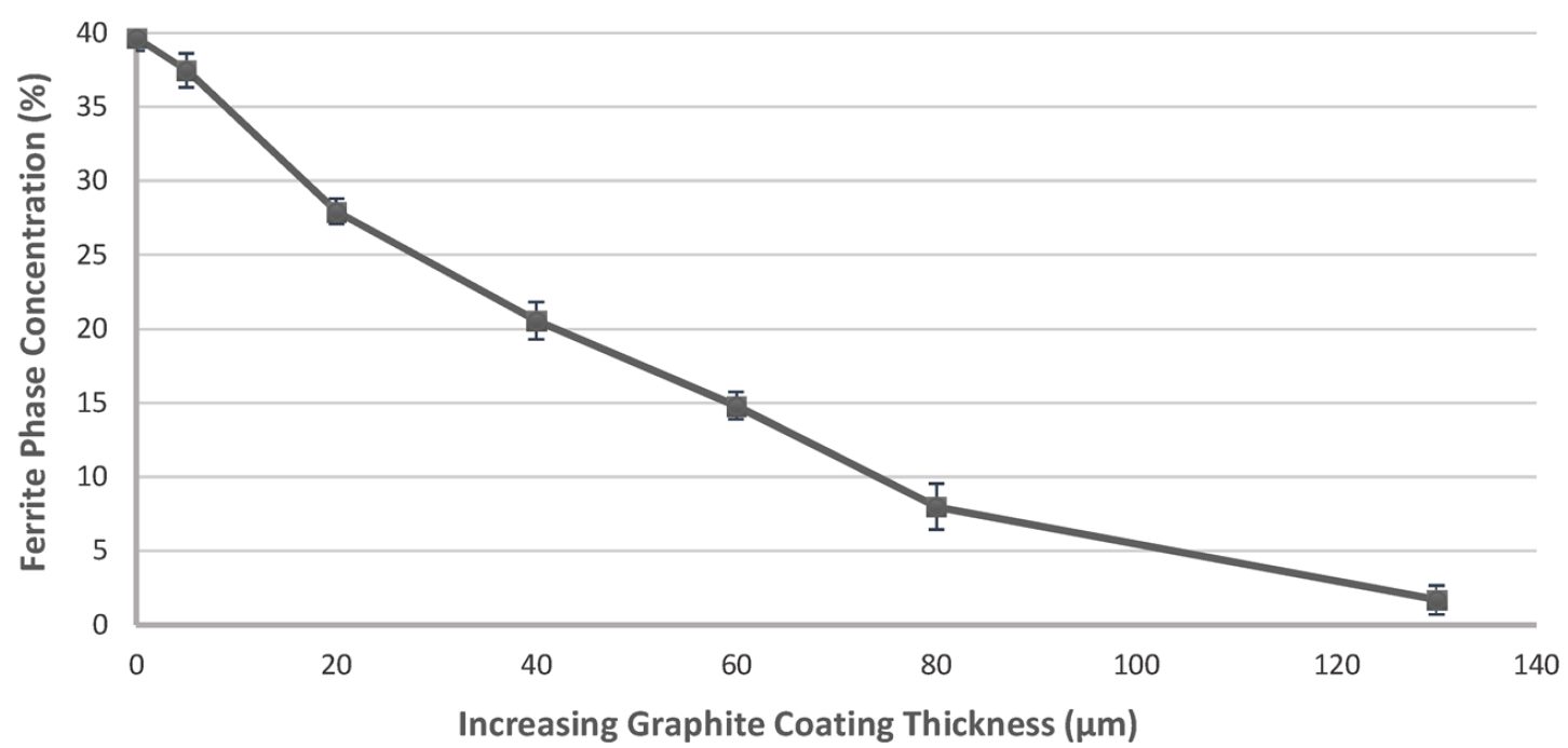
Figure 3: Ferrite concentration in weld.K-51

Figure 4: Fusion Zone Hardness vs. Graphite Thickness.K-51
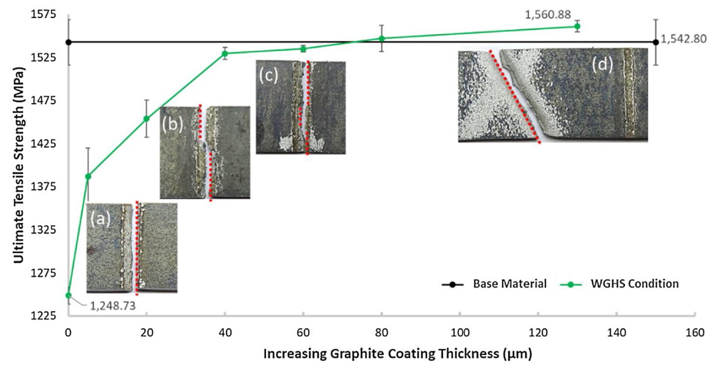
Figure 5: Weld strength vs. Graphite Thickness.K-51


