Springback
Decades ago, the major concern in sheet metal forming was elimination of necks and tears. These forming problems are a function of plastic strain, and addressing them involves maintaining strain levels in the part below specific critical strains. Forming limit diagrams, which combine the formability of the steel with the part shape and forming process, show where these critical areas fall out on the part. In-service structural requirements may result in additional limitations on allowable strains, since fatigue and durability issues may arise if too much thinning during forming occurs.
With the advances in simulation technology to predict the location of potential problems and address them before tool construction begins, the primary emphasis has shifted to accuracy and consistency of product dimensions. These dimensional problems are a function of the elastic stresses created during the forming of the part and the relief of these stresses, or lack thereof, during the unloading of part after each forming operation.
These dimensional problems or springback have always existed in sheet metal forming. However, the magnitude of springback increases as the yield strength of the steel increases. As Advanced High-Strength Steels (AHSS) usage expands due to the combination of higher strength and ductility (for enhanced formability characteristics), countering springback relative to final part dimension becomes critical. First, the design of many of the panels results in higher flow stresses, which are the combination of yield strength and work hardening during deformation. This creates higher elastic stresses in the part. Second, applying AHSS for weight reduction also requires the application of thinner sheet metal that is less capable of maintaining part shape. Third, until recently, most companies had little prior experience applying springback management procedures to their parts made from AHSS. Companies have attacked springback problems with proprietary in-house compensation procedures developed over years of trial and error in the production of various parts. An example would be specific over-crowning of a hood panel or over-bending a simple channel to allow the parts to springback to part print dimensions.
For a given part shape and sheet thickness, the springback occurring when using AHSS grades is greater than that experienced in mild or conventional HSLA steels. The magnitude of springback is a function of the as-formed flow stress, which is the strength of the sheet metal after forming. The as-formed flow stress is a function of the starting yield strength in the flat sheet as well as the work hardening which occurs from forming. Both of these are higher in AHSS grades compared with mild or conventional HSLA steels, and is the basis for the increased springback seen with AHSS.
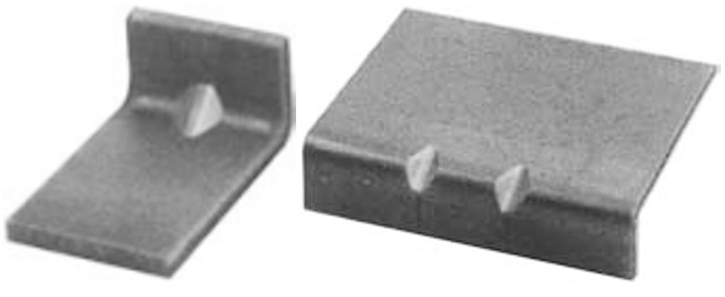
Figure 1 shows an example of this difference, where two channels of different grades were formed sequentially in a draw die with a pad on the post. The draw die was developed to attain part print dimensions with HSLA 350/450 steel. Strain distributions and lengths of line were nearly identical between the two parts. However, steel property differences between DP and HSLA steels led to different stress distributions, resulting in different dimensional accuracy.

Figure 1: Two channels made sequentially in the same die, with different mechanical properties leading to different springback.
Origins of Springback
The shape of a formed part in its free unconstrained state always deviates somewhat from the shape of punch and die after removal from the tooling. This dimensional deviation between the constrained shape within the tools under full load and after elastic recovery occurs after removing the part from the tool is known as springback.
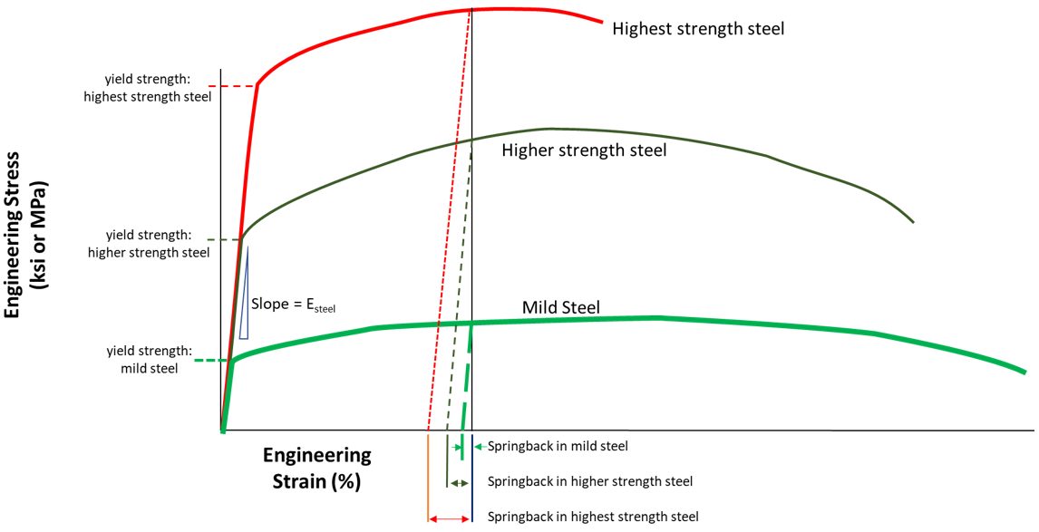
Stress-strain curves can illustrate how springback changes with material, yield strength, and work hardening. In addition to a tensile test, a stress-strain curve also shows the response of sheet metal as press load is applied to convert it from a flat blank to a formed part.
The blank starts off at the point labeled O in Figure 2, which is the origin with zero stress and zero strain. With a little loading, there is a linear stress-strain response. All deformation here is elastic, meaning that the blank will remain flat after removing the load. All deformation returns to zero providing the applied load stays below the yield strength. Once the yield strength is reached, plastic deformation begins, and the part begins to take shape. Work hardening takes over, with strength increasing as the strain in the part increases. The strength at any given strain is known as the flow stress at that strain.

Figure 2: The magnitude of springback is proportional to the elastic modulus, yield strength and work hardening of the sheet metal, in addition to the part design.E-2
Refer to the left image in Figure 2. Achieving the desired part shape work hardens the part to strength A, occurring at Bottom Dead Center of the press stroke, and resulting in strain C. Removing the part from the constraints of the die under load allows the strains to relax to strain B, relieving the elastic strains. Note how the relaxation follows a path parallel to the initial linear portion of the stress strain curve. The magnitude of BC is a representation of the springback of that part formed to the targeted shape in that location from the selected sheet metal.
Compare that against a steel with higher yield strength and higher work hardening, shown in central image of Figure 2. Achieving the part shape work hardens this steel to strength A’, also reaching strain C since the part shape did not change. After removing this part from the tool, it is free to move to its unconstrained shape. Again, the relaxation follows a path parallel to the initial linear portion. In this case, the strains relax to strain B’. The higher yield strength and work hardening leads to B’C > BC, or a greater amount of springback.
The slope of the initial linear portion of stress-strain curves is known as Young’s Modulus, the Elastic Modulus, or the Modulus of Elasticity. For all steel grades, it is essentially constant at approximately 210 GPa, which is why the slope of that initial section is the same in the left and center images of Figure 2. However, the Elastic Modulus of automotive aluminum alloys is approximately 70 GPa, or ⅓ that of steel. The effect on the stress-strain curve is that the slope of the initial portion decreases by ⅓. This difference in modulus results in aluminum alloys having three times the springback of a similar strength steel, as shown by B’’C in the right image of Figure 2. If higher strength aluminum alloys capable of forming the chosen design exists, springback will be even greater in these parts without making other changes to the product and process.
Although the recovered elastic strains at a given location are relatively small relative to plastic strains in formed parts (on the order of 0.01 % elastic vs. 10 % plastic), they can cause significant shape changes due to its mechanical multiplying effect on other locations when bending deformation and/or curved surfaces are involved. Free edges lack the constraints of the central portion of panels, and therefore are most likely at risk for dimensional issues.
The tooling and component geometry also influence the magnitude of springback. When part geometry prevents complete unloading (relaxing) of the elastic stresses, residual stresses is the term for the constrained elastic stresses remaining in the part. The part takes whatever shape it can to minimize the total remaining residual stresses, either through twisting, bending, or other metal motion. Door panels present an example. The panel coming out of the draw die may have the desired dimensions, but challenges may arise after punching the window cutout and other access holes.
Methods for correcting springback are described here.
Types of Springback
Three modes of springback commonly found in channels and underbody components are angular change, sidewall curl, and twist.
Angular Change
Angular change, or springback, is the angle created when the bending edge line (the part) deviates from the line of the tool. The springback angle is measured as the deviation from the punch radius (Figure 3). If there is no sidewall curl, the angle is constant up the wall of the channel.
Angular change results from the stress difference in the sheet thickness direction when the sheet metal bends over a radius during forming. This stress difference in the sheet thickness direction creates a bending moment at the bending radius. Eliminating or minimizing the angular change requires elimination or minimization of this bending moment.

Figure 3: Schematic showing difference between angular change and sidewall curl.
Sidewall Curl
Sidewall curl is the curvature created in the side wall of a channel (Figures 1 and 3). This curvature occurs when a sheet of metal is drawn over a die/punch radius or through a draw bead. The primary cause of this curl is an uneven stress distribution or stress gradient through the thickness of the sheet metal generated during the bending and unbending process.
During the bending and unbending sequence, the deformation histories for both sides of the sheet are unlikely to be identical due to the differing degrees of tension and compression on each surface. This usually manifests itself by flaring of the flanges, which is an important area for joining to other parts. The resulting sidewall curl can cause assembly difficulties for rail or channel sections that require tight tolerance of mating faces during assembly. In the extreme, a gap resulting from the sidewall curl can be so large that welding is not possible.
Figure 4 illustrates in detail what happens when drawing a sheet metal over the die radius. This bending-unbending process on side A changes from tension (A1) during bending to compression (A2) during unbending. In contrast, the deformation on side B changes from compression (B1) to tension (B2) during bending and unbending. As the sheet enters the sidewall, side A is in compression and side B is in tension, although both sides may have similar amounts of strain. Once the punch is removed from the die cavity (unloading), side A tends to elongate and side B to contract due to the elastic recovery causing a curl in the sidewall.

Figure 4: Origin and mechanism of sidewall curl.
The main source of variation in sidewall curl along the wall comes from the difference in elastic recovery on sides A and B. The higher the strength of the deformed metal, the greater the magnitude and difference in elastic recovery between sides A and B and the associated increase in sidewall curl. The strength of the deformed metal depends not only on the as-received yield strength, but also on the work hardening capacity. This is one of the key differences between conventional HSLA and AHSS. Minimizing the sidewall curl requires minimizing the stress gradient through the sheet thickness.
Strain hardening differences between conventional HSLA and AHSS explain how the relationship between angular change and sidewall curl can alter part behavior. Figure 5 shows the crossover of the true stress – true strain curves when comparing two steels of equal tensile strengths, noting the AHSS grade has a lower yield strength than the conventional HSLA grade.

Figure 5: Schematic description of the effect of hardening properties on springback.K-4
At the lower strain levels usually encountered in angular change at the punch radius, AHSS grades have a lower level of stress and therefore less springback. The predominant trend is increasing angular change for increasing steel strength, as shown in Figure 6, which highlights a nearly linear relationship between tensile strength and angular change.

Figure 6: Angular change increases with tensile strength.K-4
Sidewall curl is a higher strain event because of the bending and unbending of the steel going over the die radius and any draw beads. For the portions of the two stress–strain curves shown in Figure 5, the AHSS grade now is at a higher stress level with increased elastic stresses. Therefore, the sidewall curl is greater for the AHSS grade, as indicated in Figure 7.

Figure 7: Sidewall curl increases with tensile strength.N-2
Remember that AHSS grades have lower yield strength at a given tensile strength. If Figure 5 compared instead a conventional high strength steel grade and an AHSS grade at the same yield strength rather than the same tensile strength, the stress strain curve for the AHSS grade would plot above that for the conventional HSLA grade. In this comparison, the AHSS channel will have greater springback for both angular change and sidewall curl compared to the HSLA channel, and would appear similar to Figure 1.
These phenomena are dependent on many factors, such as part geometry, tooling design, process parameter, lubrication, and material properties. However, higher work-hardening of DP and TRIP steels causes greater increases in the strength of the deformed steel for the same amount of strain.
Any differences in tool build, die and press deflection, location of pressure pins, and other inputs to the stamping can cause varying amounts of springback – even for what should be completely symmetrical parts.
Twist
Twist occurs when two cross sections within the same part rotate differently along their axis, and results from torsion moments in the cross section of the part. The torsional displacement (twist) develops because of unbalanced springback and residual stresses acting in the part to create a force couple, which tends to rotate one end of the part relative to another. As indicated in Figure 8, the torsional moment can come from the in-plane residual stresses in the flange, the sidewall, or both.

Figure 8: Torsion Moment created flange or sidewall residual stresses.Y-2
The actual magnitude of twist in a part is determined by the relationship between unbalanced stresses on the part and the stiffness of the part in the direction of the twist. Low torsional stiffness values in long, thin parts are the reason high aspect ratio parts have significantly higher tendencies to twist. There is also a lever effect, whereby the same amount of twist will result in a larger displacement in a long part than would be the case in a shorter part with a similar twist angle. Twisting is more prone to occur in a thin sheet metal component with large differences in sectional dimensions, such as rails and shallow panels with nearly flat surfaces.
Overcoming the tendency for parts to twist requires reducing the imbalance in the residual stresses forming the force couple that creates the torsional movement. Unbalanced forces are more likely in unsymmetrical parts, parts with wide flanges or high sidewalls, and in parts with sudden changes in cross section. Parts with unequal flange lengths or non-symmetric cut outs are susceptible to twist due to unbalanced springback forces generated by these non-symmetrical features.
Even in geometrically symmetrical parts, unbalanced forces can be generated if the strain gradients in the parts are non-symmetrical. Some common causes of non-symmetrical strains in symmetrical parts are improper blank placement, uneven lubrication, uneven die polishing, uneven blankholder pressure, misaligned presses, or broken/worn draw beads. These problems will result in uneven material draw-in with higher strains and higher elastic recoveries on one side of the part compared to the other, thereby generating a force couple and inducing twist.
Twist can also be controlled by maximizing the torsional stiffness of the part – by adding ribs or other geometrical stiffeners or by redesigning or combining parts to avoid long, thin sections that will have limited torsional stiffness. Minimize twisting potential by:
- Avoiding sudden changes of cross section shape.
- Equalizing the forming depth where possible.
- Optimizing the blank shape to balance deformation.
- Minimizing the flange length normal to the part.
- Incorporating geometric stiffeners like beads or additional flanges.
- Modifying the trim process and sequence to balance stresses.
Global Shape Change
Global shape changes, such as reduced curvature when unloading Class-A surface panel in the die, are usually corrected by the springback management measures described below. The key problem is minimizing springback variation during the run of the part and during die transition. One study showed that the greatest global shape (dimensional) changes initiated from inconsistent die setting practices.A-40
Surface Disturbances
Surface disturbances on Class-A surface panels develop from the reaction to local residual stress patterns within the body of the part. Common examples are high and low spots, oil canning, and other local deformations that form to balance total residual stresses to their lowest value.
Case Study in Springback PredictionO-4
Accurately modeling springback requires knowledge of the yield strength and the hardening behavior during the non-linear strain path followed by each element of the part as the flat blank deforms to the final shape. Part of the challenge stems from the bending-unbending sequence as the sheet metal passes over beads and die radii, leading to what is known as the Bauschinger effect. The Bauschinger effect causes the yield strength to decrease each time the sheet undergoes the tension-compression associated with each bend-unbend, explained graphically in Figure 9.

Figure 9: Graphical explanation of Bauschinger Effect.
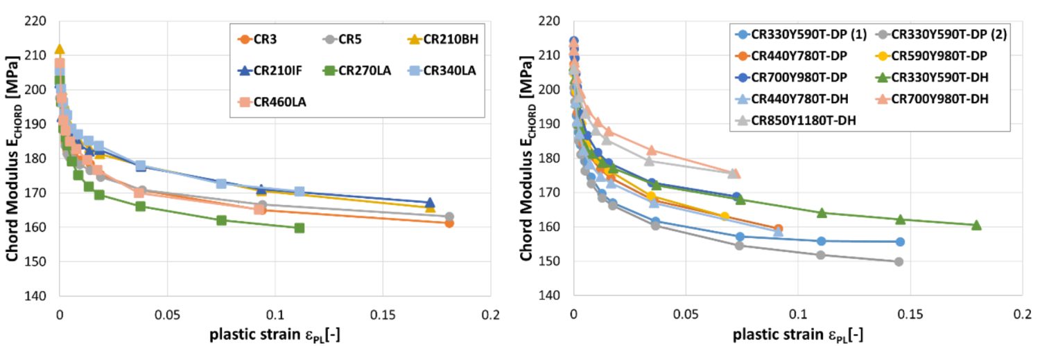
In addition to the reduced yield strength from each bend-unbend, the Chord Modulus also decreases each time due to dislocation density evolution, which increases very quickly at the beginning of the plastic deformation. This reduction can be as much as 20% from the value determined in the as-produced steel, as shown in Figure 10.

Figure 10: Chord Modulus decreases after bending-unbending.
The basic mechanism of the Bauschinger Effect is related to the dislocation restructuring during nonlinear deformation, which means it is a function of the steel grade, part shape, and forming process design. These variables make it impossible to have one generic interpretation applicable for all grades and parts. Instead, detailed testing is needed for accurate application of the information.
Modeling these effects accurately is critical in achieving satisfactory springback predictions. A basic isotropic hardening model is insufficient for most stampings, since it assumes that strength is the same in tension and compression – in other words, that there is no Bauschinger Effect. This approach is certainly simpler, but cannot predict springback since it does not reflect physical reality.
Kinematic hardening models, such as the Yoshida‐Uemori (YU) model, do account for the Bauschinger Effect, but this type of model is best applied in linear sections where there is a simple reversal in strain path.Y-7,Y-8
However, many challenging parts have stretch flange sections and curved walls, like seen in the B-Pillar of Figure 11. In this figure, using the YU model for the areas in green leads to inaccuracies due to the multi-directional metal flow.

Figure 11: Using the YU model for the cross loading seen in circled area leads to inaccurate springback predictions.
To account for this cross-loading seen in curved walls, a Homogeneous Anisotropic Hardening (HAH) model was developed.B-10, L-19 Although the specific details of these models are beyond the scope of this article, the yield surface of the YU model consists of three surfaces translated dependently, where instead the yield surface of the HAH model is homogeneous and distorted.
The models were benchmarked against S-Rail test samples made from 1.4mm thick martensitic steel with a tensile strength of 1500 MPa, indicated in Figure 12.

Figure 12: Benchmarked samples made from 1.4 mm martensitic steel with 1500MPa tensile strength.
Material parameters for the YU model and the HAH model were identified and optimized with tension-compression-tension experiments. As shown in Figure 13, the HAH Model provided a better dimensional match to the physical samples.

Figure 13: Homogeneous Anisotropic Hardening (HAH) model matches physical test samples better than the YU model.
Key Points
The potential for springback (angular change, sidewall curl, and twist) increases as the flow stress (the strength after forming) increases. AHSS parts are at greater risk of springback, since parts made from AHSS have high flow stresses arising from their higher strength as produced at the steel mill combined with higher work hardening characteristics compared with conventional HSLA grades.
Sharp bend radii, tight die clearance, and higher binder pressure minimize springback and springback variation. However, formability characteristics of AHSS grades make simultaneously achieving these design features more challenging. Press capability must be sufficient to apply the higher binder pressure, and well as satisfying the necessary forming load and energy requirements.
Drawing or stretching over a radius increases springback. A forming die with an upper pad minimizes drawing over a radius in channel shaped parts, but the risk of sidewall curl exists. When draw forming, ensure sufficient restraining force in the binder with the use of higher blank holding force or draw/lock beads which increase sidewall tension. Stretch-forming produces a stiffer panel with less springback than drawing.
Asymmetric parts and part design promote the conditions for a part to twist by increasing the torsion moment associated with the residual stress in the flange and sidewall. Twisting potential increases with AHSS grades.
Achieving dimensional precision may require multiple stage forming processes or secondary operations. A crown existing in the first step of a channel section may need a second die for flattening and eliminating sidewall springback. Remember that each step work hardens the steel to higher strength levels, reducing the formability and increasing press load and energy requirements.
Methods for correcting springback are described here. The testing needed to calibrate advanced material models for improved springback simulation are described here.