Coatings for PHS
Overview
The initial press hardening steels of the 1970s were delivered bare, without a galvanized or aluminized layer for corrosion protection (i.e., uncoated). During the heating process, an oxide layer of FeOx forms if the furnace atmosphere is not controlled. Through the years, several coating technologies have been developed to solve the following problems of uncoated steels:F-14, F-33
- Scale formation, which causes abrasive wear and requires a secondary shotblasting process before welding,
- Decarburization, which leads to softening close to the surface,
- Risk of corrosion.
The first commercially available coating on press hardening steels was patented in 1998. The coating was designed to solve the scaling problem, but it also offered some corrosion resistance.C-24 Since the coating composition is primarily aluminium, with approximately 9% silicon, it is usually referred to as AlSi, Al-Si, or AS.
Coating thickness is nominally 25 μm (75 g/m2) on each side and referenced as AS150. A more recent offering is a thinner coating of approximately 13 μm, and is referenced as AS80.A-51 The AS coating requires a special heating curve and soaking time for better weldability, corrosion resistance and running health of the furnace. Most OEMs now include furnace dew point limitations to reduce/avoid hydrogen embrittlement risk.
In 2005, Volkswagen was looking for a method to manufacture deep drawn transmission tunnels and other complex-to-form underbody components using press hardened steels. Although AS coatings were available, parts could not be formed to the full draw depth using the direct process, and the coating on the AS coated blanks cracked during the cold forming portion of the two-step hybrid process. Using uncoated blanks led to severe scale formation, which increased the friction coefficient in hot forming. For this particular problem, a varnish coating was developed. The coating was applied at a steel mill, and shipped to Volkswagen’s stamping plant. The varnish coated blanks were first cold pre-formed and then heated in a furnace, as seen in Figure 1a. Hot pre-forms were then deep drawn to full depth tunnels. As shown in Figure 1b, scale formed on parts which did not have the coating. A varnish coated blank could be cold formed first without crack formation in the coating, and then hot formed without any scale, Figure 1c.S-63, F-34 Since then, some other varnish coatings also have been developed.

Figure 1: Transmission tunnel of 6th generation Volkswagen Passat (2005-2014): (a) hot forming of pre-form, and final parts: (a) uncoated blank would suffer from scaling, (c) scale-free parts can be formed from varnish-coated blanks.F-34
In car bodies, components that are sealed from external moisture are referred to as dry areas. These areas have low risk of corrosion. Areas that may be exposed to moisture are wet areas. Precautions must be taken to avoid corrosion of the sheet metal, such as using galvanized or pre-coated steel. Sealants can also be applied to joints to keep out moisture. The presence of humidity in these areas increases the risk of forming a galvanic cell, leading to accelerated corrosion. These areas have higher risk of corrosion and may require additional measures. Figure 2 shows dry and wet areas. In this figure, parts colored with yellow may be classified as wet or dry, depending on the vehicle design and the OEMs requirements.G-41

Figure 2: Dry and wet areas in a car body. (re-created after G-41)
An estimated ~40% of press hardened components are in dry areas. Thus, high corrosion protection is desired in the 60% of all press hardened components which are employed in wet areas.B-48 Zn-based coatings are favored for their cathodic protection, but require tight process control. The first commercial use of Zn-coated PHS was in 2008, using the indirect process.P-20 Since then, direct forming of Zn-coated PHS has been studied. When direct formed, furnace soaking temperature and time must be controlled carefully to avoid deep microcracks.G-41, K-20 Recently developed are two new Zn-coated press hardening steel grades, 20MnB8 and 22MnSiB9-5, both reaching approximately 1500 MPa tensile strength after processing. Using these grades requires a pre-cooling process after the furnace to solidify the Zn-based coating. 20MnB8 can be direct hot formed after pre-cooling, whereas 22MnSiB9-5 can be formed in a transfer press in the “multi-step” process.K-21, H-27
Depending on the coating type and thickness, the process type, controls and investment requirements may change significantly. For example, some press hardening lines may be designed to form blanks with only Al-based coatings. Table 1 summarizes the advantages and disadvantages of several coating systems.
| Coating Type | Advantages | Disadvantages |
|---|---|---|
| Uncoated |
|
|
| Al-Based |
|
|
| Zn-Based |
|
|
| Varnish |
|
|
Uncoated Blanks
The earliest press hardening steels did not have any coating on them. These steels are still available and may be preferred for dry areas in automotive applications. If the steel is uncoated and the furnace atmosphere is not controlled, scale formation is unavoidable. Scale is the term for iron oxides which form due to high temperature oxidation. Scale thickness increases as the time in furnace gets longer, as seen in Figure 3. Scale has to be removed before welding, requiring a shotblasting stage. Thicker scale is more difficult and more costly to remove.M-53 Early attempts to reduce (if not avoid) scale formation saw the use of an inert-gas atmosphere inside the furnace.A-52 Today, a mixture of nitrogen (N2) and natural gas (CH4) is typically used.F-35 In China, at least one tier supplier is using a vacuum furnace to prevent scale formation.A-68

Figure 3: Oxide layer (scale) on press hardened steel after: (a) fast resistance heating (10 seconds in air), (b) furnace heating (120 seconds in air).M-53
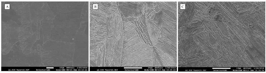
While heating uncoated steel in the furnace, if the conditions are favorable for iron (Fe) oxidation, carbon (C) may also be oxidized. When the carbon is oxidized, layers close to the surface lose their carbon content as gaseous carbon monoxide (CO) and/or carbon dioxide (CO2) is produced.S-87 The depth of the “decarburization layer” increases with dwell time in the furnace, until an oxide layer (scale) formed. Scale acts as a barrier between the bare steel and atmosphere. As the carbon is depleted in the “decarburization layer”, the hardness of the layer is decreased, as seen in Figure 4. Decarburization is usually undesirable since it lowers the strength/hardness and may negatively affect fatigue life.C-26

Figure 4: Hardness distribution of an uncoated steel after 6 minutes in a 900 °C furnace, showing hardness decrease as the surface layers lose their carbon. (Re-created after C-26.
Several methods are available to improve the corrosion resistance of uncoated PHS parts:
- E-coating after welding, before painting is a typical step of car body manufacturing, for rustproofing.
- If descaling can be done by using chromium shots (in shotblasting), a thin film of chromium-iron may grow on the surface and improve the corrosion resistance.F-14
- Vapor galvanizing (also known as Sherardizing) of uncoated steel after descaling, an experimental study described in Citation G-42.
- Electro-galvanizing after hot stamping, as described in Citation A-68.
- Change the base metal chemistry to one that is more oxidation resistant.L-60 Figure 5 compares the shiny non-oxidized surface appearance of parts made from this grade with that made from a conventional uncoated press hardening grade on the same production line with the same processing conditions.W-28

Figure 5: Oxidation resistant PHS grades may not need descaling or coatings for sufficient corrosion resistance. (re-created after W-28).
Aluminium-Based Coatings
The first commercially available coating on press hardening steels was patented by Sollac (now part of ArcelorMittal) in 1998. This coating was designed to address the scaling problem, but also offers some barrier corrosion resistance.C-24 The nominal coating composition is 9-10 wt.% Si, 2-4 wt.% Fe, with the balance Al.L-39 The coating may be referred to as AlSi, Al-Si, AluSi or more commonly AS. Nominal as-delivered coating thickness is 25 μm (approximately 75 g/m2) on each side, and is usually referred to as AS150, with 150 referencing the total coating weight combining both sides, expressed as g/m2. More recently, a thinner coating of 13 μm (30-40 g/m2 on each side, AS60 or AS80) is now commercially available.A-51 When AS coated blanks are “tailor rolled,” the coating thickness is also reduced in a similar percentage of the base metal thickness reduction. Corrosion protection is similarly reduced, and furnace parameters need to be adjusted accordingly.
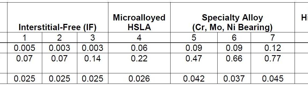
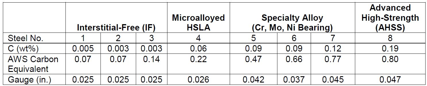
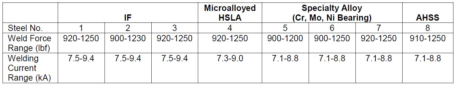
As delivered, AS150 has a coating thickness of 20-33 μm and a hardness of approximately 60 HV. The “interdiffusion layer” (abbreviated as IDL) has a high hardness and low toughness at delivery, as seen in Figure 6a. Due to the brittle nature of the IDL, AS coated blanks cannot be cold formed unless very special precautions are taken. During heating, iron from the base metal diffuses to the coating forming very hard AlSiFe (or AlFe) layers close to surface. At the same time, Al and Si of the coating diffuse to the IDL, growing it in thickness and reducing its hardness, Figure 6b. Earlier studies have shown that heating time (and also furnace temperature) has direct effect on the final thickness of IDL, as shown in Figure 7. Once the IDL thickness surpasses approximately 16 to 17 μm, the welding current range (ΔI = Iexpulsion – Imin) may be well below 2 kA.V-15, V-21, W-34 The dwell time must be long enough to ensure proper surface roughness (see Figure 6b) for e-coatability.M-27, T-40 Figure 10 summarizes the heating process window of AS coatings. The process window may change with base metal and coating thicknesses.

Figure 6: AS coating micrographs: (a) as-delivered, (b) after hot stamping process (re-created after V-15, V-21, W-34, G-32)

Figure 7: IDL thickness variation with furnace dwell time (Image created by B-55 using raw data from V-21, G-32, K-41.)
Hydrogen induced cracking (HIC, also known as hydrogen embrittlement) has been a major problem for steels over 1500 MPa tensile strength. AS coated steels may have higher diffusible hydrogen, when delivered, due to the aluminizing process occurring at 680 °C. In addition, AS coated grades may have a hydrogen absorption rate up to three times higher during heating.C-27 To reduce the hydrogen diffusion, it is essential to control the heating process (both heating rate and dew point in the furnace). AS coated blanks absorb hydrogen at room temperature; however, this happens at much lower rates than uncoated or Zn-coated blanks.J-21 Diffusible hydrogen can be removed from the press hardened part by re-heating the part to around 200 °C for 20 minutes or longer, in a process called de-embrittlement.V-21, G-32, G-43, J-21
For the abovementioned reasons, AS coated higher strength grades (i.e., PHS1800 and over) are required to have precise “dew point regulations” during the heating in furnace. Their final properties, especially elongation and bending angle, may be guaranteed only after paint baking, as shown in Figure 8.B-32 Paint baking is standardized in Europe as a treatment for 20 minutes at 170 °C, which may act like a de-embrittlement treatment.E-10 Some OEMs also require dew point control and “subsequent de-embrittlement treatment” for AS coated PHS1500. This is typically done by the tier supplier, before the paint baking process.

Figure 8: Effect of diffusible hydrogen (Hdiff) on mechanical properties of: (a) uncoated PHS2000, (b) AS coated PHS2000 in an uncontrolled furnace atmosphere (re-created using raw data from C-27).
Another method to reduce the risk of hydrogen embrittlement is to adjust the coating composition. The bath chemistry for a standard AS coating consists of up to 90% aluminium, about 8% to 11% silicon and a maximum of 4% iron. Adding a maximum of 0.5% alkaline earth metals, like magnesium, for example has been shown to result in 40% less hydrogen diffusion into steel.R-29, T-45
Although not common in the industry, Al-Zn and Zn-Al-Mg based coatings have also been developed for press hardening processes.F-14 Recently introduced is an aluminium-silicon coating with magnesium additions. When oxidized with water vapor, Mg releases less H2 and thus may reduce the diffusible hydrogen.S-88
AS coatings may cause costly maintenance issues in roller hearth furnaces, as the coating may contaminate the rollers.B-14 Special care has to be taken to avoid the issue or prolong the maintenance intervals.
Zinc-Based Coatings
AS coatings provide some corrosion protection, known as “barrier protection”, as the coating forms a barrier between the oxidizing environment and the bare steel. It is quite common in Europe for a car to have 12 years corrosion protection warranty. To achieve such corrosion resistance, a typical car may have over 85% of its components galvanized.S-89
The use of Zn-coated PHS has been relatively low, compared to AS coated and uncoated grades. In 2015, 76% of the PHS sold in EU27+Turkey was AS coated. In these markets, 18% of the PHS sold was uncoated and only 6% was Zn coated.D-20 This can be attributed to the susceptibility of Zn-coated PHS to Liquid Metal Embrittlement (LME, also known as Liquid Metal Assisted Cracks (LMAC) and Liquid Metal Induced Embrittlement (LMIE)).C-28, L-46
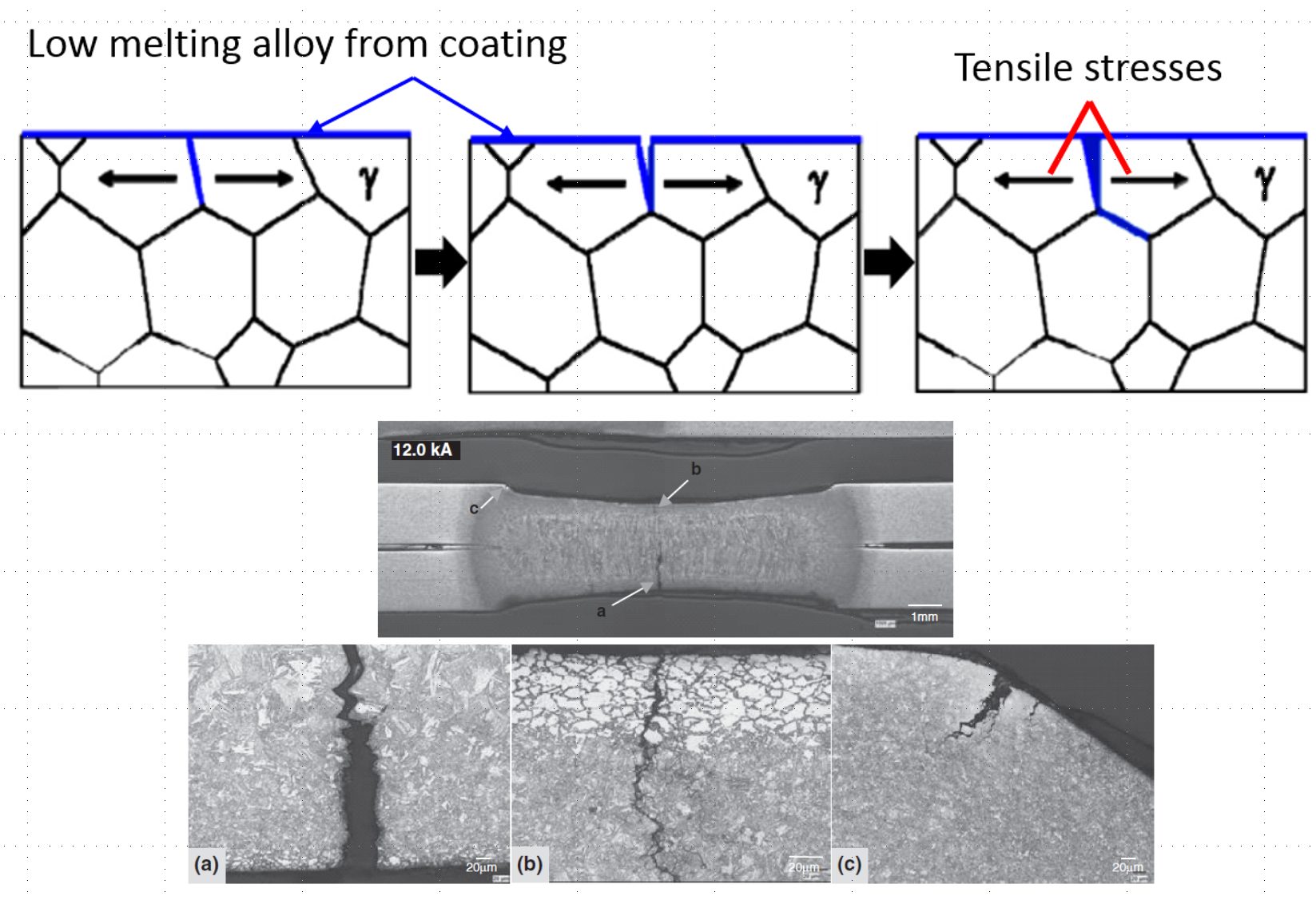
After heating and soaking in the furnace, the base metal should be in the austenitic phase. During heating, the Zn coating reacts with the base metal and forms a thin solid layer of body-centered-cubic solid solution of Zn in α-Fe, shown as α-Fe(Zn) in Figure 9. During deformation, a microcrack can be initiated in this layer at the grain boundaries of the austenite in the base metal, as indicated in Figure 9a. As the crack propagates, zinc from the α-Fe(Zn) layer diffuses along the austenite grain boundary and combines with iron from the base steel to form additional α-Fe(Zn), Figure 9b. Cracks propagate through the weak a-Fe(Zn) grain boundary layer, allowing liquid zinc (with diffused iron) to advance into the capillary crack (Figure 9c). After quenching, the base metal transforms to martensite and the liquid Zn transforms to a hard and brittle intermetallic phase, Γ-Fe3Zn10.C-28

Figure 9: Schematic illustration of microcrack formation. (re-created based on C-28.)
To avoid LME, three methods can be employedK-20:
- Forming in the absence of liquid Zn,
- Reducing stress level,
- Reducing material susceptibility.
There are no breakthroughs to address the last two items. Forming a part in the absence of liquid Zn involves either of two process routes:
- Indirect press hardening (also known as form hardening), or
- Pre-cooled processes:
In the direct forming of Zn-coated blanks, with or without pre-cooling, microcracks in the base metal may be observed. Microcracks less than 10 μm into the base metal does not affect the fatigue strength of the part.K-20 Microcrack depth is a function of coating thickness, furnace conditions (temperature and dwell time, see Figure 10), forming severity and forming temperature. It may be possible to direct form galvannealed (GA coated, ZF or ZnFe in the coating) blanks.
The boiling point of pure zinc (907 °C) is very close to the austenitization temperature of 22MnB5 (885 °C), so the heating process window of Zn-coated blanks must be controlled precisely. When the furnace dwell time is too short, deeper microcracks may be observed. When the furnace dwell time is too long, corrosion performance may be degraded. Thus, heating process window of Zn-coated blanks is significantly narrower than that of AS-coated blanks, as seen in Figure 10.B-14, S-90

Figure 10: Heating process window of AS and Zn coatings (representative data, may not be accurate for all sheet and coating thicknesses, re-created based on B-14, S-90.
Zn-based coatings may result in very low diffusible hydrogen after press hardening. In one studyJ-21, no diffusible hydrogen was detected, as long as the furnace dwell times are shorter than 6 minutes. Even after 50 minutes in the furnace, diffusible hydrogen was found to be around 0.060 ppm. Zn coatings do not act as a barrier for hydrogen desorption (losing H through the surface). Even at room temperature, Zn coated blanks may lose most of the diffusible hydrogen within a few days (also referred to as aging). See Figure 11.

Figure 11: Evolution of galvanized coating: (a) as delivered: Ferrite+Pearlite in base metal, almost pure Zn coating with Al-rich inhibition layer, (b) at high temperatures: austenite in base metal + α-Fe(Zn) and liquid Zn + surface oxides, (c) after press hardening: martensite in base metal + α-Fe(Zn) and Γ-phase coatings + surface oxides. The oxides are removed prior to welding and painting.J-21
Zn-based coatings may have a yellowish color after hot stamping. The surface oxides have to be removed before welding. This is typically done by shotblasting.
PHS blanks with a ZnNi coating were previously available. The ZnNi coating provided a low friction coefficient, a large process window in the furnace, the ability to be cold formed (indirect or two-step hybrid processes were also possible) and decreased susceptibility to LME.B-56 ZnNi coated PHS was used in the rear rail of the Opel Adam city carH-57 for a short period, until the coating was discontinued.C-29
Varnish Coatings
Another method to avoid scaling and decarburization is to apply varnish coatings, Figure 12. In this method, uncoated steel can be either coil coated or blanks can be manually coated with the paint-like varnish coatings.B-14 These coatings may also be referred to as “paint-type” or “sol-gel”.

Figure 12: Manual application of a varnish coating.F-34
Depending on the type of coating, they may allow very fast heating – including induction and conduction heating with electric current. Since the coating does not require time to diffuse, furnace heating may be completed in less than 2 minutes.F-34 Again, depending on the type, surface conditioning may not be required before welding or e-coating.B-14
They were used in automotive industry between 2005 and 2010. By 2015 there were four different types of varnish coatings, some of which are now discontinued.B-14 These coatings may be useful for prototyping and low volume production.
 |
Thanks are given to Eren Billur, Ph.D., Billur MetalForm, who contributed this article. |