High Energy Density Welding Processes
Fundamentals and Principles of High Energy Density Welding
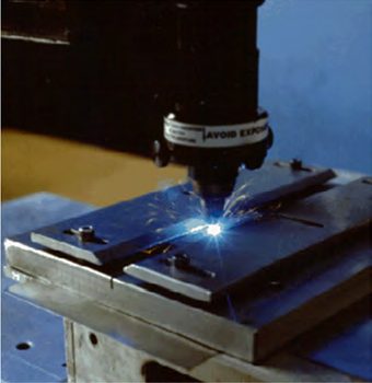
High energy density welding processes are those that focus the energy needed for welding to an extremely small size area. This allows for very low overall heat input to the workpiece, which results in minimal BM degradation, residual stress, and distortion. Welding speeds can be very fast. The two main processes known for extreme energy densities are laser (Figure 1) and Electron Beam Welding (EBW).
Figure 1: Laser welding.
As shown in Figure 2, energy densities of focused laser and electron beams can approach and exceed 104 kw/cm2. These energy densities are achieved through a combination of high power and beams that are focused to an extremely small diameter. Diameters as small as a human hair (0.05 mm) are possible. PAW[KH1] offers greater energy density than conventional arc welding processes and is sometimes referred to as the “poor man’s laser”.
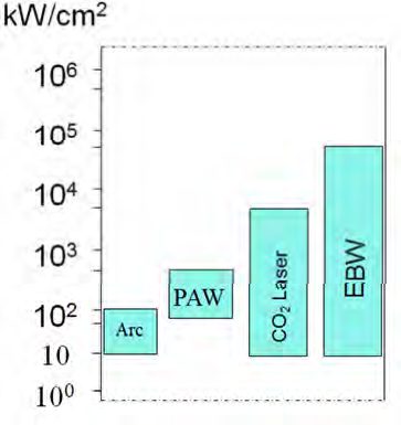
Figure 2: Power densities of various welding processes.
High energy density processes produce weld profiles of high depth-to-width ratio, as compared to other welding processes (Figure 3). As a result, much greater thicknesses can be welded in a single pass, especially with EBW. The figure also illustrates the fact that high energy density processes can produce a weld with minimal heating to the surrounding area as compared to the other processes. However, the high depth-to-width ratio weld profile is much less forgiving to imperfect joint fit-up than the profile produced by arc welding processes.
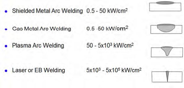
Figure 3: Comparison of typical weld profiles.
Laser and EBW processes are used in a wide variety of industry sectors. Very high weld speeds are possible and the welds are usually aesthetically pleasing. Laser welding is very adaptable to high-speed production so it is common in the automotive sector. The ability to precisely locate welds on smaller sensitive components with minimal heat input makes laser welding very attractive to the medical products industry.
When welding with high energy density processes, the laser or EB is focused along the joint line of the workpieces to be welded. The extreme power density of the beam not only melts the material, but causes evaporation. As the metal atoms evaporate, forces in the opposite direction create a significant localized vapor pressure. This pressure creates a hole, known as a keyhole, by depressing the free surface of the melted metal. The weld solidifies behind the keyhole as it progresses along the joint (Figure 4). This method of welding known as keyhole welding is the most common approach to laser and EB, and produces the characteristic welds of high depth-to-width ratio. There are some cases where the keyhole mode is not used. This mode is known as conductive mode welding. Conductive mode welds have a weld profile closer to that of an arc weld A-11, P-6
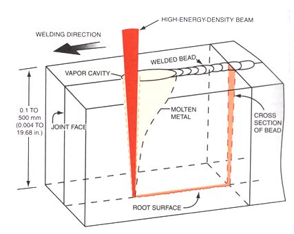
Figure 4: Keyhole mode welding.