This article explores the challenges of liquid metal embrittlement (LME) in resistance spot welding (RSW) of automotive components, particularly focusing on a component-scale S-Rail made from advanced high-strength steel (AHSS). The study aims to identify the occurrence of LME during the welding process and to propose effective strategies for its mitigation. This article is an excerpt from the “LME component study” conducted by WorldAutoSteel. The full study can be downloaded here.
Experimental and Simulative Setup
The experiments utilized an electrogalvanized RA1180 AHSS joined to hot-dip galvanized mild steel. Two stack-up configurations were tested: similar (both sheets made of RA1180) and dissimilar (RA1180 on top of mild steel). The resistance spot welding process was monitored using sensors to record current, voltage, and force. Different welding parameters, such as hold time and electrode geometry, were varied to observe their effects on LME.
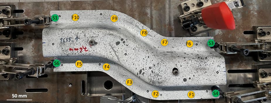
Figure 1: Top-view of the S-Rail component during welding. The clamping points S1-S4 as well as the welding points F1-F10 are highlighted.
A simulation-based risk criterion for LME was established based on local stresses in the components. Both experimental and numerical analyses were conducted to assess the influence of various parameters on LME formation. Specifically, the study evaluated how springback, a phenomenon occurring during deep drawing, affects LME risk. Correct clamping can effectively suppress springback, consequently reducing LME occurrences.
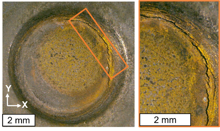
Figure 2: Experimentally observed cracks with 5° tilted electrodes and doubled welding time of 760 ms.
Findings
- Influence of Springback: Springback contributed to LME formation. When clamping was employed to counteract springback, LME was effectively eliminated from the welded samples.
- Electrode Geometry and Hold Time: Adjustments to the electrode geometry and increasing hold time after welding further mitigated LME risks. Specifically, larger electrode tip diameters and longer hold times reduced the likelihood of cracks.
- Material Stack-up Effects: The experiments indicated that the configuration of the material stack-up influenced LME occurrences. Only stack-ups with thick joining partners showed occurrence of LME in the trials.
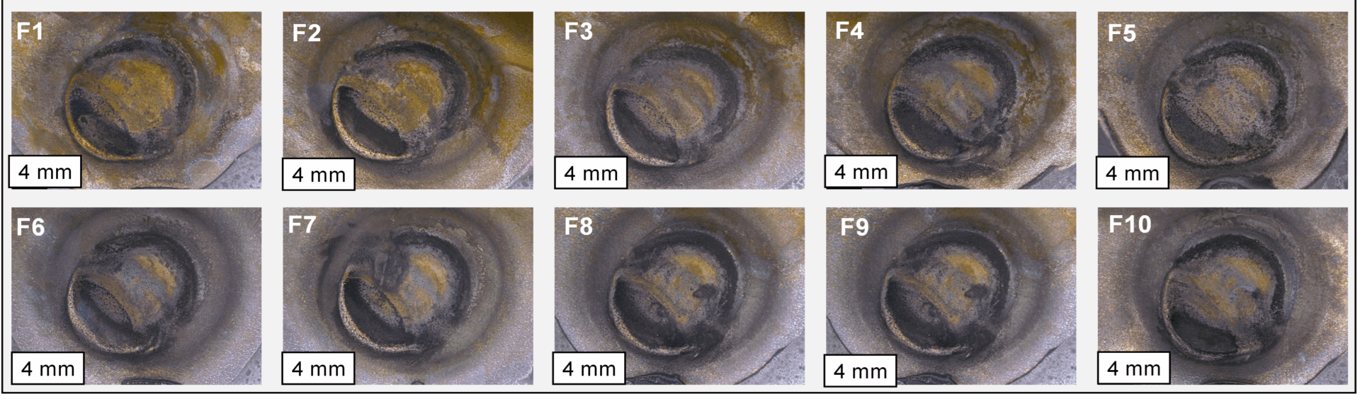
Figure 3: All 10 resistance spot welds on the S-rail are crack-free after optimizing either springback, electrode working plane diameter or post-weld hold time
Simulation Results
Finite element simulations were used to evaluate the risk of LME by analyzing local stresses and temperature distributions during welding. The results showed that the springback-affected samples presented a higher LME risk compared to idealized, straightened models. This finding aligns with experimental observations that cracks occurred where excessive springback influenced the welding process. Even in the case of springback, LME could be effectively prevented by using electrode caps with larger working planes as well as slightly extending the hold time after welding.
The developed simulation approach allows comparing the LME conditions for different welding setups and can therefore optimize the LME occurrence for geometry, material and welding conditions.
Conclusion
Effective mitigation strategies, such as clamping to suppress springback and adjustments in welding parameters, can prevent LME on a component-scale. It can also be highlighted that today’s AHSS grades are far less sensitive to LME by-default so that few RSW joints in a whole body-in-white are at all susceptible for cracking: To produce cracks for this study, welding parameters with increased energy input had to be used; no LME was observed under “standard” industrial conditions.
homepage-featured-top, main-blog
In this edition of AHSS Insights, George Coates and Menachem Kimchi get back to basics with important fundamentals in forming and joining AHSS.
As the global steel industry continues its development of Advanced High-Strength Steels (AHSS), including 3rd Gen products with enhanced formability, we’re reminded that successful application is still dependent on the fundamentals, both in forming and joining. In this blog article, we address some of those forming considerations, as well as highlighting common joining issues in manufacturing.
Forming Considerations
The somewhat lower formability of AHSS compared to mild steels can almost always be compensated for by modifying the design of the component and optimizing blank shape and the forming process.
In stamping plants, we’ve observed inconsistent practices in die set-up and maintenance, surface treatments and lubrication application. Some of these inconsistencies can be addressed through education, via training programs on AHSS Application Guidelines. These Guidelines share best practices and lessons learned to inform new users on different behaviors of specific AHSS products, and the necessary modifications to assist their application success. In addition to new practices, we’ve learned that applying process control fundamentals become more critical as one transitions from mild steels to AHSS, because the forming windows are smaller and less forgiving, meaning these processes don’t tolerate variation well. If your present die shop is reflective of housekeeping issues, such as oil and die scrap on the floor or die beds, you are a candidate for a shop floor renovation or you will struggle forming AHSS products.
Each stamping operation combines three main elements to achieve a part meeting its desired functional requirements:
There is good news, in that our industry is responding with new products and services to improve manufacturing performance and save costs.
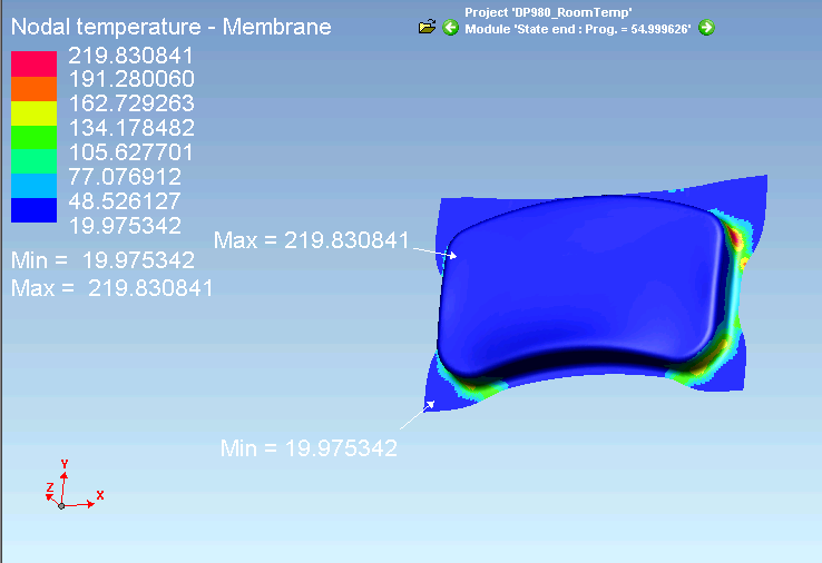
As an example, lubrication application is often overlooked, and old systems may be ineffective. In the forming of AHSS, part temperatures can become excessive, and break down lubricant performance. Figure 1 shows an example of part temperatures from an Ohio State University study conducted with DP 980 steels.O-1
Figure 1: Example Temperature distribution for DP 980 Steel.O-1
Stampers often respond by “flooding” the process with extra lubricant, thinking this will solve their problem. Instead, lubricant viscosity and high temperature stability are the most important considerations in the lubricant selection, and new types exist to meet these challenges. Also, today there are new lubrication controllers that can finely control and disperse wet lubricants evenly across the steel strip, or in very specific locations, if forming requirements are localized. These enable better performance while minimizing lubricant waste (saving cost), a win-win for the pressroom.
Similarly, AHSS places higher demands on tool steels used in forming and cutting operations. In forming applications, galling, adhesive wear and plastic deformation are the most common failure mechanisms. Surface treatments such as PVD, CVD and TD coatings applied to the forming tool are effective at preventing galling. Selection of the tool steel and coating process used for forming AHSS will largely depend on the:
- Strength and thickness of the AHSS product,
- Steel coating,
- Complexity of the forming process, and
- Number of parts to be produced.
New die materials such as “enhanced D2” are available from many suppliers. These improve the balance between toughness, hardness and wear resistance for longer life. These materials can be thru-hardened, and thus become an excellent base material for PVD or secondary surface treatments necessary in the AHSS processing. And new tool steels have been developed specifically for hot forming applications.
Joining Considerations
In high-volume production different Resistance Spot Welding (RSW) process parameters can be used depending on the application and the specifications applied. Assuming you chose the appropriate welding parameters that allows for a large process window, manufacturing variables may ruin your operation as they strongly effect the RSW weld quality and performance.
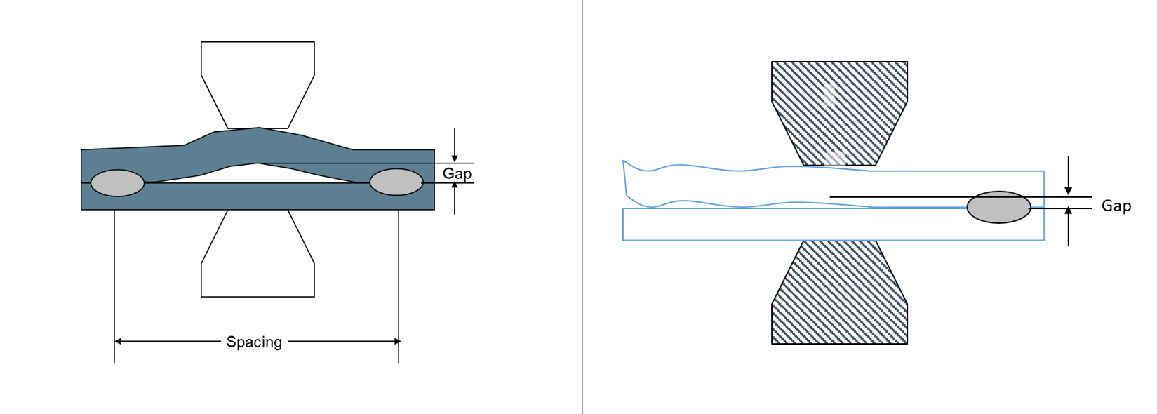
Material fit-up
One of the great advantages of the RSW process is the action of clamping the material together via the electrode force applied during the process. However due to the pre-welding condition/processing such as the stamping operation, this fit-up issue, as shown in Figure 2, can be very significant especially in welding an AHSS product. In this case the effective required force specified during the process setup for the application is significantly reduced and can result in an unacceptable weld, over-heating, and severe metal expulsion. If the steels are coated, higher probability for Liquid Metal Embrittlement (LME) cracking is possible.

Figure 2: Examples of Pre-Welding Condition/Processing Fit-Up Issues.
For welding AHSS, higher forces are generally required as a large part of the force is being used to force the parts together in addition to the force required for welding. Also, welding parameters may be set for pre-heating with lower current pulses or current up-slope to soften the material for easier material forming and to close the gap.
Electrodes Misalignment
During machine set up, the RSW electrodes need to be carefully aligned as shown in Figure 3A. However, in many production applications, electrode misalignment is a common problem.
Electrode misalignment in the configurations shown in Figure 3B may be detrimental to weld quality of any RSW application. Of course, the electrode misalignment shown in this figure is exaggerated but the point is that it happens frequently on manufacturing welding lines.
In these cases, the intendent contact between the electrodes is not achieved and thus the current density and the force density (pressure) required for producing an acceptable weld cannot be achieved. With such conditions, overheating, expulsion, sub-size welds and extensive electrode wear will result. Again, if coated steels are involved, the probability for LME cracking is higher.
Note also that following specifications or recommendations for water cooling the electrode is always important for process stability and extending electrode life.
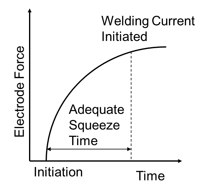
Figure 4: Sequence of Squeeze Time and Welding Current Initiation.
Squeeze Time
The squeeze time is the time required for the force to reach the level needed for the specific application. Welding current should be applied only after reaching this force, as indicated in Figure 4. All RSW controllers enable the easy control of squeeze time, just as with the weld time, for example. In many production operations, a squeeze time is used that is too low due to lack of understanding of its function. If squeeze time is too low, high variability in weld quality in addition to severe expulsion will be the result.
The squeeze time required for an application depends on the machine type and characteristics (not an actual welding parameter such as weld time or welding current for example).
Some of the more modern force gauges have the capability to produce the curve shown in the Figure so adequate squeeze time will be used. If you do not know what the required squeeze time for your machine/application is, it is recommended to use a longer time.
For more on these topics, browse the Forming and Joining menus of these Guidelines.