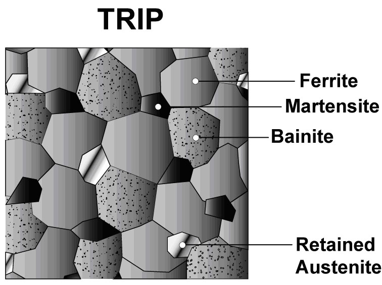
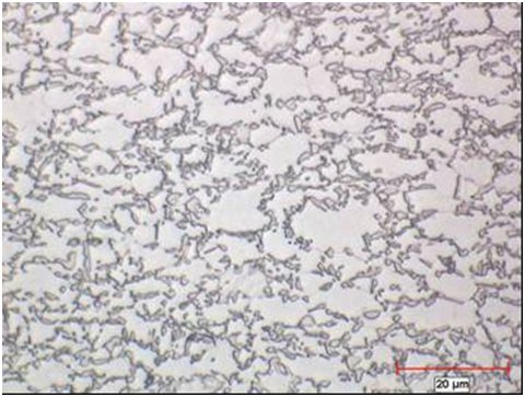
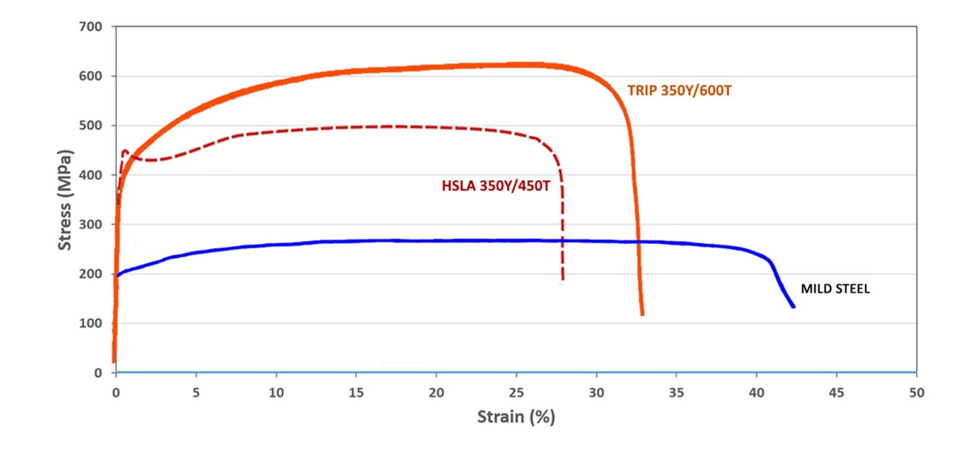
The microstructure of Transformation Induced Plasticity (TRIP) steels contains a matrix of ferrite, with retained austenite, martensite, and bainite present in varying amounts. Production of TRIP steels typically requires the use of an isothermal hold at an intermediate temperature, which produces some bainite. Higher silicon and carbon content of TRIP steels result in significant volume fractions of retained austenite in the final microstructure. Figure 1 shows a schematic of TRIP steel microstructure, with Figure 2 showing a micrograph of an actual sample of TRIP steel. Figure 3 compares the engineering stress-strain curve for HSLA steel to a TRIP steel curve of similar yield strength.
Figure 1: Schematic of a TRIP steel microstructure showing a matrix of ferrite, with martensite, bainite and retained austenite as the additional phases.
Figure 2: Micrograph of Transformation Induced Plasticity steel.
Figure 3: A comparison of stress strain curves for mild steel, HSLA 350/450, and TRIP 350/600.K-1
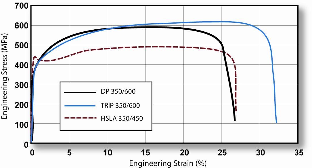
During deformation, the dispersion of hard second phases in soft ferrite creates a high work hardening rate, as observed in the DP steels. However, in TRIP steels the retained austenite also progressively transforms to martensite with increasing strain, thereby increasing the work hardening rate at higher strain levels. This is known as the TRIP Effect. This is illustrated in Figure 4, which compares the engineering stress-strain behavior of HSLA, DP and TRIP steels of nominally the same yield strength. The TRIP steel has a lower initial work hardening rate than the DP steel, but the hardening rate persists at higher strains where work hardening of the DP begins to diminish. Additional engineering and true stress-strain curves for TRIP steel grades are shown in Figure 5.
Figure 4: TRIP 350/600 with a greater total elongation than DP 350/600 and HSLA 350/450. K-1
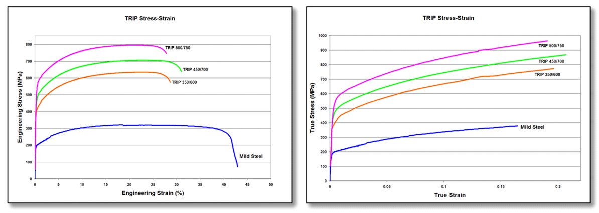
Figure 5: Engineering stress-strain (left graphic) and true stress-strain (right graphic) curves for a series of TRIP steel grades. Sheet thickness: TRIP 350/600 = 1.2mm, TRIP 450/700 = 1.5mm, TRIP 500/750 = 2.0mm, and Mild Steel = approx. 1.9mm. V-1
The strain hardening response of TRIP steels are substantially higher than for conventional HSS, resulting in significantly improved formability in stretch deformation. This response is indicated by a comparison of the n-value for the grades. The improvement in stretch formability is particularly useful when designers take advantage of the improved strain hardening response to design a part utilizing the as-formed mechanical properties. High n-value persists to higher strains in TRIP steels, providing a slight advantage over DP in the most severe stretch forming applications.
Austenite is a higher temperature phase and is not stable at room temperature under equilibrium conditions. Along with a specific thermal cycle, carbon content greater than that used in DP steels are needed in TRIP steels to promote room-temperature stabilization of austenite. Retained austenite is the term given to the austenitic phase that is stable at room temperature.
Higher contents of silicon and/or aluminum accelerate the ferrite/bainite formation. These elements assist in maintaining the necessary carbon content within the retained austenite. Suppressing the carbide precipitation during bainitic transformation appears to be crucial for TRIP steels. Silicon and aluminum are used to avoid carbide precipitation in the bainite region.
The carbon level of the TRIP alloy alters the strain level at which the TRIP Effect occurs. The strain level at which retained austenite begins to transform to martensite is controlled by adjusting the carbon content. At lower carbon levels, retained austenite begins to transform almost immediately upon deformation, increasing the work hardening rate and formability during the stamping process. At higher carbon contents, retained austenite is more stable and begins to transform only at strain levels beyond those produced during forming. At these carbon levels, retained austenite transforms to martensite during subsequent deformation, such as a crash event.
TRIP steels therefore can be engineered to provide excellent formability for manufacturing complex AHSS parts or to exhibit high strain hardening during crash deformation resulting in excellent crash energy absorption.
The additional alloying requirements of TRIP steels degrade their resistance spot-welding behavior. This can be addressed through weld cycle modification, such as the use of pulsating welding or dilution welding. Table 1 provides a list of current production grades of TRIP steels and example automotive applications:
Table 1: Current Production Grades Of TRIP Steels And Example Automotive Applications.
Some of the specifications describing uncoated cold rolled 1st Generation transformation induced plasticity (TRIP) steel are included below, with the grades typically listed in order of increasing minimum tensile strength and ductility. Different specifications may exist which describe hot or cold rolled, uncoated or coated, or steels of different strengths. Many automakers have proprietary specifications which encompass their requirements.
• ASTM A1088, with the terms Transformation induced plasticity (TRIP) steel Grades 690T/410Y and 780T/440YA-22
• JFS A2001, with the terms JSC590T and JSC780TJ-23
• EN 10338, with the terms HCT690T and HCT780TD-18
• VDA 239-100, with the terms CR400Y690T-TR and CR450Y780T-TRV-3
• SAE J2745, with terms Transformation Induced Plasticity (TRIP) 590T/380Y, 690T/400Y, and 780T/420YS-18
Transformation Induced Plasticity Effect
Austenite is not stable at room temperature under equilibrium conditions. An austenitic microstructure is retained at room temperature with the combined use of a specific chemistry and controlled thermal cycle.
Deformation from sheet forming or from crash impact provides the necessary energy to allow the crystallographic structure to change from austenite to martensite. There is insufficient time and temperature for substantial diffusion of carbon to occur from carbon-rich austenite, which results in a high-carbon (high strength) martensite after transformation. Strengthening also occurs from the dislocations formed in the adjacent ferrite required to accommodate the volume increase associated with the austenite-to-martensite transformation.
Transformation to high strength martensite continues as deformation increases, as long as retained austenite (RA) is still available to be transformed. Optimal combinations of strength and ductility are obtained when the retained austenite stability is such that the transformation to martensite occurs gradually with increasing strain.
In these grades, increasing the stability of the retained austenite phase delays the austenite-to-martensite transformation to higher strain levels, further promoting formability improvements.
Several factors may promote higher RA stability, including additions of carbon (C) and manganese (Mn). Smaller austenite grains lower the martensite start temperature (Ms) and the number of martensite nucleation sites in each grain, and as such more energy (strain) is needed to start the transformation.
Additions of silicon (Si), chromium (Cr), and aluminum (Al) are also beneficial to achieving the TRIP effect since each of these elements suppress cementite (iron carbide, Fe3C) formation and thereby allows for carbon enrichment of austenite.
However, Mn, Si, Cr, and Al all form oxides on the steel surface that hinder galvanizing and paintability associated with the e-coat layer. Steelmakers typically choose an alloy development and processing strategy which minimizes the detrimental effects of these oxides.
Temperature also has an effect, not only from the paint-bake temperatures of approximately 170 °C, but from galvanizing at close to 500 °C. Citation Z-20 studied the effects of temperature on 0.1%C-5%Mn Medium Manganese steels and found that while tensile strength was relatively independent with temperature, ductility slightly decreases as the temperature is raised from room temperature to 400 °C, but drops off substantially by 500 °C. To retain the formability benefits associated with RA grades, the article recommends galvanizing at temperatures below 400 °C.
In addition to the paint-bake and galvanizing temperatures, adiabatic heating from forming (including shearing and stamping) impact properties. The temperature during forming can be influenced by the starting ambient temperature, the plastic energy dissipation, the latent heat of transformation and by conduction and convection to the environment.M-76
While deforming a metal, most of the energy is dissipated in the form of heat while only a small amount is stored. Austenite-to-martensite transformation kinetics are highly influenced by temperature, and the heating effects associated with mechanically-induced transformation can lead to a severe reduction in ductility.
The temperature rise due to dissipation is not negligible and since the TRIP effect is extremely sensitive to temperature, there is a need for a model to predict this behavior well. Such a model is described in Citation M-76, which reviews that retained austenite stability is a function of several parameters such as temperature; carbon content and alloying elements; austenite grain size and morphology; austenite grain orientation and distribution within the microstructure; and hydrostatic pressure.
Complex Phase (CP) steels combine high strength with relatively high ductility. The microstructure of CP steels contains small amounts of martensite, retained austenite and pearlite within a ferrite/bainite matrix. A thermal cycle that retards recrystallization and promotes Titanium (Ti), Vanadium (V), or Niobium (Nb) carbo-nitrides precipitation results in extreme grain refinement. Minimizing retained austenite helps improve local formability, since forming steels with retained austenite induces the TRIP effectproducing hard martensite.F-11
The balance of phases, and therefore the properties, results from the thermal cycle, which itself is a function of whether the product is hot rolled, cold rolled, or produced using a hot dip process. CitationP-18indicates that galvannealed CP steels are characterized by low yield value and high ductility, whereas cold rolled CP steels are characterized by high yield value and good bendability. Typically these approaches require different melt chemistry, potentially resulting in different welding behavior.
CP steel microstructure is shown schematically in Figure 1, with the grain structure for hot rolled CP 800/1000 shown in Figure 2. The engineering stress-strain curves for mild steel, HSLA steel, and CP 1000/1200 steel are compared in Figure 3.
Figure 1: Schematic of a complex phase steel microstructure showing martensite and retained austenite in a ferrite-bainite matrix.
Figure 2: Micrograph of complex phase steel, HR800Y980T-CP.C-14
Figure 3: A comparison of stress strain curves for mild steel, HSLA 350/450, and CP 1000/1200.
DP and TRIP steels do not rely on precipitation hardening for strengthening, and as a result, the ferrite in these steels is relatively soft and ductile. In CP steels, carbo-nitride precipitation increases the ferrite strength. For this reason, CP steels show significantly higher yield strengths than DP steels at equal tensile strengths of 800 MPa and greater. Engineering and true stress-strain curves for CP steel grades are shown in Figure 4.
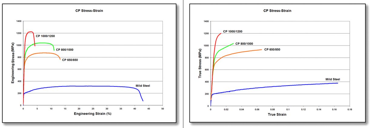
Figure 4: Engineering stress-strain (left graphic) and true stress-strain (right graphic) curves for a series of CP steel grades. Sheet thickness: CP650/850 = 1.5mm, CP 800/1000 = 0.8mm, CP 1000/1200 = 1.0mm, and Mild Steel = approx. 1.9mm.V-1
Table 1 compares galvannealed Dual Phase and Complex Phase steels having similar tensile strength and elongation as measured in a tensile test. The characteristics with the biggest difference are the yield strength and the hole expansion ratio which is a measure of cut-edge stretchability.
In the VDA-238 bending test, 980 DP exhibited a significant fracture with a bending angle of 67°. The 980 CP showed no fracture at 80°, and was capable of bending to over 100° before fracturing, Figure 5.N-33 The galvannealed 980 CP suppressed crack generation in axial crushing deformation to a much greater degree than the 980 DP.
Figure 5. Bendability of 980 DP (sample A) and 980 CP (sample B).N-33
Examples of typical automotive applications benefitting from these high strength steels with good local formabilityinclude frame rails, frame rail and pillar reinforcements, transverse beams, fender and bumper beams, rocker panels, and tunnel stiffeners.
Some of the specifications describing uncoated cold rolled 1st Generation complex phase (CP) steel are included below, with the grades typically listed in order of increasing minimum tensile strength and ductility. Different specifications may exist which describe hot or cold rolled, uncoated or coated, or steels of different strengths. Many automakers have proprietary specifications which encompass their requirements.
ASTM A1088, with the terms Complex phase (CP) steel Grades 600T/350Y, 780T/500Y, and 980T/700Y A-22
EN 10338, with the terms HCT600C, HCT780C, and HCT980C D-18
VDA239-100, with the terms CR570Y780T-CP,CR780Y980T-CP, and CR900Y1180T-CPV-3
Ferrite-Bainite (FB) steels are hot rolled steels typically found in applications requiring improved edge stretch capability, balancing strength and formability. The microstructure of FB steels contains the phases ferrite and bainite. High elongation is associated with ferrite, and bainite is associated with good edge stretchability. A fine grain size with a minimized hardness differences between the phases further enhance hole expansion performance. These microstructural characteristics also leads to improved fatigue strength relative to the tensile strength.
FB steels have a fine microstructure of ferrite and bainite. Strengthening comes from by both grain refinement and second phase hardening with bainite. Relatively low hardness differences within a fine microstructure promotes good Stretch Flangable (SF) and high hole expansion (HHE) performance, both measures of local formability. Figure 1 shows a schematic Ferrite-Bainite steel microstructure, with a micrograph of FB 400Y540T shown in Figure 2.
Figure 2: Micrograph of Ferrite-Bainite steel, HR400Y540T-FB.H-21
The primary advantage of FB steels over HSLA and DP steels is the improved stretchability of sheared edges as measured by the hole expansion test. Compared to HSLA steels with the same level of strength, FB steels also have a higher strain hardening exponent (n-value) and increased total elongation. Figure 3 compares FB 450/600 with HSLA 350/450 steel. Engineering and true stress-strain curves for FB steel grades are shown in Figure 4.
Figure 3: A comparison of stress strain curves for mild steel, HSLA 350/450, and FB 450/600.
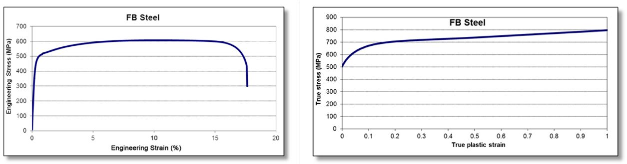
Figure 4: Engineering stress-strain (left graphic) and true stress-strain (right graphic) curve for FB 450/600.T-10
Examples of typical automotive applications benefitting from these high strength highly formable grades include automotive chassis and suspension parts such as upper and lower control arms, longitudinal beams, seat cross members, rear twist beams, engine sub-frames and wheels.
Some of the specifications describing uncoated hot rolled 1st Generation ferrite-bainite (FB) steel are included below, with the grades typically listed in order of increasing minimum tensile strengthand ductility. Different specifications may exist which describe uncoated or coated versions of these grades. Many automakers have proprietary specifications which encompass their requirements.
First Generation Advanced High-Strength Steels (AHSS) are based on a ferrite matrix for baseline ductility, with varying amounts of other microstructural components like martensite, bainite, and retained austenite providing strength and additional ductility. These grades have enhanced global formability compared with conventional high strength steels at the same strength level. However, local formability challenges may arise in some applications due to wide hardness differences between the microstructural components.
The Second Generation AHSS grades have essentially a fully austenitic microstructure and rely on a twinning deformation mechanism for strength and ductility. Austenitic stainless steels have similar characteristics, so they are sometimes grouped in this category as well. 2nd Gen AHSS grades are typically higher-cost grades due to the complex mill processing to produce them as well as being highly alloyed, the latter of which leads to welding challenges.
Third Generation (or 3rd Gen) AHSS are multi-phase steels engineered to develop enhanced formability as measured in tensile, sheared edge, and/or bending tests. Typically, these steels rely on retained austenite in a bainite or martensite matrix and potentially some amount of ferrite and/or precipitates, all in specific proportions and distributions, to develop these enhanced properties.
Individual automakers may have proprietary definitions of 3rd Gen AHSS grades containing minimum levels of strength and ductility, or specific balances of microstructural components. However, such globally accepted standards do not exist. Prior to 2010, one steelmaker had limited production runs of a product reaching 18% elongation at 1000 MPa tensile strength. Starting around 2010, several international consortia formed with the hopes of achieving the next-level properties associated with 3rd Gen steels in a production environment. One effortU-11, S-95 targeted the development of two products: a high strength grade having 25% elongation and 1500 MPa tensile strength and a high ductility grade targeting 30% elongation at 1200 MPa tensile strength. The “exceptional-strength/high-ductility” steel achieved 1538 MPa tensile strength and 19% elongation with a 3% manganese steel processed with a QP cycle. The 1200 MPa target of the “exceptional-ductility/high-strength” was met with a 10% Mn alloy, and exceeded the ductility target by achieving 37% elongation. Another effort based in EuropeR-22 produced many alloys with the QP process, including one which reached 1943 MPa tensile strength with 8% elongation. Higher ductility was possible, at the expense of lower strength.
3rd Gen steels have improved ductility in cold forming operations compared with other steels at the same strength level. As such, they may offer a cold forming alternative to press hardening steels in some applications. Also, while 3rd Gen steels are intended for cold forming, some are appropriate for the hot stamping process.
Like all steel products, 3rd Gen properties are a function of the chemistry and mill processing conditions. There is no one unique way to reach the properties associated with 3rd Gen steels – steelmakers use their available production equipment with different characteristics, constraints, and control capabilities. Even when attempting to meet the same OEM specification, steelmakers will take different routes to achieve those requirements. This may lead to each approved supplier having properties which fall into different portions of the allowable range. Manufacturers should use caution when switching between suppliers, since dies and processes tuned for one set of properties may not behave the same when switching to another set, even when both meet the OEM specification.
There are three general types of 3rd Gen steels currently available or under evaluation. All rely on the TRIP effect. Applying the QP process to the other grades below may create additional high-performance grades.
TRIP-Assisted Bainitic Ferrite (TBF) and Carbide-Free Bainite (CFB) are descriptions of essentially the same grade. Some organizations group Dual Phase – High Ductility (DP-HD, or DH) in with these. Their production approach leads to an ultra-fine bainitic ferrite grain size, resulting in higher strength. The austenite in the microstructure allows for a transformation induced plasticity effect leading to enhanced ductility.
Quenching and Partitioning (Q&P) describes the processing route resulting in a structure containing martensite as well as significant amounts of retained austenite. The quenching temperature helps define the relative percentages of martensite and austenite while the partitioning temperature promotes an increased percentage of austenite stabile room temperature after cooling.
Medium Manganese steels have a Mn content of approximately 3% to 12%, along with silicon, aluminum, and microalloying additions. This alloying approach allows for austenite to be stable at room temperature, leading to the TRIP Effect for enhanced ductility during stamping. These grades are not yet widely commercialized.
TRIP Assisted Grades, like TRIP-Assisted Bainitic Ferrite (TBF)
and Carbide-Free Bainite (CFB)
During the slow cooling of conventional steels, austenite transforms into a microstructure containing alternating regions of ferrite and cementite. Note that cementite is the name given to iron carbide with the composition Fe3C. At higher magnification, this microstructure looks like Mother-of-Pearl, leading to its name of pearlite.
Depending on the chemistry and thermal profile, rapid controlled cooling produces new microstructures which are not achievable with slow cooling, including martensite, austenite, and bainite. Bainite consists of regions of dislocation-rich (higher strength) ferrite separated by austenite, martensite, and/or cementite. These phases within bainite have relatively small hardness differences, leading to improved local formability compared with conventional dual phase or TRIP steels. Producing a fully-bainitic microstructure is challenging, so bainite is usually accompanied by other phases, resulting in ferrite-bainite steels or complex phase.
With an appropriate chemistry and use of specific thermal profiles capable of holding at specific temperatures and even reheating after quenching further reduces the size of these microstructural components, and essentially eliminates the production of the low-ductility cementite (iron carbide). Large “blocky” austenite, characteristic of 1st Generation TRIP steels, is minimized and instead thin fine submicron austenitic laths form (Figure 1).
Figure 1: On the left, the typical bainitic structure showing bainitic ferrite laths with interlath carbideS-96; On the right is the microstructure of TRIP Assisted Bainitic Ferrite / Carbide Free Bainite showing bainitic ferrite laths interwoven with thin films of untransformed retained austenite.C-31 αb is bainitic ferrite and γ is retained austenite. Note the slightly different magnification.
The fine components result in higher strength, similar to fine grain size being associated with increased strength. Since the ferrite is higher strength than conventional bainite due to the fine component size and even greater dislocation density, the component hardness difference is further minimized, leading to additional improvements in local formability. The austenite promotes the TRIP effect, resulting in greater uniform elongation and enhanced global formability. Combined, these features result in calling this microstructure either TRIP Assisted Bainitic Ferrite (TBF) or Carbide Free Bainite (CFB). Some sources suggest this is the same product as “Dual Phase with High Ductility,” abbreviated as DP-HD or simply DH.H-18, A-70, R-23, B-58 TBF, CFB, DP-HD, and DH are used interchangeably.
Examples of parts made from DH steels are found in Figure 2. The retained austenite in the microstructure improves the edge ductility and bendability, making these parts feasible.
Figure 2: Parts made from DH steels. Crossmember component (CR330/590DH, top image), Seat crossmember (CR440/780DH, middle image), and Crossmember Front Floor (CR550/980DH, bottom image).
One potential processing route (Figure 3) may involve intercritical annealing in the two-phase austenite+ferrite region, cooling slightly to promote ferrite formation (1→2), and then quenching (2→3) to a temperature below the start of bainite formation (Bs) while remaining above the Ms temperature, the start of martensitic transformation. Once the targeted amount of bainite has formed in an isothermal overaging step (3→4), the steel is then quenched to room temperature (4→5).
Figure 3: Potential thermal cycle to produce TRIP assisted Bainitic Ferrite (Carbide-Free Bainite).
These steels are characterized by a good balance of strength and global formability (as measured by high TSxEL, uniform elongation, and total elongation combined with low YS/TS) against local formability (as measured by bend angle and hole expansion ratio).C-31 A YS/TS ratio of approximately 0.7, similar to DP steels, is a characteristic of these grades.H-59,C-31
These steels exhibit a significant bake hardening response. One study found a BH kick of over 200 MPa after a 4% prestrain and a bake cycle of 30 minutes at 200 °C. The total hardening response (strain hardening plus bake hardening) was almost 800 MPa.T-41 However, in production, this paint bake cycle is not likely to be practical due to paint over curing and the preference for faster cycle times. A different study evaluated TBF700Y/1050T and found after 15 minutes at 195 °C, samples prestrained to 4.5% had a BH kick of 150 MPa, with a total hardening response in excess of 350 MPa.B-60
Challenges exist when producing these grades with a galvanized or galvannealed coating. The relatively higher silicon content needed to suppress carbide formation may lead to difficulties galvanizing and with galvanized surface quality. Replacing silicon with aluminum helps with the coating issues, but makes the thermal cycle more complex. The chosen thermal cycle needs to be appropriate for the selected chemistry and targeted properties, and constrained by the capabilities of the existing mill equipment. Descriptions of the capabilities of equipment used in the production of cold rolled and galvanized AHSS are found elsewhere.K-43, B-59
The 2013 Infiniti Q50 is one of the earliest production applications for TBF 1180, where it formed 4% of the Body-In-White mass. Applications included A- and B-pillar reinforcements, sill reinforcements, and roof rail and side reinforcements. Adjusted welding techniques resulted in the same stress concentration as seen when welding mild steels.I-22, K-44 The same grade applied on the 2015 Nissan Murano in the A-Pillar Inner and reinforcements allowed numerous components to be downgauged from 1.6 mm to 1.2 mm compared with the prior version.C-32 1180TBF represented over 6% of the mass of the 2016 Nissan Maxima body-in-white, primarily applied in the A- and B-Pillar Reinforcements. Typically, 1.4 mm thick 980 grade steel was downgauged to 1.2 mm.C-33
A sample of commercially available TBF1180 was shown to have 946 MPa yield strength, 1222 MPa tensile strength, 18% elongation (JIS sample) , with a 40% hole expansion ratioM-54, which is consistent with the minimum properties listed by one automotive OEM: YS: 850 MPa minimum, TS: 1180 MPa minimum, elongation: 14% JIS minimum, and 30% minimum hole expansion ratio.F-36 Stretch formability as tested using a dome height evaluation was shown to be comparable to a conventional DP980 product, with deep drawability characterized by forming height in a cup draw test being superior to both conventional DP980 and DP1180.
Stress-strain curves of TBF700Y/1050T are found in the literature and presented in Figure 4 for reference. Note that these are random samples from a commercially available product tested at different laboratories, and therefore may not be representative of all products of this grade.
Figure 4: Stress strain curves of commercially available TBF 700Y/1050T. A) YS=775 MPa, TS = 1235 MPa, EL = 10%G-44; B) YS=751 MPa, TS = 1035 MPa, EL = 17%. Also shown is the pre-strain and bake hardening response for 1.0 mm thick blanks, tested after a 20 minute dwell time in a 170 °C furnace.B-60
The 2018 Infiniti QX50 SUV is an example of a vehicle believed to have TBF980 in the body structure.I-23 The product shown is called SHF980, and has a microstructure of approximately 50% ferrite, approximately 10% retained austenite, with the remainder as martensite/bainite, which is consistent with expectations for a TBF product. The thermal processing route to achieve this microstructural balance is consistent with a Quenching & Partitioning process (Figure 5). Both SHF980 and the reference DP980 are shown to have 660 MPa yield strength and 1000 MPa tensile strength. However, where DP980 has 15% elongation, SHF980 has 23% elongation. In addition, SHF980 is capable of 10% greater energy absorption over DP980 at the same thickness.I-23
Figure 5: Production and properties of SHF980, possessing a TBF microstructure.I-23
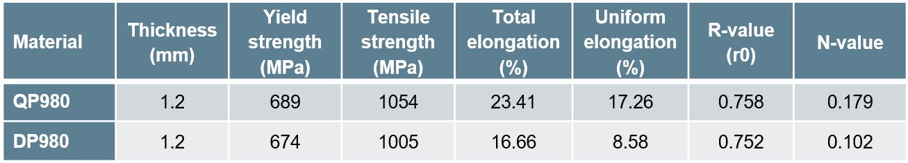
The highest strength TBF grade commercially available has 1,470MPa minimum tensile strength. Properties in Table 1 are compared with DP1470.
Table 1: Tensile properties of 1.2mm steels with 1470 MPa minimum tensile strength.M-55
Case Study: Production Application Where 3rd Gen Steels
Reduced Weight and Improved Performance
Toyota Motor Europe designed a part requiring a minimum tensile strength of 980 MPa, but when stamped using a conventional AHSS grade, experienced both global formability (necking) failures and local formability (sheared edge) failures (Figure 6). In the search for a grade which blended the high elongation of dual phase grades and the high hole expansion of complex phase grades, Toyota chose TBF980, a TRIP-assisted bainitic ferrite grade with the same yield and tensile strength of a conventional 980 grade but with improved elongation of approximately 14% and hole expansion of approximately 65%.A-1
Also reported were grade and design changes in a production vehicle where the strength of TBF980 allows for a 20% thickness reduction over the prior model. The improved formability of TBF980 facilitated a reduction in packaging space of the component, with the new design being 6% narrower and 20% shorter. Combined, these improvements reduced the vehicle weight by 1 kg.A-1
Figure 6: 980 MPa part with global and local formability failures. Converting the steel to TBF980 eliminated both types of splits. Image adapted from Citation A-1.
Quenched and Partitioned Grades, Q&P or simply QP
Quenching and partitioning (Q&P, or QP) describes a multi-step heat treatment which produces high tensile strength, high global ductility (total elongation) and high local ductility (hole expansion and bendability), compared with other similar strength steels. The QP process was first explained in 2003 by Speer et al.S-97, S-98, S-99
Among the unique aspects of the required thermal cycle is that after the first quench from the fully austenitized or intercritical annealing temperature, the steel may be reheated to a higher temperature, and then quenched to room temperature.
Figure 7 provides a general overview of the QP thermal cycle. After austenitization in either the single phase austenite region or the two-phase ferrite+austentite (intercritical annealing), the steel is quenched to a temperature below the start of martensitic transformation (Ms) but above the Mf (temperature at which all austenite has transformed to martensite), as indicated by segment 1→2. In the two-step QP process, the temperature is raised above Ms, shown in segment 2→3. No temperature increase is seen in the one-step QP process, meaning 2=3. Then the steel is held at this partitioning temperature for the appropriate time to generate the targeted microstructure and properties, segment 3→4. Once reached, the steel is quenched again (4→5), this time to a temperature below Mf, the temperature below which all transformation to martensite has occurred.
Figure 7: Thermal cycle for the Quenching and Partitioning Process.
The QP microstructure contains martensite and austenite. Ferrite is also present if intercritical annealing in the two-phase region is employed rather than in the single-phase austenitic region. The first quench forms a controlled volume fraction of martensite. With a QP chemistry containing C between 0.15 and 0.4%, Mn between 1.5 and 2.5%,and (Al + Si) around 1.5 wt.%, the quenching temperature usually lies in the range 200 to 350 °C.S-100 After raising to the partitioning temperature typically between 300 to 500 °CS-100, an isothermal hold allows carbon from the carbon-supersaturated martensite to diffuse into the untransformed austenite. This enriches the austenite with carbon while similarly depleting the martensite. The carbon enriched austenite increases its room temperature stability. Since the partitioning temperature above that required for martensite formation, some of the martensite transforms to tempered martensite. Tempered martensite provides high strength with more ductility than untempered martensite. After the partitioning step, the final quench results in the formation of fresh martensite.
When stamping parts from this steel, the austenite transforms to newly formed martensite through the TRIP effect, enhancing the ductility and strength. Adjusting the chemistry, quenching temperature, partitioning temperature, and partitioning time affects the amount, morphology, and stability of the retained austenite, leading to a wide range of potential properties.D-32 The microstructure of commercial Q&P steels is composed of martensite (50–80%) formed during quenching, ferrite (20–40%) formed as austenite slowly cools, and dispersed retained austenite (5–10%) stabilized by carbon enrichment during partitioning. Higher strength QP steels will have reduced amounts of ferrite.W-35 This is mostly consistent with a study highlighting commercially produced QP980 and QP1180 which showed that both products have approximately 10-12% retained austenite, with QP980 containing 56% ferrite / 32% martensite and QP1180 containing 21% ferrite / 69% martensite.W-36
Common alloying additions for strengthening include manganese (Mn) and Silicon (Si), at levels of more than 2.2% and 1.5%, respectively, in QP steels. During annealing, both elements move from the bulk substrate to the strip surface, and oxidize in the annealing atmosphere. These surface oxides lead to poor wettability of both the phosphating solution and molten Zn on the steel surface, leading to surface defects.S-120, S-121
Addressing these concerns means controlling the selective surface oxidation. One approach used is tuning the dew point of the annealing furnace atmosphere by converting the external oxidation into internal oxidation.Z-19
There is no standard processing route with defined chemistry and temperatures. The complex thermal cycle needs to be appropriate for the selected chemistry and targeted properties, and constrained by the capabilities of the existing mill equipment. Citation K-43 presents descriptions of the equipment and capabilities used at one location. Process variants exist, such as a one-step approach using the same temperature for the initial quench and the partitioning.S-98 Other modifications allow for production of a Carbide-Free Bainitic structure during the first quench, improving the damage resistance due to additional strain-hardening capacity within the local plasticity deformation zone near the tips of micro-cracks.G-45
The Q&P process is applicable to other products as well, including stainless steelsM-56, M-57, S-101 and Press Hardening Steels.A-71, A-72, X-1 A one-step Q&P approach was applied to a laser welded blank with 22MnB5 and TRIP components, resulting in tailored properties to improve the intrusion resistance and energy-absorption capabilities in the pertinent regions.K-46
Complex phase steels with High Ductility (CP-HD, or CH) have similar microstructural constituents, along with bainite. Although CH steels reach high hole expansion values, they do not have the elongation levels typically associated with QP steels. Still, some sources equate CH and QP steels.H-18
Two levels of Quenched & Partitioned steels are in global production, 980 MPa and 1180 MPa. The enhanced properties of QP steels offer benefits over similar-strength steels of other microstructures. Compared against Dual Phase steel with similar yield and tensile strength, a Quenched & Partitioned steel showed higher uniform elongation, total elongation, work hardening index, and FLC0, highlighted in Table 2 and Figure 8.C-34 A different production supplier of QP980 reports similar strength and elongation properties, with a targeted 23% hole expansion ratio.G-46
Table 2: Tensile properties of production DP980 and QP980.C-34
Figure 8: Comparison of Forming Limit Curves of production DP980 and QP980.C-34
QP980 is seeing expanded use in automotive production. The 2016 Chevrolet Sail from SAIC-GM represented the first application at General Motors.H-60 The 2021 Ford Bronco uses hot dip galvanized QP980 in five components of the front and rear floor assemblies.S-102 Sixty percent of the body structure of the 2021 Jeep Grand Cherokee L is made from AHSS, with some parts stamped from 3rd Gen steels.F-37
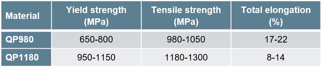
Table 3 contains typical mechanical property ranges for industrially produced QP980 and QP1180.W-35 A typical strain–stress curve of QP980 is shown in Figure 9.
Table 3: Typical mechanical property ranges for industrially produced QP980 and QP1180.W-35
Figure 9: Stress-strain curve of industrially produced QP980.W-35
Of course, there are additional characteristics beyond strength and elongation that impact successful use in manufactured products. Typical forming-limit curves for cold rolled QP980, DP780, and DP 980 steels are shown in Figure 10, highlighting that the formability of QP980 is comparable to that of DP780.
Figure 10: Forming-limit curves for 1 mm thick Q&P 980, DP 780, and DP 980.W-35
Figure 11 contains the results of high strain rate tensile testing, confirming that QP980 has positive strain rate sensitivity and therefore has the potential for improved crash energy absorption.
Figure 11: True stress-strain curves for QP980 generated at different strain rates.W-35
Sheared-edge ductility is also a concern in AHSS grades. Hole expansion of QP1180, QP980, and DP980 is compared in Figure 12, with similar results seen in QP980 and DP980. QP1180 had the highest hole expansion, possibly because of its microstructure containing components of relatively uniform hardness.
Figure 12: Hole expansion of QP1180, QP980, and DP980, generated from either punched or machined holes.W-35
The bending under tension test was used to determine the critical R/t value below which the risk for shear fracture increases. These experiments showed that critical R/t values of QP980 were close to those of other steels having 600 MPa tensile strength.W-35
Similar springback was observed in QP980 and DP980 when a 5 mm radius was used in the bending-under-tension test, with QP980 exhibiting less springback when a 12.7 radius die was used instead.W-35
General Motors provided stress-strain curves for production QP700/1180 tested at different strain rates (Figure 13), showing increases in strength and ductility as strain rates increase.H-60
Figure 13: Engineering stress-strain curves for QP700Y/1180T at different strain rates.H-60
The stress-strain curves of some advanced steels are compared in Figure 14. The ductility benefit of Quenched and Partitioned steels is seen in the greater elongation.
Figure 14: Stress strain curves of four advanced steels.
A recent conference highlighted several applications (Figure 15) where thinner gauge QP980 replaced DP590 in General Motors vehicles.W-37
Figure 15: Replacing DP590 with QP980 allows for downgauging.W-37
The same presentationW-37 showed the example of QP980 replacing press hardening steels in B-pillar reinforcements and door anti-intrusion beams in a First Auto Works vehicle, Figure 16.
Figure 16: QP980 may replace press hardening steels in some safety applications.W-37
Development work continues to extend the upper limits of strength. A grade referred to as S1500 has a martensitic matrix with retained austenite dispersed throughout. It is similar to QP980, but with a higher martensite content and a lower retained austenite content than QP980. S1500 has yield and tensile strength comparable to MS1500, but with substantially higher elongation to fracture (a measure of global ductility) and fracture strain within a very small region (a measure of local ductility).J-27
Table 4 shows the properties of these three grades, and a comparison of stress-strain curves can be found in Figure 17.
Table 4: Properties of Three Advanced High Strength Steels. Table based on Citation J-27.
Steel
Type
Thickness
(mm)
YS
(MPa)
TS
(MPa)
Fracture
Elongation (%)
n
r0
r45
r90
Fracture strain:
0.5 mm x 0.5 mm
S1500
1.5
1363
1503
12.90
0.04
0.79
0.83
0.80
0.520
MS1500
1.2
1311
1502
5.76
0.04
—
—
—
0.357
QP980
1.4
764
1085
19.70
0.16
0.85
0.91
1.03
0.441
Figure 17. Stress-Strain curves of MS1500, QP980, and S1500.J-27
The phase transformations occurring in the two grades containing retained austenite, combined with the impact on instantaneous n-value, help explain the difference in forming behavior with the grade that is 100% martensite, Figure 18.
Figure 18: Hardening curves and instantaneous n-values of S1500, MS1500, and QP980.J-27
Without any phase transformation in MS1500 (green curves in Figure 18), the instantaneous n-value peaks and drops down. Limited strengthening in this grade leads to relatively low elongation at break.
The relatively high n-value associated with QP980 (red curves in Figure 18) indicates a superior ability to distribute strains over a wider region than the other two grades, and is associated with substantial strengthening with strain (work hardening). The greater amount of retained austenite leads to the TRIP effect occurring early in the application of strain, leading to a rise in n-value in these early stages. QP980 continues to maintain a high n-value in the later stage of uniform deformation, leading to high elongation at break.
The S1500 (black curves in Figure 18) has a microstructure of nearly 90% martensite, so it is not surprising that during the initial application of strain, the behavior is similar to that seen in MS1500: The martensite deforms first. After an early peak in instantaneous n-value, it decreases rapidly. However, as application of strain continues, n-value begins to rise in the S1500 grade. This occurs because the retained austenite in the microstructure undergoes the TRIP effect and produces fresh strain-induced martensite.
MS1500 does not increase in the later stage of uniform strain. These differences may be correlated with the volume fraction of the retained austenite.
Enhancing the TRIP Effect in QP Steels
The strength-ductility balance of quenched and partitioned steels results from the TRIP effect. The magnitude of the TRIP effect is controlled by the amount of retained austenite in the microstructure. A thermal cycle known as Q&Q-P (pre-quenching followed by quenching & partitioning) can increase the volume fraction of retained austenite, and therefore improves the mechanical properties of these alloys.Z-17
The pre-quench process consists of austenitizing followed by quenching to room temperature. This results in a fine martensitic microstructure. This starting point leads to an increased density of austenite grain nucleation sites during subsequent annealing, producing fine austenitic grains. The second quench of the Q&Q-P process, or the initial quench of the Q-P process, is not taken to room temperature, but instead to a temperature between the martensite-start (Ms) and martensite-finish (Mf) temperatures. In the partitioning step, these quenched sheets are held either at or above this initial quenching temperature in order to enrich the untransformed austenite by carbon diffusion from supersaturated martensite.
A reduction in the austenite grain size from the pre-quench step increases the austenite stability by lowering the starting temperature for martensitic transformation, thereby suppressing the martensite transformation, meaning that the TRIP effect continues to enhance ductility even at greater forming strains. Smaller austenite grain size results in increased strength, and increases the mechanical free energy required to transform into martensite.
A schematic of the Q&Q-P and Q-P process is shown in Figure 19.
Figure 19: Schematic of the Q&Q-P (with prequench) and Q-P (Quenching & Partitioning) heat treatment cycles.Z-17
The time of partitioning influences properties due to the change in the volume fraction of retained austenite, as indicated in Table 5. Even with the impact of the partitioning time, the pre-quench process results in a substantial increase in retained austenite.
Table 5: Volume fraction (%) of retained austenite as a function of partitioning time in the Q-P and Q&Q-P process. Z-17
5 s
10 s
20 s
50 s
100 s
200 s
Q-P
13.9
11.6
11.3
10.5
12.1
11.2
Q&Q-P
19.3
19.9
22.5
20.4
20.4
21.6
The microstructure of Q-P samples consists of martensite and retained austenite, where the martensite deforms plastically in the early strain stage, leading to local stress concentration occurring at small strains. The retained austenite transforms in order to relieve the local stress concentration and is exhausted at these small strains.
In contrast, the Q&Q-P samples contain ferrite, which is the first to deform preferentially in the early strain stages. This behavior, plus the higher volume fraction of retained austenite, allows the Q&Q-P samples to continue deforming by the TRIP effect at higher strains. Depending on the partitioning time, 1000 MPa tensile strength with elongation approaching 30% is achievable.Z-17
Medium Manganese Steels, Medium-Mn, or Med-Mn
Manganese has a lower density than iron, so using alloys with higher amounts of manganese truly creates lightweight products. 1st Generation steels typically contain no more than around 2% Mn. 2nd Generation TWIP steels have about 20% Mn. Lean medium-manganese (MedMn) steels typically use between 3% and 12% manganese along with silicon, aluminum, and microalloying additions.R-16, D-27, S-80, K-35 Aluminum in these steels further lowers the density.
No standard chemistry or processing route exists, but several studies use a thermal cycle similar to that seen with Q&P steels. This approach leads to a complex multiphase fine-grained microstructure. Compared with QP steels at the same strength levels, the higher manganese levels of Med-Mn steels promote greater amounts of retained austenite, and therefore greater ductility through the TRIP Effect. One study showed a combination of 1400 MPa tensile strength and a total elongation of 18%.S-103
One difference from the thermal cycle to produce QP steels used by some researchers to process Med-Mn steels is that after intercritical (two-phase) annealing, the quench is to room temperature rather than simply below Ms, the start of martensitic transformation.S-80 This is facilitated by the high levels of manganese, which adjusts the Mf below room temperature. Quenching a steel containing 0.25% C, 8.23% Mn, 1.87% Si, 0.05% Ni, and 0.24% Mo to room temperature and subsequently partitioning at 300 °C led to tensile strengths greater than 1800 MPa combined with total elongations of approximately 15%.S-80
In addition to lowering the Mf (martensite finish) level below room temperature, the manganese levels are sufficiently high enough that the coils after hot rolling may be either partially or fully martensitic. This phenomenon means that it may be possible to produce hot rolled Med-Mn steels.
Another production method called Austenite-Reverted Transformation (ART) annealing results in a large percentage of retained austenite in medium manganese steels. The fully or partially martensitic hot or cold rolled coil is heated to the single phase austenite region or the intercritical two phase austenite+ferrite region where the martensite reverts to austenite – hence the name of the process. The austenite nucleates on the former sites of fine martensitic features. This approach results in a final product with extremely fine features. During annealing, diffusion of both carbon and manganese occurs, which determines both the phase fraction and stability of the retained austenite. Processing of Fe–0.3C–11.5Mn–5.8Al resulted in a microstructure with 60% retained austenite.B-59
Multi-step thermal treatments are one approach to control the relative proportions of martensite, ferrite, and austenite. One example, termed “double-soaking” (DS), aims for substantial Mn-enrichment of austenite in a first soaking step followed by a second soaking step at a higher temperature which leads to a greater fraction of martensite in the final product. The brief second soak is long enough to allow the carbon to partition, but not long enough for manganese partitioning to occur, producing regions of higher and lower Mn within the austenite. The higher-Mn regions allow for greater amounts of austenite in the final product, while the lower-Mn regions transform to martensite, leading to TRIP-effect ductility and high strength.S-80, G-47 In an industrial environment, the initial soak may be done in a batch anneal furnace, with the brief second soak targeted for the time and temperature available in continuous annealing or galvanizing lines.
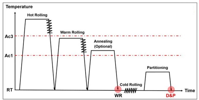
Still another production method proposed is known as Deforming and Partitioning (D&P). This route uses a warm rolling followed by cold rolling to generate an extremely high dislocation density. A subsequent partitioning treatment relieves the residual stresses from rolling and stabilizes the retained austenite via carbon enrichment. Figure 19 shows a representative Deforming and Partitioning thermal cycle. A D&P MedMn steel with a composition of 0.47C–10Mn–2Al–0.7V reached a yield strength of 2.2 GPa (2,200 MPa) and a uniform elongation of 16%.H-65
Figure 19: Representative Deforming and Partitioning (D&P) thermal cycle.H-65
Medium-manganese steels with Mn contents between 3 wt.% and 10 wt.% have a microstructure consisting of an ultra-fine grained ferritic matrix (grain size < 1 μm) with up to 40 vol.% retained austenite.K-47 A chemistry of Fe-7.9Mn-0.14Si-0.05Al-0.07C resulted in 39% retained austenite with the processing route evaluated.Z-10
Properties are dependent on all aspects of the chosen chemistry and thermal cycle. With an appropriate approach, the steel may exhibit both a transformation-induced plasticity (TRIP) effect and a twinning-induced plasticity (TWIP) effect.
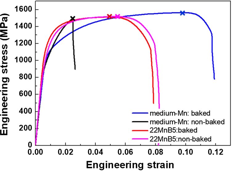
Studies indicate that Medium Manganese steels are also suitable for use in press hardening applications. A studyL-63 indicates that an alloy with 0.14 %C – 7.0 %Mn rivals conventional 22MnB5 PHS1500 in strength, but has more ductility. After hot forming and processing through a typical paint bake cycle, 22MnB5 exhibited a tensile strength of 1510 MPa, a uniform elongation of 4.6%, and a total elongation of 7.3%. The MedMn steel showed values of 1565 MPa, 9.6% and 11.7% respectively, Figure 20. These enhanced properties are suspected to be associated with the high volume fraction (15%) of retained austenite found in the Medium Manganese steels.
Figure 20: Engineering stress–strain curves of the medium-Mn martensitic steel and 22MnB5.L-63
Unlike TBF and QP steels, Medium-Manganese steels may exhibit discontinuous yielding, also known as yield point elongation or Lüders bands. Depending on chemistry and processing, these may extend beyond 5% engineering strain.
Medium manganese steels are not yet widely commercialized. They were the focus of an entire issue of a technical journal.M-58 The lead Editorial presents an overview of prior studies and highlights areas of interest.R-16
The WarP-AHSS project seeks to develop end-to-end processing of warm press-formed parts from zinc-coated Medium Manganese Steels. This approach is expected to reduce the reheating and warm press-forming temperatures, making the process greener and energy-efficient, while allowing the use of zinc-coated sheets without liquid metal embrittlement-induced micro-cracking during warm-forming.
Partners in the WarP-AHSS research project include a steelmaker, an automaker, a university, and two research institutions. The project runs from October 2023 through March 2027.
The European Research Executive Agency has funded another multi-year study, Sup3rForm, that seeks to optimize the production and use of both 3rd Generation Q&P and medium-Mn steels. The Sup3rForm consortium, coordinated by Eurecat Technology Centre, is made up of eight partners, including steelmakers, an automaker, tier suppliers, and universities. Sup3rForm runs from July 2023 through December 2026.
Approaches for forming higher strength steels evolved with the commercialization of increased strength levels of High Strength Low Alloy (HSLA) steels. Demands for greater crash performance while simultaneously reducing mass and cost have spawned the development of new groups of steels that improve on the properties of these HSLA steels. Forming of Advanced High-Strength Steel (AHSS) is not a radical change from forming conventional HSLA steels, providing some of the key differences are understood and accounted for in die design, die process, and equipment selection.
AHSS grades solve two distinct automotive needs by two different groups of steels. The first group as a class has higher strength levels with improved formability and crash-energy absorption compared to HSLA grades. DP, TRIP, FB, and TWIP steels, which have increased values of the work hardening exponent (n-value), fulfill this requirement. The second group, including CP and MS steels, extends the availability of steel in strength ranges above what is available with HSLA grades. Originally targeted for chassis, suspension, and body-in-white components, AHSS grades are now being applied to doors and other body panels. New variations in microstructure help meet specific process requirements, including increased edge stretch, bendability, strengthening after forming, or tighter property tolerances.
The progressive increases in yield and tensile strength with these new AHSS grades magnifies existing forming issues with conventional HSLA grades and creates new challenges. Concerns include higher loads on processing equipment including presses, levelers, straighteners, blanking lines, coil slitting lines and roll forming equipment. Additionally, there are material and surface treatment considerations required for tooling in the stamping plants: draw dies, trim steels, and flange steels. Compared to conventional HSLA steels, greater energy requirements result from higher AHSS yield strengths, tensile strengths and significantly higher work hardening rates. This places new requirements on press capacity, leveler, straightener and slitting capabilities, tool construction/protection, lubricant capabilities, part and process design, and maintenance. Springback management becomes more critical as yield strengths continue to increase. Conventional and press hardened (hot formed) AHSS parts have very high strength after forming, so re- forming operations should be avoided. Trimming, cutting, and piercing equipment must be constructed and maintained to overcome the extreme high strength of the final stamping. Laser cutting of press hardened parts produces a finished part that avoids pushing the limits of trim and pierce tools and dies utilized for conventional HSLA steel.
There are an ever-increasing number of AHSS multiphase microstructure grades available, each designed to resist various forming failure modes while achieving final part performance requirements. Sharing of information regarding the planned part geometry, die and stamping processing, and final part application between steel suppliers, product and die process engineering, and end users helps ensure selection of the right steel grade for the application. This becomes especially relevant since multiphase microstructures experience additional forming failure modes compared with conventional high strength products.
Tool Design Considerations
The characteristics associated with different AHSS grades influence die design and die processing decisions. Not only are these steels typically higher in strength, but they also undergo substantial work hardening during forming. These lead to increased local loads, and changes in friction, die wear, and press requirements. The multiphase microstructures increase cut edge and bending fracture sensitivity. As such, extending the life and performance of tooling in press shops requires a rethinking of tool and part design.
Part Design
Successful application of any material requires close coordination of part design and the manufacturing process. Consult product and manufacturing process engineers when designing AHSS parts to understand both the limitations and advantages of the grade and the proper forming process to be employed. Start in the concept and feasibility stage to ensure sufficient time for corrective actions and optimization.
Soft tool materials like kirksite may be used for manufacturing prototype parts and the inserts used to eliminate local wrinkles or buckles. However, wear resistant coatings are typically not applied to these tool surfaces, so the metal flow seen in these prototype parts may not match the metal flow seen under production conditions. The results from soft tool tryouts should not be used to assess manufacturability and springback of AHSS parts.
Design structural frames (such as rails, sills, cross members, and roof bows) as open-ended channels to permit forming operations rather than draw die processes. AHSS stampings requiring closed-end draw operations are limited by a reduced depth of draw, Figure 1. Less complex, open-ended stamped channels are less limited in depth. A rule of thumb is that DP 350Y600T can be formed to only half the draw depth of a mild steel.
Figure 1: Schematic of an open end part design (left) and a closed end part design (right). The open-ended design allows for greater depths when utilizing AHSS versus the closed ended design historically used with mild steel.A-5
Where possible, avoid closed-end developments to make more complex geometries with AHSS grades. Wrapping ends of “hat” sections increases forming loads, increases the chances of circumferential compression wrinkling on the binder, specifically in the corners, and increases wrinkling on the draw wall if the blank edge runs through the draw bead. Draw die developments that include a closed (or wrapped) end development usually also require a larger blank size. During draw die development, it is best to identify parts that have a “hat” section geometry in certain locations and develop the draw die accordingly to maximize the positive formability attributes of AHSS while minimizing the limitations of AHSS.
For example, the left image in Figure 2 shows a draw die development on a DP600 cowl side with a closed (wrapped) end, with the right image showing a similar part developed with an open end. Although both final part geometries are similar, the closed-end development led to significant global formability failures due to the excessive stretch. In contrast, the open-ended development had virtually no global formability related failures. Other design and die development differences in the part on the right include the use of stake beads to control springback and embossments to eliminate wavy metal. In addition, an open-ended development has the potential to reduce the blank size for material utilization savings.
Figure 2: Draw die development for a cowl side formed from DP600. Left image: closed-end development with global formability failures, waviness, and springback. Right image: open-ended development with no splits, waves, or dimensional concerns.U-6
The automotive industry has adopted a strategy for “lighter dies and fewer dies”, to reduce cost. One key element is “part consolidation”, such as one-piece body side outers and inners. High strength steels challenge the part consolidation mantra. When encountering extreme formability challenges, parts previously made with one set of dies when stamped from lower strength steels may benefit from transitioning to a laser welded blank with a lower strength grade in the challenging region and higher strength steels in the remainder of the part. Alternatively, splitting the consolidated part into two or more separate parts subsequently welded together may improve stamping success at the expense of another operation. In the past, one-piece rocker panels were stamped from conventional mild or HSLA steel. However, this component requires higher strength and reduced thickness to meet weight and crash requirements, so now DP980 is often considered as the grade of choice for this application. Figure 3 shows a rocker panel where insufficient formability of DP980 prevented a one-piece stamping. The OEM solved this by dividing the part into two stampings, putting a more formable grade where needed on the wrapped (or closed) end.
Figure 3: When a one-piece rocker panel could not be successfully formed from DP980, the OEM stamped a DP980 rocker panel section with an open-ended design and spot welded it to a mild steel end cap.U-6
Trim and Pierce Tool Design
Trim and pierce tools need to withstand higher loads since AHSS grades have higher tensile strengths than conventional high-strength steels.
Edge cracking is minimized with proper support of the trim stock during trimming.
Modify timing of the trim/pierce operation to minimize snap-through reverse loading.
Scrap shedding may be an issue, since AHSS springback can cause scrap to stick in the tool.
Flange Design
Design more formable flanges to reduce need for extra re-strike operations.
Areas to be flanged should have a “break-line” or initial bend radius drawn in the first die to reduce springback.
Adapt die radii for material strength and blank thickness.
Draw Bead Design
Metal flow across draw beads generates strain and minimizes the elastic recovery which causes springback.
Metal flow across draw beads generates large amounts of work hardening, leading to increased press loads.
Optimizing blank size and shape reduces the reliance on draw beads, which can excessively work harden the material before entering the die opening.
Guidelines to Avoid Edge Cracking During Stretch Flanging
Flange length transition should be gradual – abrupt changes in flange length cause local stress raisers leading to edge cracks.
Avoid the use of sharp notch features in curved flanges.
Avoid putting bypass notches in stretch or compression edges of blanks or progressive die carrier strips. These bypass notches can act as stress risers and lead to edge fractures in the draw or flange operation. In addition, bypass notches in blanks and progressive dies are difficult to maintain, which can increase the potential for edge fracture.
Metal gainers in the draw die or in the die prior to the stretch flange operation compensates for change in length of line that occurs during flanging, helping to avoid edge cracking. In the example shown in Figure 4, edge fractures moved from the draw panel to flanged panel after grinding on the draw die to eliminate edge fractures in the draw operation. The draw panel underneath the flanged part in Figure 4 did not have edge fractures. The reduction in the length of line in the draw operation moved the problem to the flanged part where the stamping transitioned from bending and straightening in the flange operation to a stretch flange operation. A better practice is to add metal gainers to the draw panel to provide the feedstock which expands during stretch flanging.
Figure 4: Flanged panel fractures, with the draw panel underneath. Adding metal gainers to the draw panel would help minimize these fractures.U-6
The higher strength of AHSS makes it more difficult to pull out loose metal or achieve a minimum stretch in flat sections of stampings. Addendum, metal gainers (Figures 5 and 6), and other tool features balance lengths of line and locally increase stretch.
Figure 5: Metal gainers help avoid insufficient stretched areas and eliminate buckles.T-3
Figure 6: Metal gainers and depressions balance stresses and minimizes wrinkled metal.A-41