R-9
Citation:
R-9. D. Kim, “Roll Stamping Device”, Patent KR101786260B1 Issued to Don-Gun Kim and assigned to POSCO Co. Ltd.

R-9. D. Kim, “Roll Stamping Device”, Patent KR101786260B1 Issued to Don-Gun Kim and assigned to POSCO Co. Ltd.
A-48. “Apparatus for roll stamping,” Patent KR101417278B1 Issued to Don-Gun Kim and assigned to POSCO Co. Ltd.; Available from patents.google.com/patent/KR101417278B1/en
Lubrication is a key input into the sheet metal forming process. The chosen lube, application method, distribution, and cleaning method influences forming and subsequent operations.
Lubricants serve many roles in sheet forming. The functions below become more challenging as the strength of the sheet metal increases, resulting in higher forces, contact pressures, and temperatures. Therefore, special attention to lubrication and the effect of heat are required when considering lubricants for forming Advanced High-Strength Steels (AHSS).
Higher strength steels (both conventional and AHSS) have less capacity for stretch (less work hardening or n-value than mild steels) over the punch to generate the required length of line. As the steel strength increases, more metal must flow from the binder into the die to compensate for the loss of length of line for a required stamping depth. Tensile stresses are applied to the metal under the binder in the radial direction (perpendicular to the die radius) to pull the metal towards the die radius. Compressive stresses can form in the circumferential direction (parallel to the die radius) as the blank reduces its circumferential length. While this compression usually happens in box corners, it also can happen in sidewall features that shorten the length of line while moving into the stamping. Metal flowing uncontrolled into a sidewall also can generate compressive circumferential stresses. These compressive stresses tend to buckle the binder metal rather than uniformly increase the local thickness. This buckling is following the law of least energy-forming mode in sheet metal forming. Less energy is required to form a local hinge (a buckle) using only few elements of the sheet metal compared to uniformly in-plane compressing the metal to generate an increase in thickness for a large number of elements.
Weight reduction programs use higher strength steels to reduce the sheet metal thickness. The thinner sheet metal is more prone to buckling than thicker steels. Therefore, part designs utilizing AHSS with thinner sheets can require significantly higher blankholder forces to flatten buckles that form. Since restraining force is a function of the coefficient of friction (C.O.F.) multiplied by the blankholder force, the restraining force increases and metal flow decreases. Deforming AHSS requires more energy. This combination results in higher contact pressure between the metal and the die, and higher interface temperatures. Counter measures include an improvement in lubrication with a lower coefficient of friction, and the ability to maintain viscosity at elevated temperatures; other process changes may be required to compensate for the pressures and temperature effects.
Higher forming energy causes both the part and the die to increase in temperature. For example, a study by IrmcoJ-16 measured the temperatures on stampings produced from 4mm thick 350 MPa and 560 MPa steels, with a production rate of either 10 or 13 strokes per minute. Increasing strength levels result in higher part temperatures, which is made more significant at higher stroke rates, Figure 1. The die temperatures are also significantly higher, and conventional water-based and oil-based lubricants may suffer viscosity reduction, with a corresponding increase in the coefficient of friction.
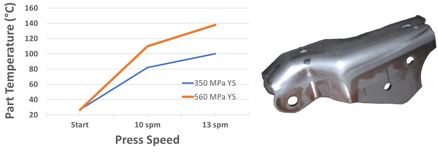
Figure 1: Part and tooling temperatures increase when stamping higher strength steels.J-16
Several lubrication studies have been performed over the years, including Citation P-11 and many others from The Center for Precision Forming (CPF) at Ohio State University.K-19, H-24, F-13 Figure 2 shows the temperature profile after a single stroke of deep drawing a 1.2-mm-thick DP980 part (470 by 300 mm) in a 300-ton AIDA servo press with CNC hydraulic cushion.F-28
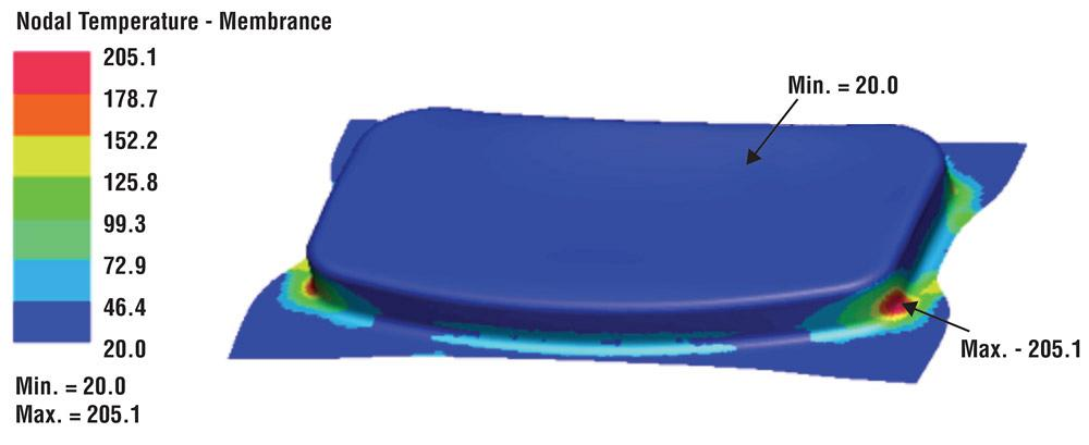
Figure 2: Temperature profile after deep drawing a 1.2mm DP980 part in a servo press with a hydraulic cushion.F-28
The highest temperatures exceeding 200 °C are found on the die opening radius – reinforcing that part and die temperatures increase with increasing material strength. Without high-temperature tolerant additives, the lubricant effectiveness deteriorates, resulting in galling and subsequent scoring of the sheet metal. All these events increase blankholder-restraining force and inhibit metal flowing into the die. As production speed increases (the number of strokes per minute), the amount of heat generated increases, with a corresponding increase in sheet metal and die temperature.
One approach to addressing the heat problem when forming higher strength steels is application of lubricants that are less prone to viscosity changes with temperature, and lubricant film breakdown. Water-based lubricants disperse more heat than oil-based lubricants. Successful forming of some parts may require tunnels drilled inside the tooling for circulating cooling liquids. These tunnels target hot spots (thermal gradients) that tend to localize deformation leading to failures.
The metalforming lubrication system is complex, affected by numerous factors.H-25 The information provided here is a general overview, but it is recommended that personnel selecting lubricants consult their lubricant supplier(s) regarding the specific requirements of each application.
TribologyA-50 is the science of friction, lubrication, wear, and erosion. Triboelements are the interacting surfaces in a tribosystem; the tool and workpiece in sheet metal forming. A tribosystem is any system containing triboelements, including all mechanical, chemical, and environmental factors relevant to the tribological behavior. These include the materials and surface properties, contact geometry, loading, motion, and environment. All these factors may influence the coefficient of friction. Coefficient of friction (µ) is the ratio of the force required to move one surface over another contacting surface (F) to the applied normal force (P).S-62
µ = F/P
In forming of High-Strength Steels (HSS), the combination of high interface pressures, sliding contact, and expanding surfaces resulting in lubricant starvation makes boundary lubrication particularly important in preventing lubricant film failure and adhesion or galling. Boundary lubrication is when the coefficient of friction is a function of the properties of the surfaces in contact, and the lubricant, other than viscosity.O-5 Polar boundary lubricants adhere to the surfaces, forming thin films, which prevent or delay adhesion and galling. Extreme pressure (EP) is a type of boundary lubrication where the EP additive, typically chlorine, sulfur, or phosphorus bearing, reacts with the metal surface, forming metallic salts, along with other reaction products, which provides a lubricating barrier (tribofilm) between the surfaces. These are generally thought to be effective up to the melting point of the metallic salt. For phosphorus, this is about 205 °C, chlorine 700 °C, and sulfur 960 °C. A typical polar organic boundary lubricant like fatty acid soaps are generally not effective much above 100 °C.M-23 EP additives are often combined in lubricant formulas along with other boundary lubricants to optimize performance across a range of conditions and take advantage of synergies. Chloride salts on the metal surface makes rust protection more challenging with chlorinated EP lubricants. This factor and continuous regulatory pressure have resulted in the decreasing use of chlorine-bearing additives.
Initial activation of EP lubricants was previously believed to be almost completely thermally driven, with graphs like Figure 3L-32 indicating activation and breakdown temperatures. It has since been shown that initial activation of boundary additives depends on both the applied shear stress and temperature, and is the subject of ongoing research.S-69, A-53,Z-8 For operations above these temperatures, non-reactive inorganic solids may be used, including graphite, molybdenum disulfide, calcium carbonate, and nanoparticles.
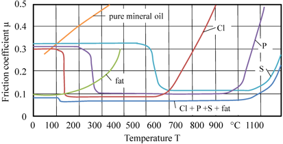
Figure 3: Activation and breakdown temperature of various additives used in metalforming lubricants.L-32
Liquid metalforming lubricants may be classified by the amount of mineral oil contained within them.B-35, A-54
Lubricants used to form HSS may be further classified according to their application and how they are used.B-34
Press applied metalforming lubricants: These are applied at the press and may be straight oils, heavy duty emulsifiable oils or pre-formed emulsions, or water-based synthetic formulations depending on the severity of the operation and materials being formed. This type of lubricant is most likely to contain EP lubricant additives.
Figure 4 compares important capabilities of some of the types of metalforming lubricants used for forming HSS (after Citation B-35). Prelubes are not shown specifically, but they are similar to mill oil in most respects, but with much improved lubricity. Prelubes are meant to replace press applied lubricants. This figure ranks typical performance levels, as there can be a range of capabilities for each product type. Consult your lubricant supplier(s) for specific information on their products.
![Figure 4: Comparison of important characteristics associated with different lubricant types, where higher values are better [After Citation B-34].](https://ahssinsights.org/wp-content/uploads/2021/02/2.11.5-Fig4-SpiderGraph.svg)
Figure 4: Comparison of important characteristics associated with different lubricant types, where higher values are better (After Citation B-35).
Mill applied lubricants, including dry barrier lubricants, mill oils, and prelubes, are typically applied electrostatically, resulting in thin (approximately 1.0-1.5 g/m2) uniform coatings prior to re-coiling. However, liquid lubricants may migrate within stored coils resulting in areas of thicker and thinner lubricant films. This can affect friction, resulting in a less robust stamping process. Research has shown that electrogalvanized sheet is more sensitive to lubricant chemistry, while galvanneal is sensitive to the lubricant film thickness.D-24 Several commercial oil film thickness measurement instruments are available from various sources.
Several methods and equipment are capable of coating sheets with press applied lubricants.B-36 Manual application with rollers, brushes, and swabs requires little expense, but is generally slow and presents housekeeping challenges. Roller coaters and spray systems are more frequently used. Roller coaters are limited by blank size and steel must be flat. Spray systems can accommodate lubrication in multiple stations, useful for cooling, and is not part shape or size limited. High viscosity lubricants may be difficult to spray. Flood systems offer excellent cooling. Blankwash systems are recirculated flood applications. These must be monitored for changes with use as recommended by the suppler, including contamination, microbiology for water-based lubricants, and viscosity for oil based lubricants.
Iron is available on the surfaces of bare steel and galvanneal to react with conventional EP additives bearing sulfur, phosphorus, and chlorine to form effective tribofilms. However, pure zinc hot dipped and electrogalvanized surfaces show only moderate response to additives.S-70 Galvanneal and electrogalvanized microscopic surface features help retain lubricant for the metalforming operation.S-70 Several sources suggest that the coefficient of friction on hot dipped galvanized surfaces vary less than that seen on electrogalvanized surfaces.
Table I presents guidelines for lubricant selection when forming AHSS.B-37
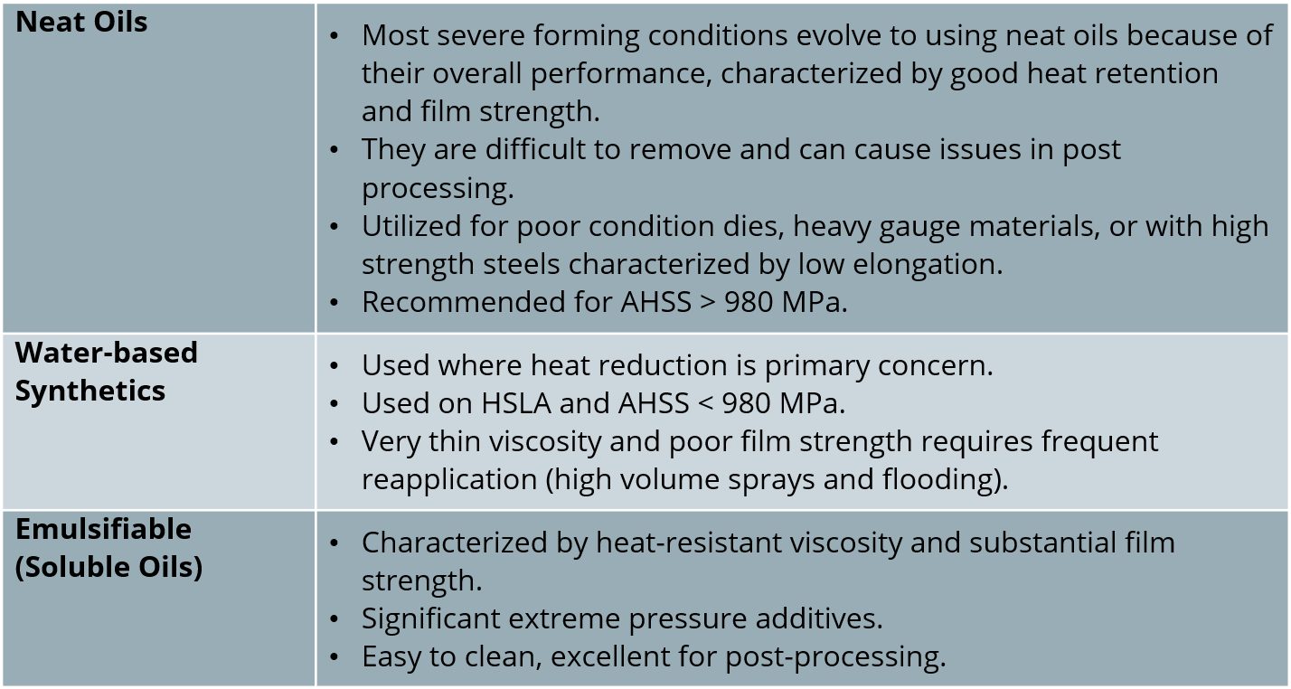
Table I: Lubricant Selection Guide for Forming of AHSS.B-37
Metalforming lubricant manufacturers and end-users conduct many different friction tests to screen lubricants prior to plant trials and to collect friction data for use in modelling. The questions of which test(s) are most applicable to specific operations, and what testing parameters are appropriate for testing, are important considerations. Tribosystem analysis (TSA) is a systematic method that may be applied to a metalforming operation, as well as laboratory tests being considered for use. These analyses are compared in order to determine which laboratory tribotest may be most applicable.S-71 Matching parameters, including test materials, surface features, contact type, and mode of failure are some of the most basic considerations.
Laboratory tribotests have been divided into two main categories: simulation and bench tests. Simulation tests take a metalforming process and scales it down for laboratory use. They are used to study the influence of variables on production, including lubrication. Examples include draw bead simulator (DBS) and cup draw tests (CDT). Bench tests create specific tribological conditions and are used to understand basic phenomena, but may also be applied to results in production, if both the laboratory and production lubrication and wear mechanisms are understood. Examples of bench tests include bending under tension (BUT) and twist compression tests (TCT).S-72
FEM programs have used a single coefficient of friction value in modelling. The coefficient of friction is not uniform across all areas of a part during forming. Programs have been developed that include sheet material and surface properties, lubricant parameters, and tool information to supply FEM programs, friction models for improved accuracy.
High die and part temperatures reached in HSS forming operations puts additional strains on lubricants. EP lubricants are often required at these elevated temperatures. This is particularly true in situations prone to buckling, which creates areas of very high contact pressures, potentially leading to galling. Straight oil viscosity decreases with increasing temperature. The amount of viscosity decrease between 40 °C and 100 °C is reflected in the oil viscosity index (VI).A-55 Reduced oil viscosity can affect lubrication properties.
Some lubricants may emit smoke and odors that must be controlled or eliminated in the workplace. Within base oil types, smoke and flash points increase with viscosity. For a given viscosity, naphthenic base oils have lower smoke and flash points than API Group I, II, III, and IV base oils. Synthetic esters and vegetable oils generally have higher smoke and flash points than corresponding viscosity petroleum oils. Higher temperatures also can increase the oxidation of lubricant residues on parts, forming acidic and polymeric residues, making the lubricants more difficult to remove prior to finishing and potentially reducing interim corrosion protection properties. Antioxidants are often used in lubricants to slow oxidation for this reason. Polymeric oxidation products on steel surfaces, due to high temperatures, may also interfere with welding, adhesive bonding, and coating.
Associations and OEMs have established test programs for testing sheet metal forming lubricants for corrosion protection, cleanability, phosphate application, and coating, as well as adhesive, sealer, and welding compatibility.A-56 Generally, aging of the lubricant films is done before running these tests to simulate time in storage. Higher forming temperatures for HSS can potentially influence performance of lubricants for all these parameters. Tier suppliers within the automotive supply chain are encouraged to use only those lubricants on the OEM approved supplier list.
Sustainability in automobile manufacturing is gaining importanceE-6, which impacts the selection of materials, including metalforming lubricants. Verband Der Automobilindustrie (VDA) published their recommendationsE-4 for guiding principles in the automotive industry for improving sustainability in the supply chain. This includes questionnaires for suppliers and subsuppliers.
 |
Thanks are given to Ted McClure, SLC Testing Services / Sea-Land Chemical Co., who contributed this article. |
F-12. A. Fallahiarezoodar, B. Aykas, D. Diaz-Infante, and T. Altan, “Practical methods for estimating formability of sheet materials,” Stamping Journal, July/August 2016.
As with resistance spot welding in automotive applications, projection welding also is used to join two overlapping sheets of relatively thin metal. The process involves pressing a projection or number of projections in one of the plates and welding the two plates together at the projection locations.
The method can also be used for welding metal sheet to the ends of bars, rods or pipes, or for welding bolts, nuts, and other attachments to sheets. Such attachments are being used widely in the automotive industry. Wire grids (i.e. the crossing points of the wires) are also particularly suitable for projection welding (it is also called cross wire welding).
A modern car body may contains some 300 welded and punched fasteners, such as bolts, nuts, and studs. The quality of the attachment of these fasteners to the stamped body components is critical for the final product’s safety and reliability. Crucial components such as the front and rear axles are mounted to such fasteners, the seat belts and steering column are anchored to them, and they provide grounding for electrical wires.L-25
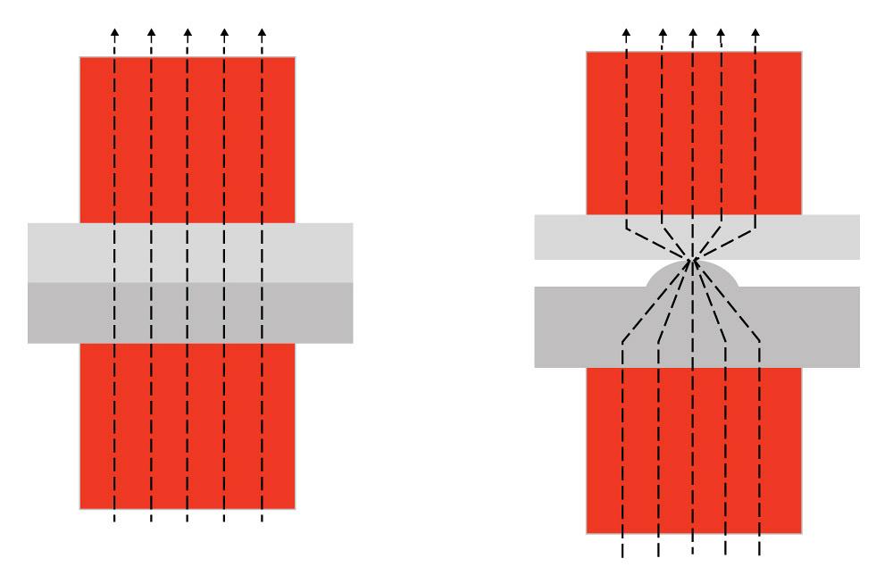
As noted, projection welding is similar to resistance spot welding. However, in the Resistance Spot Welding process, the size of the contact surface of the electrode cap tip determines the current flow, whereas in projection welding, the current flow is constricted to the embossed or machined projection as shown in Figure 1. Both AC and DC power sources are suitable for fastener welding. The heat balance for projection welding is affected by the following factorsA-11:
As compared to Resistance Spot and Seam Welding, Resistance Projection Welding is capable of welding much thicker parts, as well as parts with a significant thickness mismatch. As a result, it is often considered as a potential replacement for arc welding processes such as GMAW. One of the reasons for this is the drastic reduction in welding time that can be achieved. For example, a typical automotive part that might require several minutes or more of welding with the GMAW process may have the potential to be welded in less than a few seconds with the Resistance Projection Welding process. This is because the entire weld or multiple welds can be made at the same time in a single fixture. Another advantage of the process, relative to spot welding, is that there is less wear and tear on the electrodes.
Different types of projections made by different methods are shown in Figure 2. It is important to note that the types of projections that are extensions of the part are known as solid projections (2-B and 2-D) and can only be produced by a machining or forging process, whereas the other projections are more easily produced by stamping with a punch and die. Projections produced with a punch and die usually involve the formation of a molten nugget during welding but not always. The solid projection designs mostly result in solid‐state welds that occur via a forging action as the projection is heated and pressure applied. A common Projection Welding application that uses solid projections involves the attachment of a wide variety of nuts, bolts, and fasteners. Many fasteners used on automobiles are attached this way.
Figure 1: Welding current flow concentration due to projection geometry.
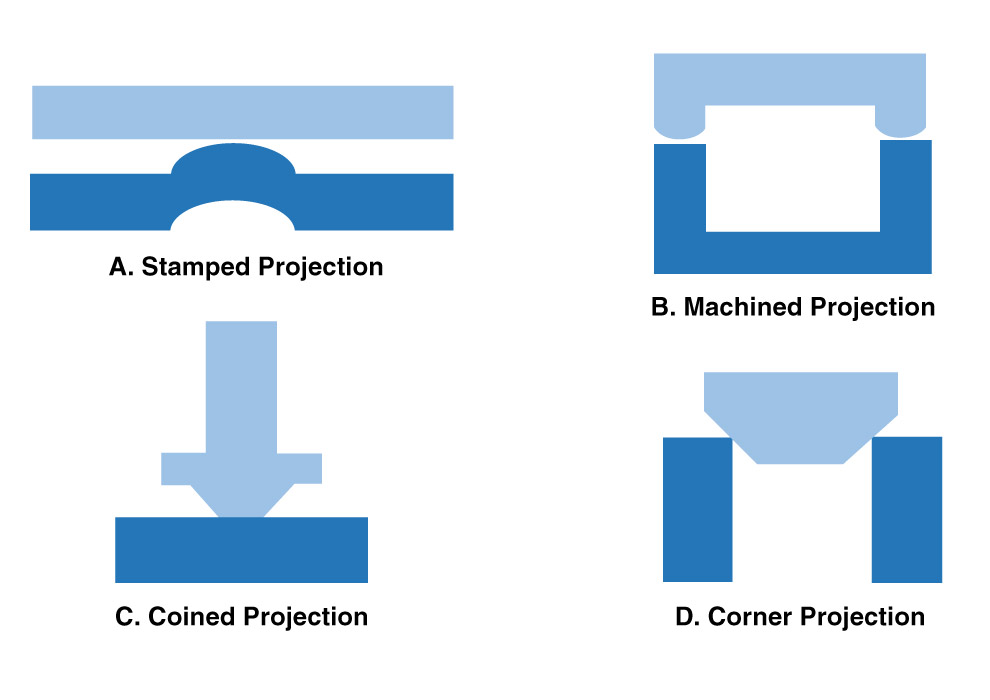
Figure 2: Typical projection types and designs.