The transportation industry’s contribution to greenhouse gas (GHG) emissions and global warming is well documented and understood. Vehicle OEMs, fleet operators, and transport users all have responsibilities to reduce environmental impacts on the planet and contribute to meeting global emissions regulations.
Mobility as a Service (MaaS) solutions like WorldAutoSteel’s flaghip Steel E-Motive (SEM) program have the potential to contribute to a reduction in GHG emissions, helping to achieve these global targets and specific policy objectives. The Steel E-Motive engineering report, released in 2023, addresses the impact of emissions reduction using Life Cycle Assessment, with key results summarized in this article.
Introduction to Life Cycle Assessment
Life Cycle Assessment (LCA) is a methodology that evaluates the environmental impact of a product across its entire lifecycle. By understanding the impact across the entire vehicle life cycle, vehicle manufacturers evaluate trade-offs and assess the net impact of the product they’re using.
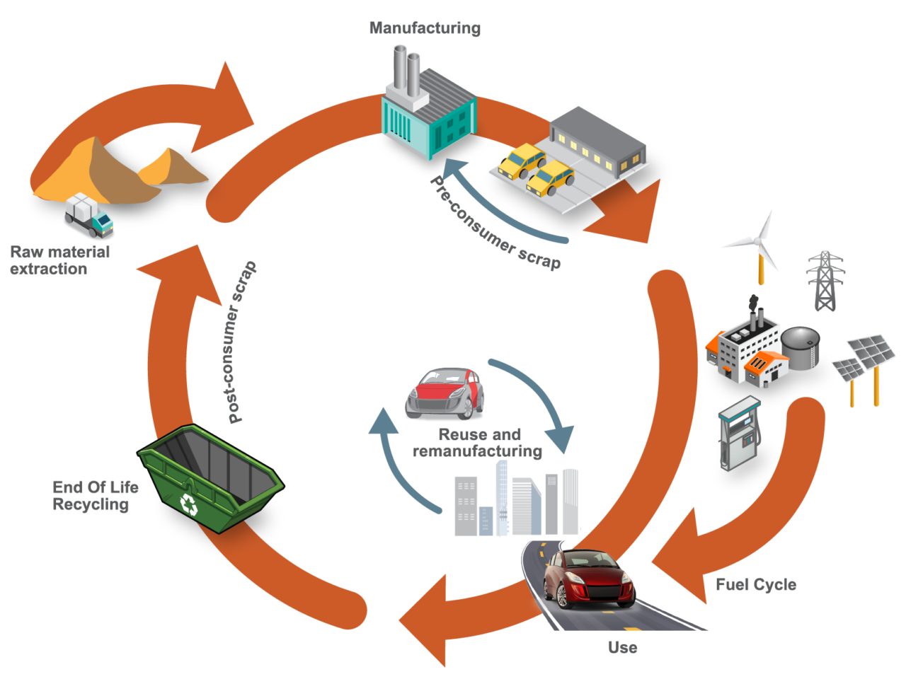
Cradle-to-grave assessments utilize a boundary that includes impacts from the production phase (including raw material extraction and vehicle production), the use phase (including fuel or electricity as well as consumables like tires and fluids) and the end-of-life phase, which could include disposal and/or recyling of the product, as shown in Figure 1. We applied LCA throughout the development of the SEM concept.

Figure 1. SEQ Figure \* ARABIC 1 Life Cycle Assessment, considering the entire life of the vehicle, from raw material extraction to end of life
LCA can cover a range of environmental impacts; however, for the SEM program, we focused on GHG emissions through the GWP-100 indicator and total energy consumption using Cumulative/Primary Energy Demand and Fossil Energy Consumption indicators.
Reference Taxi (Baseline) Vehicle
A key consideration in LCA calculations is establishing an appropriate reference vehicle. For this program, the following criteria was used:
- Present day (~2020) battery electric vehicle (BEV) operating in taxi mode with a driver and one occupant with vehicle/battery lifetime assumptions of 300,000km, and use of 100 percent conventional steel/aluminum.
- Vehicle end-of-life methodology using the Avoided Burden Approach, where recycled metals are assumed to displace equivalent quantities of their virgin counterparts and assigned corresponding emission and energy demand credits.
- Assumption of 50 percent pyrometallurgical recycling for the battery packs.
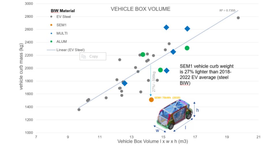
- Estimated reference taxi vehicle curb weight using the statistical reference data study (Figure 2), resulting in an estimated curb weight of 1,949kg.
- Material utilization based on data from a similar vehicle specification, as shown in Figure 3.
- Vehicle occupancy rate assumptions of 1.4, based on a combination of both “empty” and passenger-carrying journeys.

Figure 2. Vehicle curb weight versus box volume comparison. Reference vehicle data; source www.a2mac1.com
Steel E-Motive “Default” Vehicle
SEM vehicle life cycle calculations assume a hypothetical 2030 manufacture and start-of-operation date of 2030 to 2035. We updated the electricity grid supply mix to include the average of the International Energy Agency (IEA) scenario estimates for 2030 and 2040.
- We applied the nominal SEM1 vehicle curb weight of 1,512kg in the LCA model, and updated the vehicle Bill of Materials.
- As with the reference vehicle, we adopted the Avoided Burden Approach as the default for end-of-life calculation.
Life Cycle Assessment Results
Figure 3 below highlights absolute calculated life cycle GHG emissions, in units of kgCO2e/ passengerꞏkilometer studied, with the individual contributions of vehicle manufacturing, vehicle use, and end-of-life phase presented.
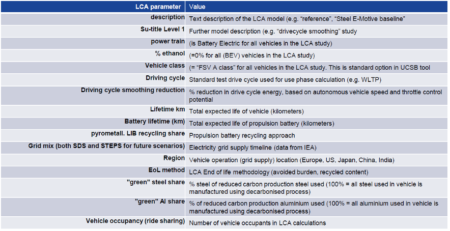
The analysis evaluated two reference/baseline conditions and nine SEM sensitivity studies, see Figure 4. These included alternative assumptions on LCA end-of-life modeling methodology, lifetime vehicle activity (and battery lifetime), alternative operational energy consumption sensitivities, sensitivities on the use of ‘green’ steel, and vehicle occupancy rates.
The accompanying pie chart shows the breakdown and contributions to the vehicle manufacture GHG for the baseline SEM scenario (2).
Life Cycle Assessment Conclusions
Based on the parameters outlined, applying LCA to SEM concept demonstrated the designs’ potential to reduce lifecycle greenhouse gas emissions by up to 86 percent compared to a present-day battery electric vehicle operating as a taxi.
This potential can be realized by adopting the following measures:
- Reducing vehicle production and manufacturing embedded emissions by utilizing 100 percent reduced carbon (“green”) steel
- Improving battery technology and increasing the use of renewable electricity in battery manufacturing; as well as increasing/improving battery recycling
- Ensuring the vehicle weight of autonomous vehicles is managed, and the potential weight reduction benefits realized and implemented. The SEM body structure and battery housing demonstrate good weight efficiency.
- Increasing the overall lifespan of the vehicle and battery. The fatigue and durability properties of AHSS can enable enhanced vehicle lifetime. The SEM battery design allows easy replacement of specific modules, enabling an overall extended battery life.
- Autonomous vehicle control smooths the driving cycle. The vehicle acceleration and deceleration rates can be optimized to match the driving conditions and road topography, reducing energy consumption and subsequent GHG emissions.
- Increasing passenger occupancy rates to at least three per vehicle via MaaS.
The projected net GHG emissions for the SEM vehicle operating with the flexibilities described above already represent a significant reduction when compared to the current baseline.
Achieving net zero emissions would require additional measures like offsetting manufacturing impacts (e.g., through compensatory credits from atmospheric carbon capture and storage) and transitioning to a 100 percent renewable electricity grid.
Moving Toward Net Zero
Taking a Life Cycle Assessment approach to the SEM concept demonstrates the possibilities for engineering future mobility vehicles that continue to move us closer to a net zero future. For more information about the Steel E-Motive program, download the engineering report here: https://bit.ly/SEM_Eng_Report
Thanks go to Russ Balzer for his contribution of this article to the AHSS Insights blog. As.technical director at WorldAutoSteel, he leads technical programs and oversees the organization’s work in research, modeling, and advocacy for Life Cycle Assessment in the automotive sector. An LCA Certified Professional through the American Center for Life Cycle Assessment (ACLCA), he also acts as the WorldAutoSteel liaison to the worldsteel LCA Expert Group.


