Laser Welding
This article is a summary of the paper entitled, “IMPROVEMENT OF DELAYED CRACKING IN LASER WELD OF AHSS AND 980GEN3 STEELS”, by Linlin Jiang, Kyle Kram, and Chonghua Jiang.L-62
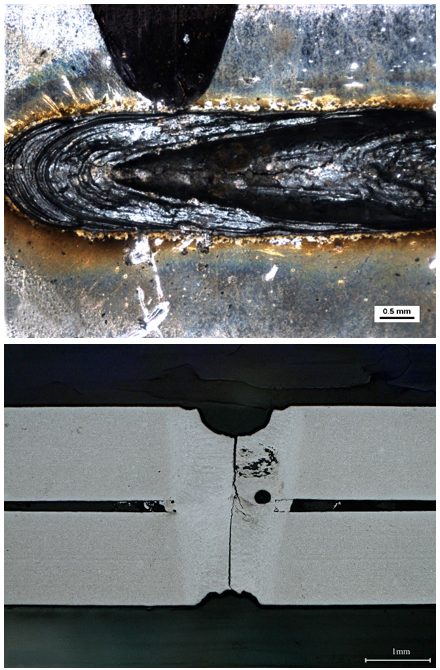
Researchers from AET Integration, Inc. worked on developing welding techniques that mitigated delayed cracking issues when laser welding Advanced High-Strength Steels (AHSS) and 3rd Gen AHSS. Stitch welds are most likely to have delayed cracking issues therefore the test specimen were cross tension samples with stitch welds. The test was run with ten specimens for each material with the same parameters. The specimen were visually inspected after welding in intervals from 30 min to 12 hours for 48 hours. The specimen were then inspected using X-ray analysis, cross-sectioning, and scanning electron microscope (SEM) analysis. Cracks were observed in the weld schedules used in Figure 1 and 2, and no cracking was observed in the welding schedules developed by researchers as seen in Figure 3 and 4 by altering parameters such as laser power, travel speed, beam oscillation, and defocusing techniques. The techniques are currently patent-pending and were not discussed in the research paper. Further validation tests on 3rd Gen steels is expected in the future.
Figure 1: Delayed Crack in Weld of Material A. (Top) Crack from top surface, (Bottom) Cross Section of Crack.L-62
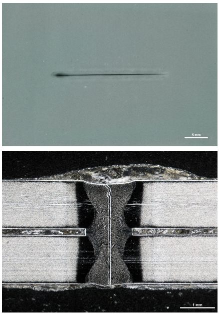
Figure 6: Delayed Cracking in Weld of Material B, (Top) X-ray, (Bottom) Cross section of crack.L-62
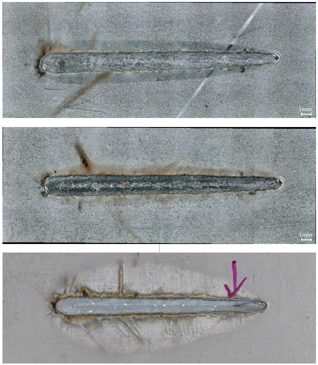
Figure 3: Examples of Visual Inspection Photographs. (Top) Top surface, Material A, (Middle) Top surface, Material B, (Bottom) Top surface, Material C.L-62
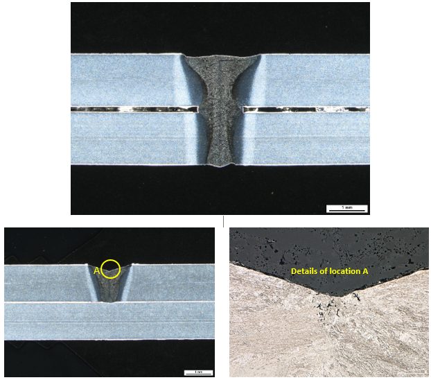
Figure 4: Examples of Cross Section Photographs. (Top) Cross section of weld center, Material A; (Bottom) Cross section of weld crater, Material A.L-62
Citations
Citation:
L-62. Linlin Jiang, Kyle Kram, and Chonghua Jiang, “IMPROVEMENT OF DELAYED CRACKING IN LASER WELD OF AHSS AND 980GEN3 STEELS”, AWS Sheet Metal Welding Conference XIX, Livonia, Mich., Nov. 2021.
Laser Welding
This article summarizes the findings of a paper entitled, “Hot cracking investigation during laser welding of high-strength steels with multi-scale modelling approach”, by H. Gao, G. Agarwal, M. Amirthalingam, M. J. M. Hermans.G-4
Researchers at Delft University of Technology (TU Delft) in The Netherlands and Indian Institute of Technology Madras in India attempted to model Hot Cracking susceptibility in TRIP and DP steels. For this experiment, TRIP and DP steels are laser welded and the temperatures experienced are recorded with thermocouples at three positions. Temperatures experienced during welding are measured and used to validate a finite element model which is then used to extract the thermal gradient and cooling rate to be used as boundary conditions in a phase field model. The phase field model is used to simulate microstructural evolution during welding and specifically during solidification. The simulation and experimental data had good agreement with max temperature deviation below 4%.
Summary
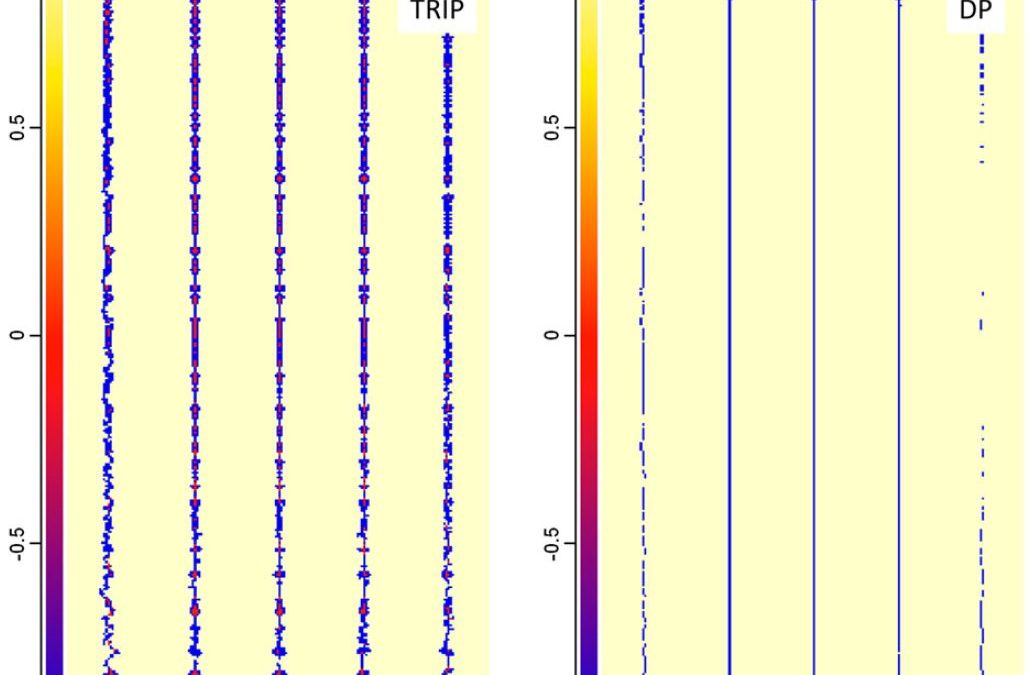
Referencing Figure 1 (Figure 6 in the original paper) which shows the microstructure where the dendritic tips meet the wel, centerline, it is observed that TRIP steels reach a solid fraction of 93.7% and DP steels reach a solid fraction of 96.3% meaning that TRIP steels have a larger solidification range than the DP steels. Figure 8 shows the phosphorus distribution where the dendritic tips reach the weld centerline. TRIP steels show a concentration of up to 0.55 wt-% where segregation occurs compared to the original composition of 0.089 wt-%. DP steels show a max of 0.06 wt-% which is significantly lower than the TRIP steels. In addition to phosphorus, Al is seen in high concentration in TRIP steels which contributes to the broder solidification range. A pressure drop is the last factor contributing to the Hot Cracking observed in TRIP steels(figure 2). The pressure drop is due to a lack of extra liquid feeding in the channels and forms a pressure difference from the dendrite tip to root. The pressure drop in TRIP steels is calculates to 941.2 kPa and 10.2 kPa in DP steels. The combination of element segregation, pressure drop, and thermal tensile stresses induced during laser welding results in a higher Hot Cracking susceptibility in TRIP steels as compared to DP steels.
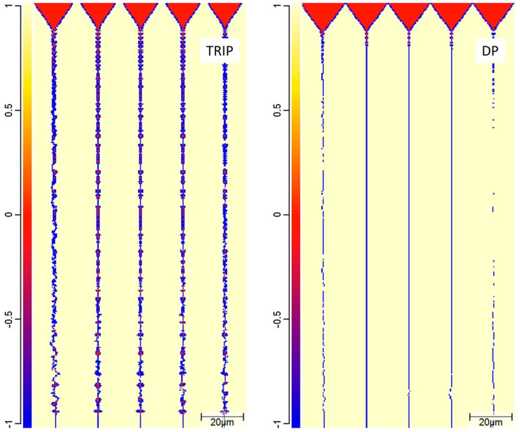
Figure 1: Phase distributions in the TRIP and the DP steel when the dendritic tips reach the weld centreline.G-4
![Tube Forming]()
Tube Forming
Manufacturing precision welded tubes typically involves continuous roll forming followed by a longitudinal weld typically created by high frequency (HF) induction welding process known as electric resistance welding (ERW) or by laser welding.
Tubular components can be a cost-effective way to reduce vehicle mass and improve safety. Closed sections are more rigid, resulting in improved structural stiffness. Automotive applications include seat structures, cross members, side impact beams, bumpers, engine subframes, suspension arms, and twist beams. All AHSS grades can be roll formed and welded into tubes with large D/t ratios (tube diameter / wall thickness); tubes having 100:1 D/t with a 1mm wall thickness are available for Dual Phase and TRIP grades.

Figure 1: Automotive Applications for Tubular Components.A-35
As roll formed and welded tubes are used with mounting brackets and little else in some Side Intrusion Beams (Figure 2), or they can be used as a precursor to hydroforming, such as the Engine Cradle shown in Figure 3.

Figure 2: Side intrusion beams made from a welded tube with mounting brackets.S-34

Figure 3: The stages of a Hydroformed Engine Cradle: A) Straight Tube, B) After bending; C) After pre-forming; D) Hydroformed Engine Cradle. S-35
The processing steps of tube manufacturing affect the mechanical properties of the tube, increasing the yield strength and tensile strength, while decreasing the total elongation. Subsequent operations like flaring, flattening, expansion, reduction, die forming, bending and hydroforming must consider the tube properties rather than the properties of the incoming flat sheet.
The work hardening, which takes place during the tube manufacturing process, increases the yield strength and makes the welded AHSS tubes appropriate as a structural material. Mechanical properties of welded AHSS tubes (Figure 4) show welded AHSS tubes provide excellent engineering properties. AHSS tubes are suitable for structures and offer competitive advantage through high-energy absorption, high strength, low weight, and cost efficient manufacturing
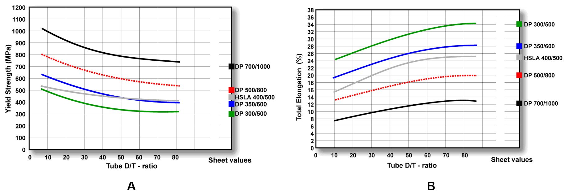
Figure 4: Anticipated Properties of AHSS Tubes; A) Yield Strength, B) Total Elongation.R-1
The degree of work hardening, and consequently the formability of the tube, depends both on the steel grade and the tube diameter/thickness ratio (D/T) as shown in Figure 5. The degree of work hardening influences the reduction in formability of tubular materials compared with the as-produced sheet material. Furthermore, computerized forming-process development utilizes the actual true stress-true strain curve of steel taken from the tube, which is influenced by the steel grade, tube diameter, and forming process.

Figure 5: Examples of true stress – true strain curves for AHSS tubes made from Dual Phase Steel with 590 MPa minimum tensile strength.A-36
Bending AHSS tubes follows the same laws that apply to ordinary steel tubes. Splitting, buckling, and wrinkling must all be avoided. As wall thickness and bend radius decrease, the potential for wrinkling or buckling increases.
One method to evaluate the formability of a tube is the minimum bend radius. An empirically derived formulaS-36 for the minimum Centerline Radius (CLR) considers both tube diameter (D) and total elongation (A) determined in a tensile test with a proportional test specimen, and assumes tube formation via rotary draw bending:
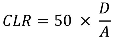
The formula shows that a bending radius equal to the tube diameter (1xD) requires a steel with 50% elongation. Successfully bending low elongation material needs a greater bend radius. Consider, for example, a dual phase steel grade where the elongation of a sample measured off the tube is 12.5%. Here, the minimum bend radius is 4 times the tube diameter. The tube bending method, the use and type of mandrels, and choice of lubrication may all affect the CLR.
The engineering strain on the outer surface can be estimated as the tube diameter (D) divided by twice the Centerline Radius (CLR):
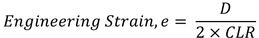
For example, if you are bending a 40 mm diameter tube around a centerline radius of 100mm, the engineering strain on the outer surface is approximately 40/[2*100] = 20%. As a rough estimate, successful bending requires the tube to have a minimum elongation value from a tensile test in excess of this amount. Otherwise, a larger radius or modifications to the forming process is needed.
Springback is related to the elastic behavior of the tube. Yield strength variation between production batches can lead to variation in the amount of springback. A rule of thumb is that a variation of ± 10 MPa in yield strength causes a variation of approximately ± 0.1° in the bending radius. In addition, a high frequency weld which is harder and stronger than the base material causes a maximum of approximately ± 0.1° variation in bending radius.S-36
The bending behavior of tube depends on both the tubular material and the bending technique. The weld seam is also an area of non-uniformity in the tubular cross section, and therefore influences the forming behavior of welded tubes. The recommended procedure is to locate the weld area in a neutral position during the bending operation.
Figures 6 and 7 provide examples of the forming of AHSS tubes. The discussion on Tailored Products describes tailored tubes, which may be further hydroformed.

Figure 6: DP steel bent to 45 degrees with centerline bending radius of 1.5xD using booster bending. Steel properties in the tube: 610 MPa yield strength, 680 MPa tensile strength, 27% total elongation. R-1

Figure 7: Hydroformed Engine Cradle made from a dual phase steel welded tube by draw bending with centerline bending radius of 1.6xD and a bending angle greater than 90 degrees. Steel properties in the tube: 540 MPa yield strength, 710 MPa tensile strength, 34% total elongation. R-1
Key Points
- Due to the cold working generated during tube forming, the formability of the tube is reduced compared to the as-received sheet.
- The work hardening during tube forming increases the YS and TS, thereby allowing the tube to be a structural member.
- Successful bending requires aligning the targeted radii with the available elongation of the selected steel grade.
- The weld seam should be located at the neutral axis of the tube, whenever possible during the bending operation.


