K-7
Citation:
K-7. N. Kardes Sever, “Investigation of Lubrication and Springback in Forming of Draw Quality and Advanced High Strength Steels,” Dissertation, The Ohio State University, 2012.
K-7. N. Kardes Sever, “Investigation of Lubrication and Springback in Forming of Draw Quality and Advanced High Strength Steels,” Dissertation, The Ohio State University, 2012.
S-7. Society of Automotive Engineers (SAE) International, SAE J 2575, “Standardized Dent Resistance Test Procedure,” 2015, doi.org/10.4271/J2575_201504.

Tool and die wear occurs due to the friction produced from the contact between the sheet metal and the tooling surface. Damage to the die surface can cause a gradual loss of tooling material, and scoring or burnishing damage to the sheet metal surface may be stress risers leading to premature failure in formed parts.
Impacting tool wear are the die material, strength of sheet metal, contact pressure, surface finish of the sheet and tooling, sliding velocity, temperature, coating of the die, and lubrication used. Advanced steel grades, where work hardening during stamping further increases the strength of an already high strength product, may result in additional die wear. Die wear beyond a critical point calls for replacement of the current die, impacting turnaround times and to production losses.
New die materials and better die coatings exist which minimize the impact of excessive tooling wear when forming AHSS. These new die materials include wrought and cast tool steels as well as powder metallurgy tool steels, which retain hardness without compromising the toughness of the material. Furthermore, hard material coatings and nitriding can improve the tribological properties of die surfaces.
Most tool materials for sheet metal forming are cast iron, cast steel, or tool steels.N-12 Cast iron grades used for stamping applications are gray cast irons (like G2500, G25HP and G3500) and pearlitic ductile irons (D4512, D6510, and D7003, among others). Cast steel grades include S0030, S0050A, S7140, and S2333. Tool steels include TD2 (a high wear / low shock resistant tool steel), TS7 (a high shock / low wear resistant tool steel) and TA2 (a balanced medium wear / medium shock resistant tool steel). These designations come from Reference NAAMS, with other designations in Citations A-37, A-38, I-11, J-7, J-8, J-9 Many of these designations overlap and represent the same or highly similar product. For example, ASTM A681 D2, JIS G4404 SKD11, and ISO 4957 X153CrMoV12 cover the same alloy tool steel.
In general, existing tool and die shop procedures to select the appropriate die material are applicable to select dies made to stamp Advanced High Strength Steels. However, the considerably higher strength level of these grades exerts proportionally increased load on the die material. AHSS grades might reach hardness values 4 to 5 times higher than mild steel grades. This is partially due to the microstructure of the sheet metal itself since some grades achieve higher strength from the microstructural phase martensite. Some martensitic grades (MS) have a tensile strength higher than 2000 MPa. This strength level corresponds to Rockwell C values higher than 57, meaning that the sheet metal hardness is approaching the tooling hardness.
The higher forces required to form AHSS require increased attention to tool specifications. The three primary areas are:
The accepted amount of wear/galling between maintenance periods is a key factor in determining the performance requirements of draw dies, punches, and other tooling components. Some of the key elements that affect the die material specification include:
Counteracting the increased applied load required to form AHSS grades is a potential reduction in sheet thickness. This thickness reduction leading to lighter weight parts is one of the key drivers promoting expanded use of Advanced High Strength Steels. Unfortunately, the reduced thickness of the steel increases the tendency to wrinkle. Suppressing these wrinkles requires higher blankholder forces. Any formation of wrinkles will increase the local load and accelerate the wear effects. Figure 1 shows a draw die with severe die wear due to excessive wrinkling on a DP980 part. It is not uncommon to replace these high wear areas with a more durable tool steel insert to minimize this type of excessive wear condition.

Figure 1: Draw die with significant wear due to excessive wrinkling on a DP980 part. S-45
Surface treatments and coatings help increase tool life and reduce friction. Flame or induction hardening heat treatments, nitriding, and chrome plating are common surface treatment techniques used. However, each of these can fail under the high contact pressure that is present when stamping advanced high strength steels. Coating the inserts adds additional wear and friction benefits.
Many surface hardening options exist which improve the wear resistance.A-7 Carbon content limits the achievable surface hardness with either flame hardening or induction hardening. Tools hardened with either approach must be quenched after heating, which increases the risk of distortion. Laser beam hardening relies on the high thermal conductivity of underlying base tool steel to self-quench, which reduces the magnitude of distortion. Further minimizing distortion: the energy input in laser beam hardening is approximately 10% of flame hardening.
Carbon and nitrogen increase the strength and hardness of sheet steels. Similarly, carburizing and nitriding tool steels create a hard, wear-resistant surface layer. Carburizing is done at a higher temperature, which carries the risk of distortion. Nitriding takes primarily one of two forms: gas nitriding and plasma (ion) nitriding. Ion nitriding is faster than gas nitriding, accomplished at a lower processing temperature, and minimizes the thickness of the brittle “white layer.” A-39
Chrome plating of tools and dies has been an option to increase wear resistance, but may exhibit microcracking. Environmental concerns further limit its use. In addition, studies show that is it not the best option for tools used to form advanced high strength steels.Y-6
A high hardness, low friction coating results in a wear resistant surface that lowers the risk for galling. Coatings include titanium nitride (TiN), titanium carbide (TiC), titanium carbonitride (TiCN), titanium aluminum nitride (TiAlN) and chromium nitride (CrN). Common application methods are physical vapor deposition (PVD), chemical vapor deposition (CVD), and thermal diffusion (TD).
The strength of metallurgical bonds produced in the CVD and TD processes are greater than physical bond associated with the PVD approach. However, application of CVD and TD coatings occurs at around 1000 degrees C, which is likely in the austenite region of the tool steel. This high temperature can soften the die, which then necessitates a subsequent rehardening process, and may also cause dimensional distortion. For these reasons, several global automakers specify only PVD coatings.
The benefits of PVD coatings in reducing galling are apparent in Figure 2, which compares a cut edge after blanking of 200,000 parts of CR 500Y/800T-DP. Use of cutting steels with a PVD-applied TiAlN coating results in a cleaner, more uniform edge.
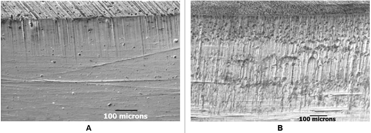
Figure 2: PVD-applied TiAlN-coated cutting steel (image A) reduces galling compared with an uncoated cutting steel (image B). Edges are shown after 200,000 parts produced from CR 500Y/800T-DP. T-20
Since coatings may crack, it is important that the substrate has sufficient hardness/strength to avoid even the slightest plastic deformation of the tool surface. Therefore, the recommended practice is to perform an initial surface hardening treatment, typically flame or induction hardening followed by ion nitriding, to develop substrate hardness and strength before applying the coating. Surface roughness must be as low as possible before coating, with average surface roughness (Ra) values below 0.2 μm recommended. This roughness level approximates a 600-grit sandpaper finish.
Considering the high cost of coated tool steels, a recommended approach is to construct large forming tools from relatively inexpensive and soft materials, such as cast iron or low-grade tool steel. Locations subject to severe wear are candidates for inserts of high-grade tool steels with an appropriate coating engineered for the application.
Ceramic tool inserts have extreme hardness for wear resistance, high heat resistance, and optimum tribological behavior, but have poor machinability and severe brittleness. Potentially offsetting the higher cost are reduced maintenance and increased productivity. While not commonly used, the ceramic tool inserts offer a possible solution to high interface loading and wear.
Select tool steel inserts for forming dies according to the sheet metal and the forming severity. These inserts should have a surface coating when processing DP 350/600 and higher grades. Initial tryout should be completed before coating, so that die adjustments and springback compensation efforts do not lead to removal of the newly applied coating. Allow for tooling recuts during this tryout loop to ensure the resulting tool has sufficient mass and stiffness. Different friction and metal flow conditions should be expected between the initially uncoated and the ultimately coated tool steels.
The optimal surface treatment may increase upfront cost, but will reduce the rework and die maintenance cost over the life of the die. Shown in the top two lines of Figure 3 are the benefits of plasma ion nitriding a flame hardened graphite-bearing cast iron tool (GGG70L) when forming 1 mm thick electrogalvanized dual phase steel. The bottom two lines show the effect on AISI D2 (DIN 1.2379 or JIS SKD11), highlighting only minimal tooling wear over the 5000 parts evaluated.

Figure 3: Plasma ion nitriding leads to reduced tool wear. GGG70L is a flame hardened spheroidal graphite-bearing cast iron and DIN 1.2379 is AISI D2 or JIS SKD11 cold work tool steel.T-11
Figure 4 compares the surface appearance of the same tool steel with different coatings. On the left is a chrome-plated tool which exhibited adhesive and abrasive wear, and ran for only 50,000 parts. Shown on the right is an ion nitrided tool steel which was chromium nitride coated using PVD, and produced more than 1.2 million parts.

Figure 4: Tool steel surface. Left image: Chrome plated, failed after 50,000 parts; Right image: Ion nitride tool steel, chromium nitride PVD coating, produced more than 1.2 million parts. J-10
Heat produced from stamping AHSS grades interacts with the tool material and coating, which may impact friction and metal flow. 1mm thick hot dip galvannealed CR340Y/590T-DP-GA was evaluated in a laboratory set-up.S-46 Initially at room temperature, die surface temperature increased to 65 °C (150 °F) after 10 cycles of passing this DP590 grade across a tool radius and significant zinc powdering occurred. Less powdering occurred with the use of a die coolant. Cooling the dies also helped to reduce the surface scoring and associated friction [Figure 5].
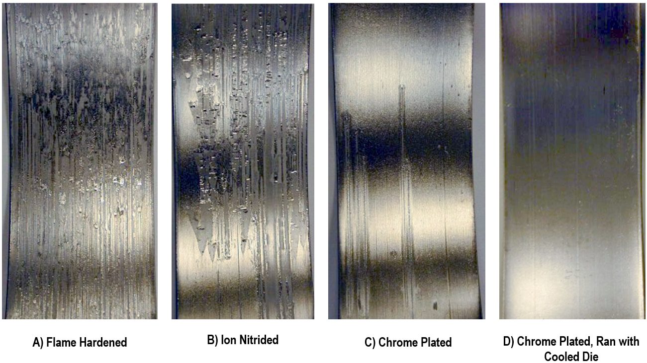
Figure 5: Coatings and Die Coolant on D2 Tool Steel Reduce Scoring and Friction with galvannealed dual phase steel. A) Flame Hardened; B) Ion Nitrided; C) Chrome Plated; and D) Chrome Plated with die coolant.S-46
Selection of tool steels for cutting, trimming, and punching tools have similar considerations as forming tools. The base tool steel must have excellent chipping and cracking resistance. Coatings will reduce tool wear. Hardening of the substrate prior to coating will minimize failure due to plastic deformation of the substrate. Coatings reduce the severity of the shock wave produced when cutting advanced high strength steels. See the Cutting / Blanking / Shearing / Trimming page for more information.
It is not advisable to use only one tooling solution for all Advanced High-Strength Steels. One study showed that die material and coating methods used in large volume production of steel grades up to and including those with 980 MPa minimum tensile strength were not suitable for forming a grade with 1180 MPa minimum tensile strength.W-18 Furthermore, this study recommends avoiding die materials such as ductile iron and low alloy cast steel when stamping 1180 grade steels.
In addition to selecting the correct die material, it must be processed appropriately. Figure 6 shows the effects of proper heat treatment when stamping a dual phase steel with 980MPa minimum tensile strength.S-45 This same study showed that a PVD coated tool performed best when forming a DP steel without a galvanized coating, yet the PVD coating led to significant zinc buildup when forming a galvanized DP steel. An ion nitride tool coating worked best for galvanized steels.
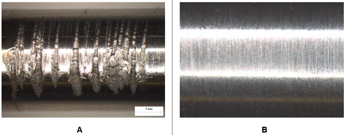
Figure 6: Effect of Heat Treatment on Tools to Stamp Dual Phase Steel. Image A) No heat treatment leads to wear; Image B) Proper heat treatment results in a surface without damage.S-45
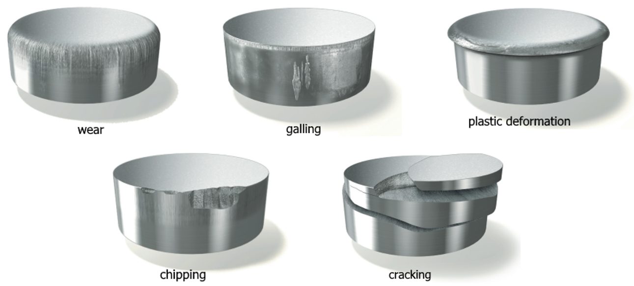
There are five main types of cold work failure modes involving tool steels – wear, plastic deformation, chipping, cracking, and galling. There is also interaction between these failure modes. Figure 7 shows examples of these failure modes.T-20, U-7
Wear is damage to the tooling surface resulting in material loss and is related to the tooling material hardness, and the type, volume, and distribution of hard particles like oxides or carbides. Wear can also be related to material type and process conditions and involves sliding contact between the tooling and the material. There are two types of wear: abrasive and adhesive.
Abrasive wear occurs when hard particles forced into a surface during the sliding contact leads to removal of metal from the tool steel. Tool steel properties promoting abrasive wear resistance include high hardness of the tool steel and of the carbides, as well as a high volume of large carbides. However, the high hardness targeted for wear resistance makes the material sensitive to notches. Large carbides act as crack initiators, increasing the risk of fatigue cracking.
Adhesive wear occurs with material transfer from one metal surface to another. The friction and heat generated as the sheet metal slides across the tool surface results in micro-welding between the asperities (peaks) on each surface. Failure of these micro-welds occurs with continued relative motion between the two surfaces, with small fragments torn from the weaker side surface and adhering to the other surface. The material ripped out of the tool steel will occasionally stick to the sheet metal surface. With continued metal motion, these pieces may score and damage the tool steel surface resulting in a combination of adhesive and abrasive wear known as mixed wear.
Galling is a physical/chemical adhesion of the sheet metal to the tool surface. The severity of the galling depends on the surface finish and chemical composition of the material and the tool steel and involves the friction and sliding contact between the tooling and the material. Galling, abrasive wear, and adhesive wear are related, and can be minimized through the use of proper surface treatments or coatings on top of a tool steel with high hardness (Figure 8).

Figure 8: Adhesive wear of the tooling leads to abrasive wear scratches on the DP600 sheet surface. Continued abrasive wear leads to galling of the sheet surface. Higher magnification images are shown on the bottom. G-18
Plastic deformation occurs when the stress from contact with the sheet metal exceeds the compressive yield strength of the tool material. A high hardness tool steel helps to avoid this damage.
Chipping occurs when the operating stress levels exceed the fatigue strength of the tool steel, typically found at sharp edges. Microcracks initiate in the high contact area of the tool surface, propagate, and ultimately result in pieces chipping out along edges or at corners. Chipping may initiate in areas affected by adhesive wear. Here, microcracks can nucleate, deepen, and spread, leading to a fatigue failure. A tool steel with high ductility has good chipping resistance, since microcrack initiation and propagation are more difficult.
Cracking occurs when the operating stress levels exceed the fracture toughness of the tool material. Crack formation occurs in the presence of stress concentrators, like grinding and machining marks or design features such as sharp corners or radii. Once the crack forms, unstable crack propagation leads to failure. Microstructural toughness promotes good cracking resistance, as does low hardness. However, low hardness has a detrimental effect on the resistance to the other failure mechanisms and is not normally a good solution.
Higher strength steels lead to greater demands on the wear resistance and mechanical strength of the tool material. Forming operations require high wear and galling resistance and compressive strength. Cutting operation require a combination of high wear resistance, high galling resistance, high compressive strength, high chipping, and total cracking resistance.
Tool materials must balance compressive strength and toughness with resistance to wear, thermal, and mechanical stresses.
Conventional highly alloyed tool steels are produced from large ingots. The slow solidification leads to microstructural segregation, forming large carbide networks which turn into carbide stringers after processing. These networks are beneficial for wear resistance, but reduces fatigue strength and toughness.
Alternate approaches minimizing segregation reduces these concerns. Two such production methods are electroslag remelting and powder metallurgy.T-20
Electroslag remelting (also known as electroslag refining, ESR) is a progressive melting process used to produce porosity-free ingots of uniform chemistry. Under a protective atmosphere, only a small portion of the ingot is liquid at any one time, and solidification occurs in a controlled manner. This processing approach results in tool steels with increased cleanliness, smaller carbides, and improved ductility and fatigue properties. It is relatively expensive, leading to its use in some specialized tool steel applications.
Rather than slowly solidifying in a large ingot, powder metallurgy (PM) production involves first atomizing a stream of molten metal using a high pressure inert gas, resulting in droplets that rapidly solidify into powder. Segregation is typically a fraction of the powder diameter, which is on the order of 100 μm. Hot isostatic pressing (HIPing) consolidates the collected powders, which is subsequently rolled or forged in a similar manner used for ingots.
Without the concern of macro-segregation or large carbides, the PM approach allows for manufacturing of more highly alloyed tool steels than is possible with conventional ingot metallurgy. Here, the carbides are smaller and more evenly distributed even compared with the ESR approach, leading to a balance of wear resistance and fatigue life. PM tool steels have enhanced resistance to abrasive wear, adhesive wear, chipping, and cracking. Coatings improve galling resistance.
Metal stampers and die shops experienced with mild and HSLA steels often have problems making parts from AHSS grades. The higher initial yield strengths and increased work hardening of these steels can require as much as four times the working loads of mild steel. Some AHSS grades also have hardness levels approaching the dies used to form them.
The higher stresses required to penetrate higher-strength materials require increased punch-to-die clearances compared to mild steels and HSLA grades. Why? This clearance acts as leverage to bend and break the slug out of the sheet metal. Stronger materials need longer levers to bend the slug. The required clearance is a function of the steel grade and tensile strength, and sheet thickness.
Increasing cutting clearance can result in punch cracking and head breakage due to higher snapthrough loads and reverse-unloading forces within the die. Adding shear angles to the punch face helps reduce punch forces and reverse unloading.
Tight cutting clearances increase the tendency for die galling and chipping. The severity of galling depends on the surface finish and microstructure of both the tool steel and work material. Chipping can occur when process stresses are high enough to cause low-cycle fatigue of the tooling material, indicating that the material lacks toughness.
Tempering of tools and dies represents a critical heat-treatment step and serves more than one purpose, but of primary concern is the need to relieve residual stresses and impart toughness. Dies placed in service without proper tempering likely will experience early failure.
Dies made from the higher-alloy tool-steel grades (D, M or T grades) require more than one tempering step. These grades contain large amounts of retained austenite and untempered martensite after the first tempering step and require at least one more temper to relieve internal stresses, and sometimes a third temper for even greater toughness.
Unfortunately, heat treatment remains a “black-box” process for most die shops and manufacturing companies, who send soft die details to the local heat treat facility, with hardened details returned. A cursory Rockwell hardness test may be conducted at the die shop when the parts return. If they meet hardness requirements, the parts usually are accepted, regardless of how they may have been processed—a problem, as hardness alone does not adequately measure impact toughness.
Consider this scenario: An automotive structural part has been in production for years as a conventional high strength steel with a minimum yield strength of 280 MPa, CR280Y350T-LA. In order to meet increasing global safety regulations, the automaker converts the part to a dual phase steel, CR340Y590T-DP. Even though these grades have relatively close minimum yield strength levels as produced at the steel mill, dual phase steels have excellent work hardening characteristics and are bake hardenable. These are among the reasons for their favorable response in crash events in comparison to HSLA grades.
The stamping location attempted to do a direct swap, substituting the DP steel for the HSLA grade with no changes to the part or process. Immediately after the grade change, scrap rates increased significantly. The failures were all determined to be local formability edge fractures; investigation revealed that the edge of the configured blank remained as the final product edge which split during forming and subsequent flanging. Examination of the edge revealed a burr as well as a non-uniform cut edge appearance. The tool showed signs of chipping.
Issues found, along with corrective actions:
Making these changes to accommodate the new grade eliminated scrap from this process.
Multi-phase steels are complex to cut and form, requiring specific tooling materials. The tooling alloys which have been used for decades, such as D2, A2 or S7, are reaching their load limits and often result in unacceptable tool life. The mechanical properties of the sheet steels achieve tensile strengths of up to 1800 MPa with elongations of up to 40%. Additionally, the tooling alloys are stressed by the work hardening of the material during processing.
The challenge to process AHSS quickly and economically makes it necessary for suppliers to manufacture tooling with an optimal tool steel selection. The following case study illustrates the tooling challenges caused by AHSS and the importance of proper tool steel selection.
A manufacturer of control arms changed production material from a conventional steel to an Advanced High-Strength Steel (AHSS), HR440Y580T-FB, a Ferrite-Bainite grade with a minimum yield strength of 440 MPa and a minimum tensile strength of 580 MPa. However, the tool steels were not also changed to address the increased demands of AHSS, resulting in unacceptable tool life and down time.
According to the certified metal properties, the 4 mm thick FB 600 material introduced into production had a 525 MPa yield strength, 605 MPa tensile strength, and a 20% total elongation. These mechanical properties did not appear to be a significant challenge for the tool steels specified in the existing die standards. But the problems encountered in production revealed serious tool life problems.
To form the FB 600 the manufacturer used D2 steel. D2 was successful for decades in forming applications. This cold work tool steel is used in a wide variety of applications due to its simple heat treatment and its easily adjustable hardness values. In this case, D2 was used at a hardness of RC 58/60.
While tools manufactured from D2 can withstand up to 50,000 load cycles when forming conventional steels, these particular D2 tools failed after only 5,000 – 7,000 cycles during the forming of FB 600. The first problems were detected on a curl station where mechanical overload caused the D2 tools to break catastrophically, as seen in Figure 9 below. Since the breakage was sudden and unforeseeable, each failure of the tools resulted in long changeover times and thus machine downtime.

Figure 9: Breakage seen in control arm curl tool made from D2, leading to premature failure. Conversion to a PM tool steel having higher impact resistance led to 10x increase in tool life.M-20
Since the cause of failure was a mechanical breakage of the tools, a tougher alternative was consequently sought. These alternatives, which included A2 and DC53® (a registered trademark of International Mold Steel) were tested at RC 58-60 and unfortunately showed similar tool life and failures.
Metallurgical analysis indicated that the failure resulted from insufficient impact strength of the tool steel. This was caused by the increased cross-cut that the work-hardened AHSS exerted on the curl. As an alternative material, a cold work steel with a hardness of 58-60, a tensile strength of about 2200 – 2400 MPa and high toughness was sought. These properties could not be achieved with conventional tool steels. The toolmaker used a special particle metallurgy (PM) tool steel to obtain an optimum combination of impact strength, hardness and wear resistance.
Particle metallurgy (PM) tool steels, due to their unique manufacturing process, represent improvements in alloy composition beyond the capabilities of conventional tool steels. Materials with a high alloy content of carbide formers such as chromium, vanadium, molybdenum and tungsten are readily available. The PM melting process ensures that the carbides are especially fine in particle size and evenly distributed (reference Table 1). This process results in a far tougher tool steel compared to conventional melting practices.

Table 1: Elemental Composition of Chosen Tool Steel
The manufacturer selected Z-Tuff PM® to be used at a hardness of RC 58-60. Employing the identical hardness as the conventional cold work steel D2, a significant increase in impact strength (nearly 10X increase as measured by un-notched Charpy impact values) was realized due to the homogeneous microstructure and the more evenly distributed precipitates. This positive effect of the PM material led to a significant increase in tool life. By switching to the PM tool steel, the service life is again at the usual 40,000 – 50,000 load cycles. By using a steel with an optimal combination of properties, the manufacturer eliminated the tool breakage without introducing new problems such as deformation, galling, or premature wear.
AHSS creates tooling demands that challenge the mechanical properties of conventional tool steels. Existing die standards may not be sufficient to achieve consistent and reliable performance for forming, trimming and piercing AHSS. Proper tool steel grade selection is critical to ensuring consistent and reliable tooling performance in AHSS applications. Powder metallurgical tool steels offer a solution for the challenges of AHSS.
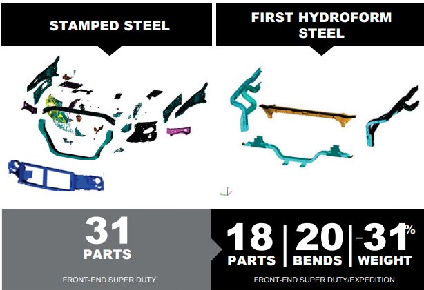
Tube hydroforming creates complex shapes by using internal pressure to expand a tube against a die cavity. Frame rails, engine cradles, roof rails and bows, instrument panel beams, cross members, pillars, and seat frames are among the parts created using hydroforming. Benefits of this approach can include part consolidation, weight reduction, improved stiffness and strength, tighter dimensional tolerances, fewer secondary operations, and reduced cost compared with conventional stamping and welding approaches.
These benefits are highlighted in a truck front end structure shown in Figure 1, where hydroforming allowed for consolidation of 31 parts into 18, and resulted in a 31% weight reduction. M-67
Automotive body structures have incorporated hydroformed parts for several years, with recent vehicles using AHSS grades to improve crash energy management and impact performance. Some specific examples:
The hydroformed A-Pillar on the 2015 Mustang Convertible (Figure 2) distributes impact loads to the windshield header and the hinge pillar.M-16
Hydroforming facilitates part consolidation and weight reduction relative to a stamped truck front end structure.M-67

Figure 2: 2015 Mustang Convertible: A-Pillar.M-16
The Door-to-Roof Support on the 2016 Nissan Titan XD (Figure 3) extends from the rocker/hinge pillar through the A-pillar and almost to the B-Pillar. Hydroforming this part from a Dual Phase Steel with 980MPa minimum tensile strength allowed for 25% section strength improvement allowing for thinner material at the same performance level. T-18, L-18
The hydroformed Upper Load Beams of the 2017 Chrysler Pacifica (Figure 4) saved 1.8 kg per vehicle compared with a conventional approach.T-19

Figure 4: 2017 Chrysler Pacifica: Upper Load Beams.T-19
Each of the two hinge pillars on the 2019 Jeep Wrangler (Figure 5) contain 2 hydroformed tubes made from TRIP 400/690.B-8

Figure 5: 2019 Jeep Wrangler: Hinge Pillars.B-8
Tube hydroforming, as the name suggests, starts with a linear-welded tube, produces either with high frequency induction welding or laser welding. The tube is then bent to the general shape, and a pre-forming operation helps to put steel in the optimal position. After placing the preformed tube in the hydroforming die, end-plugs create a seal for subsequent internal pressurization. Figure 6 shows the changes to tube shape along the process of producing the hydroformed roof rails from DP800/1000 for the 2015 Ford Edge.H-13

Figure 6: Shape evolution to achieve a hydroformed roof rail from DP 800/1000.H-13
If the hydroforming process does not result in a change in the length of the pre-formed tube, then the only change is an increase in the local section diameter. This corresponds to a strain state of plane strain, which is the strain path associated with the greatest risk of cracks. Mounting the end-plugs on actuators allows for application of axial loads on the ends of the tube as the internal pressure changes. End feeding in this manner changes the strain state favorably, creating compression in the axial direction as the tube diameter stretches. With axial feeding, the strain state near the ends move to the left hand side of the Forming Limit Diagram, allowing for higher strains to be reached prior to failure – meaning that more complex shapes can be created. Away from the tube ends, the axial feeding has limited effect, so plane strain formability (the lowest point on the Forming Limit Curve) limits the product shape.
Formability is further limited compared with the incoming sheet, since the rolling, welding, sizing, bending, and pre-forming operations all decrease the available ductility prior to hydroforming. Understanding the effect of each operation which changes the strain and thickness in the tube allows for small process changes which may help to improve the amount of residual ductility for the subsequent tube hydroforming operation. The strains generated from each step results in the work hardening of the sheet steel, leading to an increase in strength and decrease in ductility.
Product and tool designs must account for these increased strengths and reduced formability parameters. The deformation available for the pre-form bend process and the subsequent hydroforming process will depend on the material selected, tube D/T ratio, tube manufacturing process, centerline radius of the pre-form bend, and the included angle of the bend. Tubes of higher strength AHSS will have limited elongation available. Avoid exceeding the available total elongation for bending limits or forming limits – especially in the work hardened areas of the pre-form bends. Refer to Figure 4 in the Tube Bending article for anticipated elongation values for several illustrative high strength steels formed into tubes of various D/T ratios.
The hydroforming process for tubes usually involves expanding the tube diameter from 3% to 30% depending on the design, materials selected and pressures available for forming. Tube production commonly utilizes one of three basic methods of hydroforming tubes, categorized by the internal pressure used for the expansion.
In high-pressure tube hydroforming, the tube is placed in the die and the die is closed. Pressurizing the tube now causes the metal to stretch as the circumference increases to conform to the inner circumference of the die – often with tight radii in corners and product features. Higher strength steels may be unable to expand sufficiently to fill the die geometry or create small radii without failure. Furthermore, high pressure could be necessary to obtain the correct geometry with minimum springback or fewer wrinkles compared to low-pressure hydroforming.
Low-pressure tube hydroforming begins with a tube whose circumference is slightly less than the final circumference of the finished geometry. Tube pressurization occurs after placing the tube in an open die, prior to closing. As the die closes, the circumference of the tube changes shape to conform to the closing die. The internal pressure is sufficient to prevent the tube from buckling during the shape change. A small circumference increase combined with a uniform wall thickness means that high strength and lower-formability metals can achieve tighter radii without failure. This low pressure process is suitable for tubes made from AHSS. This approach results in a change of the shape of the tube cross-section, rather than tube expansion.
A third process reduces the severity of circumferential expansion by using the end feeding approach previously described. Special end pistons push additional material into the die cavity from the tube end to provide more material for higher expansion of the tube circumference. This method of tube circumference expansion involves bi-directional strain. The end feeding is beneficial for hydroforming tubes from AHSS. Note that excessive end-feeding may increase the pressure required to form small corner radii.S-43
To assist with pre-production process and die design, computerized forming-process development is an excellent tool for examining the validity of applying different AHSS to potential part designs. However, proper inputs are critical: hydroforming tubes made from advanced high strength steels require highly developed forming limit curves generated which consider different tube D/T ratios, degrees of pre-form bend, and final geometrical shape. Each step as the straight tube is converted to a hydroformed part represents a non-linear strain path, which increases the importance of using the proper Forming Limit Curve. The FLC generated for the initial sheet steel will give a false indication of the available formability since it does not account for the impact of the forming steps prior to hydroforming.
An example of the material property changes from tube creation comes from Figure 7, which compares 1.88 mm thick mild steel (labeled as DDQ), HSLA 350/450, and DP 350/600 formed into a 76.2 mm (3 inch) diameter tube. Figure 7 shows the summary of average properties for the three steels. The much larger jump associated with tube forming of the dual phase steel grade is associated with the higher n-value of this product.

Figure 7: Strength Comparison on samples taken from the flat sheet and after tube forming.S-43
For trimming and piercing, the same general cautions utilized for stamped AHSS parts apply to hydroformed AHSS parts. Since Advanced High Strength Steels have higher tensile strength than conventional high-strength steels, engineering the trim tools to withstand higher loads is a requirement. Proper support for the trim stock during the trim operation will minimize edge cracking. Laser trimming, which is common for hydroformed parts, is still an excellent choice. However, the trimmed edge may see some hardening associated with the local heating and cooling from the laser beam.
In general, the same design guidelines that support hydroforming of conventional steels apply to AHSS. However, consideration of part function and the available elongation for forming is necessary during development of the part design and manufacturing processes.
The manufacturing industry is currently experiencing a significant transformation of digitalization, connectivity, and higher flexibility of the manufacturing process. Recently, several studies were conducted by different researchers and companies on developing more complicated control systems with new sensors and applying a machine-learning algorithm to analyze the collected data from the sensors. Therefore, an extensive literature review was conducted to address the applications of Industry 4.0 (sensor, process control, and forming equipment control) for sheet metal forming.
This article introduces the latest information and provides insight on how to practically implement newly introduced technologies and tools for industrial sheet metal forming processes to make the forming processes more efficient and robust.
Manufacturing processes have become more efficient and productive with help from smart machines, intelligent systems, and data analytics. This rapid change in manufacturing leads to a new industrial revolution, frequently called Industry 4.0.
Industry 4.0 has been defined as “a name for the current trend of automation and data exchange in manufacturing technologies. It includes cyber-physical systems, the Internet of things (IoT) and cloud computing and cognitive computing and creating the smart factory”.I-17
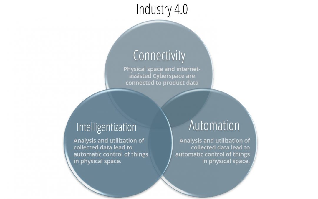
Three key factors — connectivity, intelligentization, and automation (Figure 1) — characterize this new industrial revolution. The combination of these factors changes conventional production to a more customized, flexible, and on-demand manufacturing production, creating significant technical challenges.Y-13 To overcome these challenges, the integration of the three key factors highlighted in Figure 1 becomes essential for the manufacturing industry.
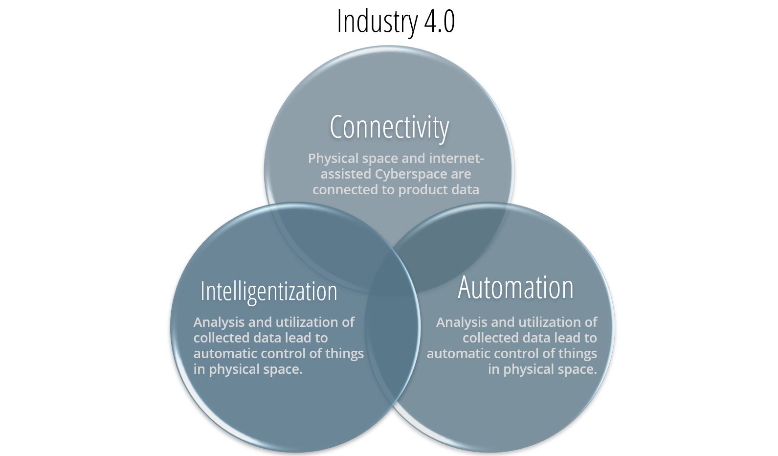
Figure 1: Key factors for Industry 4.0.Y-13
There is interest in the sheet metal industry on how to adopt Industry 4.0 into their legacy forming practices to significantly improve productivity and product quality. Figure 2 illustrates four important variables influencing the part quality: material properties, die friction response, elastic deflection of the tool, and press dynamic characteristics. These variables are usually difficult to measure or track during the production runs. When these variables significantly influence the part quality and the scrap rate increases, the operators manually adjust the forming press parameters (speed and pressure), lubricant amount, and tooling setup. However, these manual adjustments are not always possible or effective and can be costly for the increased part complexity. The use of new advanced high-strength and light-weight materials often escalates technical challenges associated with formability and robustness of the current forming process as well.

Figure 2: Important variables influencing the stamping quality.H-35
The ultimate vision for Industry 4.0 in sheet metal forming is an autonomous forming process with maximum process efficiency and minimum scrap rate. This is very similar to the full self-driving (FSD) vision of the electric vehicle today.
The workflow of the current forming process starts by supplying the incoming coil or blank to the forming press where the material is formed and ends with the inspector assessing the part quality manually (Figure 2).K-27 Implementing Industry 4.0 technology will significantly change the workflow of the future forming process as illustrated in Figure 3. More sensors will be used to measure and monitor the variations of the incoming material, gauge, lubricant, temperature, and part quality. The digital data from the sensors will be analyzed using the data analytic method such as ‘machine learning’ and ‘deep learning.’ The analyzed data will be used to create a digital twin model or an algorithm for intelligently controlling the machines such as the part transfer system, forming press, and quality inspection robots. Likewise, the electronic vehicle progressively evolves in different levels of the FSD. In the early development stage, the prediction results of the artificial intelligence (AI) model will be checked and implemented by the machine operators for controlling the machine. When the AI model is sufficiently trained with the enormous production data, the autonomous forming process will be developed. This will be valuable for the automotive industry that has to process large production volumes with various steel grades. For example, the automotive industry increasingly experiences variations of the incoming material properties for Advanced High-Strength Steel (AHSS) and the significant effect on part quality associated with necking, wrinkling, and cracking, which drastically increases the production cost.

Figure 3: Comparison of the workflow of the current and future forming process with Industry 4.0.K-27
The variation of the incoming material properties increases uncertainty in sheet metal forming by decreasing the consistent quality and increasing the overall manufacturing cost. A nondestructive evaluation (NDE) can be a useful tool to measure incoming material properties.
There are several types of NDE sensors. Most of the sensors need further development or are not suitable for production applications. However, some of the NDE sensors, such as the eddy current tools, laser triangulation sensors equipment, and equipment developed by Fraunhofer called 3MA (micromagnetic, multiparametric microstructure, and stress analysis), have already been applied to a few limited production applications. These sensors can be used to provide data during production to select the optimal parameters. They also can be used to obtain material properties for finite element model (FEM) analysis. Studies in deep drawing of a kitchen sink production used a laser triangulation sensor to measure the sheet thickness and an eddy-current sensor to measure the yield strength, tensile strength, uniform elongation, elongation to break, and grain size of the incoming material. The material data is used as an input for simulations to generate the metamodels to determine the process window, and it is used as an input for the feed-forward control during the process.K-27 Figure 4 shows how NDE tools are used for feed-forward controls and cameras for feedback control to determine the optimum press setting on sink forming production.

Figure 4: Process control for sheet metal forming of kitchen sink production.H-36
Another study proposed the use of Fraunhofer’s 3MA equipment to determine the mechanical properties of incoming blanks for a sheet forming process. The 3MA sensor correlates the magnetic properties of the material with the mechanical properties and calibrates the system with the procedure outlined in Figure 5. The study showed a good correlation between the measurements from the sensor and the tensile testing results; however, the sensor should be calibrated for each material. Also, the study proposed to use a machine-learning algorithm instead of a feed-forward control to predict the most effective parameters during the drawing process.K-28

Figure 5: Calibration procedure for 3MA sensors.K-28
Many researchers studied the control of the material flow by measuring the draw-in since the strain field of the blank is directly related to the failure. However, it is difficult to measure draw-in over the entire blank during the process so few locations on the blank can be measured. Figure 6 shows various sensors to monitor and control the material draw-in during forming. An extensive list of sensors applicable to metal forming was introduced.P-23

Figure 6: Sensors to monitor (left) and actuators to control (right) material flow and drawn-in for sheet metal forming.A-57
A LVDT was used to measure the material draw-in (sensor j in Figure 6 – double clicking the image will open it in a new window for ease of reference). However, it has several limitations. First, additional effort is needed for initial setup and maintenance in service which is difficult to apply for stamping productions that are exposed to tool vibration and tool temperature change. Secondly, they are not reliable if splitting or cracking occurs in the process. Finally, when the edge of the blank starts to wrinkle, the sensor could lose the edge and the measurement will be incorrect.L-33, M-29
The roller-ball sensor (sensor b in Figure 6) is a computer mouse-type draw-in sensor based on a rotatory contact between the blank and the sensor. This sensor can measure the direction of the material flow; however, the contacting ball and roller might have wear issues, which can lead to incorrect measurements and high risk of any dirt contaminating the roller-ball contact surfaces. The roller-ball sensors are integrated into the tool, which increases the maintenance and development cost.L-33, M-29
An inductance-based transducer sensor was developed to measure the draw-in during the forming process (Figure 7).M-29 This non-contact sensor has a thick cover of epoxy, protecting it from wear. It is also relatively easy to use and has a low cost. However, it must be calibrated for each material and the measurement error can increase considerably if wrinkling occurs during the forming process. Same as the roller-ball sensor, the inductance-based transducer is integrated into the tool, which increases the maintenance and development cost.

Figure 7: Principle of the inductance-based transducer sensor.M-29
A non-contact in-line sensor was developed to measure the material flow of a deep drawing process.D-25 This sensor has no risk of wear because it is non-contact. This sensor also detects the material flow direction. However, the sensor is integrated into the tool, thus there is a risk of degrading the performance of the sensor due to contamination on the lens with dirt and oil.
Cameras have been used to measure the draw-in between a 2-step drawing process of sink production.F-22 Cameras have a great advantage to measure material draw-in compared with other sensors because they are not integrated into the tool. For example, cameras can be used in different dies to measure the draw-in of the edge of the blank as shown in Figure 8. However, the draw-in cannot be measured continuously while the die is closed. It can only be measured after the die is opened and before the part is transferred to the next station. This is still an in-line control because it allows the adjustment of the planned schedule during the production. Nevertheless, for a single drawing stage process, it is an off-line close-loop control since it only allows adjustment between parts.

Figure 8: Image of the draw-in measurement taken with a camera.F-22
Similarly, a machine vision system with four cameras was used for real-time monitoring of the stamping part quality immediately after the die opened as shown in Figure 9.K-29 The system is capable of not only capturing the part quality with multiple images but also measuring the flange draw-in length of the part.

Figure 9: Real-time monitoring of the stamping quality using camera system.K-29
Piezoelectric sensors were used to measure the structural deformation of the punch corner as a result of part wall stresses.B-38 A closed-loop control system with part wall stress was proposed as a state variable. The part wall stress correlates directly with the strain distribution of the part, which is directly related to quality and failure. Multiple sensors must be located within the die or punch structure 10 or 15 mm below the contact surface; therefore, its implementation is complicated and expensive.B-38
Opposing linear transducers were used to measure the wrinkle heightL-33 as shown in Figure 10. A closed-loop control sheet forming process was developed by measuring the wrinkle height with two linear displacement transducers positioned in the upper and lower binders. However, this sensor has two important limitations. First, the change in the blank thickness induces errors in the height measurement. Second, the sensor is limited to use for specific applications because failures can occur with the friction at the sensor tip that contact the blank and the sensor, and the sensor cannot detect wrinkles in the local area where it is mounted.

Figure 10: Opposing linear transducers for measuring wrinkle height.L-33
In the sheet metal forming industry, demand for high quality and cost-effective production is constantly growing. However, there are several uncertainties in forming that affect the robustness and reliability of the process. Some of these uncertainties are, for example, the variations of the incoming material properties and thickness, and die friction. One way to achieve a more robust production is to eliminate or reduce these variations, like, for example, improving the prediction of the material composition to reduce properties variations. However, this approach is not economical and not even possible in some cases. The other approach is to measure and compensate the uncertainties with feedback closed-loop control.
In the last two decades, several closed-loop control approaches have been developed to overcome these uncertainties in forming, to improve the quality of parts, and make the process more robust. Most of the effort has been on adjusting the blank holder force (BHF) and were proven successful in the laboratory environment; however, the feasibility of the proposed ideas was not proven for industrial applications.
The control and monitoring of process variables in sheet metal forming are essential to improve the quality and reduce the cost and time. Therefore, most studies focused on controlling different process variables such as punch force, punch speed, and blank holder force in sheet metal forming processes.
The punch force is a process variable that is directly involved with failure. Many studies were conducted in monitoring and controlling the punch force during the 1990s and beginning of the 2000s.M-30,H-37 Today, most commercial presses have a built-in loadcell to measure the punch force during stamping. Therefore, the control of punch force is relatively easy to implement; however, its control in most applications is not enough to overcome all the uncertainties of the processes.
Several studies showed the effectiveness of BHF control in sheet metal forming based on the measured or predicted material flow and draw-in. Previous studies on improving the actuators of the blank holder accurately implemented the desired BHF changes during the stroke with a Proportional–Integral–Derivative (PID) controller. This can be beneficial for reducing wrinkling and tearing by applying a uniform force around the binder.O-9 More recent studies used fuzzy control algorithmsM-31, artificial neural networksM-32, and more sophisticated controllers to improve formability. The draw-in data was used in a conventional closed-loop controller to adjust the BHF (Figure 11) and was suggested to integrate these empirical results in a fuzzy controller in the future.D-25

Figure 11: Block diagram of the closed-loop control system with an optical sensor.D-25
A controller based on classical state space control theory and time series was introduced to control the magnitude and distribution of the BHF.E-5 A unique blank holder plate with four cavities was designed to adjust contact pressure to locally change the BHF in one specific area (Figure 12). Experimental results showed that the novel feedback control system was able to eliminate process instabilities, such as tearing. Tearing happened consistently in an open-loop process, but it was avoided when the novel feedback control was implemented in the same process. However, the study also found that the reaction speed of the system is not fast enough for typical stamping production rates.

Figure 12: Block diagram of the closed-loop control (left) and schematic of the blank-holder plate with adjusted cavity pressure (right).E-5
In stamping, the forming speed can be changed by programming different strokes per minute (SPM) in the press. Depending on the tool design, the speed of either the punch or die can be altered with different SPM inputs. Most stamping presses output the value of SPM and depending on whether it is a mechanical or hydraulic press, the forming speed can be estimated with the SPM value. A faster forming speed can give larger productivity of the stamping process. However, it can also influence the material formability and heat generations on the tool, particularly for high-strength steel. Therefore, the forming speed is usually determined considering the press capacity (i.e., available mechanical energy), lubricant behavior, and sheet materials (gauges and strength). A novel study used intelligent technology to process the control and optimization of a deep drawing process.M-31 A new punch speed and BHF in-line fuzzy control (Figure 11) increased the productivity of the process with a 25% reduction of the cycle time.
A closed-loop control system with part wall stress as a state variable was used.B-38 A piezoelectric sensor was used to measure elastic deformation of the punch corner as a result of the part wall stresses. A tool was equipped with a segmented elastic blank holder with 10 hydraulic pistons that control the blank holder pressure in each segment using a proportional-integral (PI) controller. Figure 13 shows the block diagram of the closed-loop control loop, where y(s) is the reference part wall stress, w(s) is the input of the feedforward controller, u(s) is the hydraulic piston’s pressure, and s is the punch displacement. This closed-loop control showed higher robustness to disturbances, such as the incorrectly positioned blank that caused wrinkling or tearing on conventional processes compared to a conventional deep drawing process by increasing the possible draw-in depth and producing successful parts.

Figure 13: Closed-loop control using the part wall stress as a state variable.B-38
Several studies have been recently conducted to improve the quality and robustness of a deep drawing kitchen sink production. These studies have implemented a feed-forward and feedback control successfully, improving part quality significantly. The block diagram of the process is shown in Figure 14. First, the feed-forward control is used to gain knowledge about the blank to reduce the uncertainties of the incoming material. NDE sensors were used to measure the variations of the incoming material properties. Second, the feedback control is used to compensate for the other non-measurable uncertainties. Cameras were used to measure the draw-in of the part between the first and second drawing stages of the 2-step forming process. A PID controller is used to control the press setting during forming, where the process variable is the draw-in of the blanks. This control approach integrated with FEM, stochastic simulations, metamodels, and new and sophisticated intelligent data processor systems has considerably improved the robustness of small to medium batch productions.H-35, F-22, F-24, F-25, F-26, F-27

Figure 14: Block diagram of closed-loop control with feed-forward and feedback controls for sheet metal production.H-36
An intelligent system known as “Q-Guard” was introduced to link the product and process design to production, covering the entire production process from the raw material to the final product.H-36 Stochastic simulations were used to generate metamodel to obtain the process window for the control system. The block diagram of the Q-Guard system is given in Figure 15.

Figure 15: Schematic of the Q-Guard intelligent control system.H-36
Recent advances in servo presses have the potential to expand the capability of close-loop controls in sheet metal forming. Servo presses have more flexible slide motions and more precise control compared to conventional presses, allowing new combinations of more sophisticated motion of the press slide and BHF control. Servo presses have many features that have a positive impact on different forming applications. First, they have a flexible slide motion. The slide motion can be modified to follow different numerical control servo programs shown in Figure 16. A recent study has shown that using different servo motions can drastically improve part quality in production. The servo motion was chosen based on the variation of the incoming material properties.K-28 Also, a flexible slide motion can improve production productivity and make it more consistent. Second, the die cushion can vary the BHF and back-pressure loads during a sheet forming process. Finally, internet-of-things (IoT) tools and artificial intelligence (AI) can be combined with the control systems of the servo press to manage the machine conditions or parameters. A possibility is to combine IoT and AI with a monitoring system to predict and manage maintenance needs.K-30

Figure 16: Slide servo press motion examples (a) normal, (b) coining, (c) step, and (d) pulse.K-30
The effects of the incoming material properties for part quality were investigated in a study which analyzed bake-hardenable 210Y/340T steel and a 3rd Gen steel with 980 MPa minimum tensile strength using a 300-ton servo press and the cross-form tool as shown in Figure 17.K-28 Samples from three coils each of 0.75mm BH340 and 1.2mm 980 3rd Gen were obtained from the same steel mill and tested. The results indicated the variation of the incoming material properties can significantly influence the part quality. A servo press is also capable of adapting to this variation by implementing an advanced slide motion or conventional crank motion to obtain consistent quality parts depending on the strength and formability of the sheet materials.

Figure 17: The cross-form test tool operated with a 300-ton servo press (left) and the machine vision system for inspecting the part quality (right).K-28
Recently, six different sensors and machine vision systems were applied to an automotive transfer press line in the US.R-13 These sensors are monitoring the blank properties, blank dimensions (width and thickness), lubricant oil film thickness, and the draw panel geometry and quality as shown in Figure 18. The sensor data can be used for data analytics for feedback to control the die cushion and lubrication system.

Figure 18: Applications of various sensors and camera system for the transfer press line.R-13
The automotive industry is adopting the use of press-hardening steels (PHS) in vehicle structural components to maximize crashworthiness. In the hot stamping process, press hardening steels are initially heated to 900°C in the furnace, and the heated blank is transferred to the forming press. The die immediately closes and keeps the part under pressure for 5 to 10 seconds for quenching by circulating water through the cooling channels inside the die. In this thermal-mechanical process, precise control of the blank temperature and time is essential to obtain the ultra-high-strength part up to 1,500 – 2,000 MPa tensile strength. Various vision sensors and thermal cameras are applied for the hot stamping production line as shown in Figure 19. The data from the sensors and cameras are used for controlling the press machine and transfer system. It is expected that a machine-learning control algorithm will be implemented with these sensors for hot stamping production shortly.K-29

Figure 19: Application of the thermal sensors and camera system in hot stamping production.K-29
The sheet metal forming industry is implementing Industry 4.0 practices to stay competitive and overcome the production challenges of forming new AHSS and more complex part geometries. In summary:
 |
Thanks are given to Hyunok Kim, Ph.D., Director of EWI Forming Center, who contributed this article. |