Citations
Citation:
C-20. D. Chantzis, X. Liu, D. J. Politis, O. El Fakir, T. Y. Chua, Z. Shi, and L. Wang, “Review on additive manufacturing of tooling for hot stamping,” The International Journal of Advanced Manufacturing Technology, Volume 109, 2020. Pages 87–107, doi.org/10.1007/s00170-020-05622-1.
Citations
Citation:
C-12. K. Chen, X. Liu, J. Ni, Friction Stir Resistance Spot Welding of Aluminum Alloy to Advanced High Strength Steel, J. Manuf. Sci. Eng. Trans. ASME. 140 (2018). doi:10.1115/1.4038993.

Joining Dissimilar Materials, Resistance Welding Steel to Aluminium
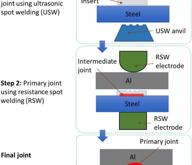
Recently research at the Ohio State University is developing methods that combine the benefits of ultrasonic welding and resistance spot welding. Y. Lu and co-workersL-10 developed the ultrasonic plus resistance spot welding process (U+RSW). In this process thin aluminium sheet was joined with steel sheet via ultrasonic welding, followed by RSW between the aluminium side of previously sheet and aluminium sheet as shown in Figure 1. In this study they used 1-mm-thick AA6061-T6 to 0.9-mm-thick AISI 1008 steel with 0.4-mm-thick AA6061-T6 as the insert.

Figure 1: Schematic diagram of U + RSW process. VD is the sonotrode’s vibration direction for USW of intermediate joint.L-10
The U+RSW method showed improved mechanical properties (Figure 2), tensile shear strength and energy absorbed prior to failure. It has shown a relatively thin intermetallic layer.

Figure 2: Effect of welding current on tensile shear strength and fracture energy of welded dissimilar joints of AA6061 to AISI 1008 steel. The welding time and the electrode force for RSW were kept constant at 0.083 s and 3.56 kN, respectively.L-10
Another research group have developed ultrasonic resistance welding process (URW), that apply in situ ultrasonic waves during the resistance spot welding process.S-17 The schematics of the process is shown in the Figure 3. Al-6061T6 and electrogalvanized TRIP 780 with dimensions of 70Lx 25Wx 1.6T mm3 and 70Lx 25Wx 1.3T mm3 respectively were used in this study.

Figure 3: URW Setup (a) Schematic illustration; (b) Flowchart of the URW process.S-17
The URW process have shown improved mechanical properties and defect free interface compared to the RSW process. In situ ultrasonic vibration facilitated the breakdown of the surface oxide and contaminants, which modifies contact resistance and heat generation rate accordingly. If melting occurs, ultrasonic vibration promoted wetting of the molten aluminium over the steel interface and resulted in the formation of defect-free, fully bonded interface as shown in Figure 4. Figure 5 compares the mechanical properties between the RSW & URW process. Comparing URW with traditional RSW, up to 300% increase in strength and more than 150% increase in displacement to failure is reported. SEM images of the fractured surface revealed that ultrasonic waves eliminated the eggcrate morphology generally observed in the RSW welds fractured surface, which is a typical representative of solidification cracking.

Figure 4: EDS line Scan of Al-6061 & TRIP 780 across interface for RSW at 11.4 kA (a-b) & at 13.4 kA (e-f) and for URW at 11.4 kA (c-d) & at 13.4 kA (g-h).S-17

Figure 5: Tensile test results (a) Joint shear strength from 11.4 kA (30 cycles) & 13.4 kA (20 cycles); (b) Energy absorption calculated via area under load-displacement curve for 11.4 kA (30 cycles) & 13.4 kA (20 cycles); (c-d) load-displacement curve for 11.4.S-17
Citations
Citation:
S-17. U. Shah and X. Liu, “Effects of ultrasonic vibration on resistance spot welding of transformation induced plasticity steel 780 to aluminum alloy AA6061,” Mater. Des., Vol. 182, p. 108053, Nov. 2019, doi.org/10.1016/j.matdes.2019.108053.


