Weld Quality with Modular Weld Head
This article summarizes a paper entitled, “Weld Quality Study of Projection Nut Welding with Modular Weld Head”, by F. Jiao, et al.F-7
The study investigates the weld quality of projection nut welding with a patent pending “quick release” modular weld head.
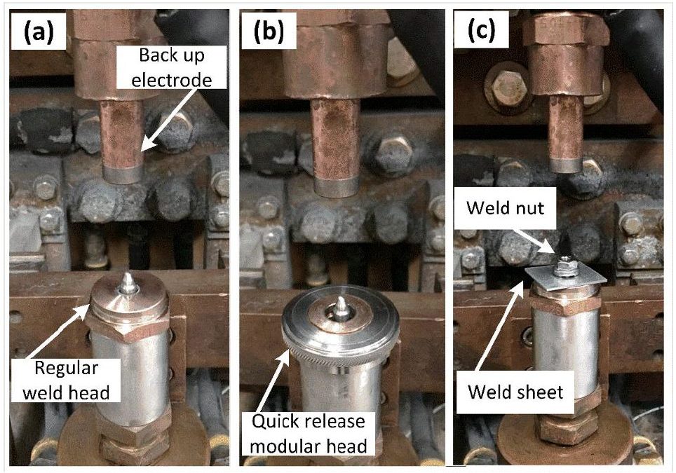
The weld nuts used in the study were 3 projection hex-flanged M6 weld nuts. Operating weld currents ranged from 26-32 kA. The welding time was 5 cycles and the applied electrode force was 450 lb. Figure 1 shows the set up for each test. Figure 2 shows the disassembled parts of the quick release modular weld head. Table 1 lists the material properties of the weld faces.
![Figure 1: Projection Nut Welding Set-Up [(a) with regular weld head, (b) with quick-release modular head, and (c) welding parts set up].](http://ahssinsights.org/wp-content/uploads/2020/07/3122_fig1.jpg)
Figure 1: Projection Nut Welding Set-Up [(a) with regular weld head, (b) with quick-release modular head, and (c) welding parts set up].F-7

Figure 2: Disassembled Parts of Patent-Pending Quick-Release Modular Weld Head.F-7
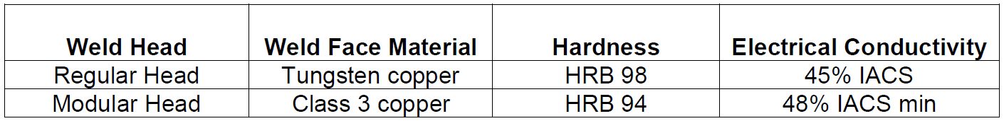
Table 1: Material Properties of Weld Faces.F-7
Figure 3 shows the cross section images of the projection welds. Both welds made a weld with 100-micron penetration. The weld made with the regular head had a slightly deeper HAZ as indicated by the dashed line. Figure 4 shows the microhardness profile of both projection welds. Generally, the hardness profile of the welds is quite similar.
![Figure 3: Optical Microscope Images of the Projection Welds After Etching [(a) with regular head (b) with modular head].](http://ahssinsights.org/wp-content/uploads/2020/07/3122_fig3.jpg)
Figure 3: Optical Microscope Images of the Projection Welds After Etching [(a) with regular head (b) with modular head].F-7

Figure 4: Microhardness of the Projection-Welded Sample with Different Weld Heads.F-7
Figure 5 shows the results of tensile testing on both projection welds. The fracture load with the modular head is higher than that with the regular head at 26 kA. At other currents, the fracture load is very similar.
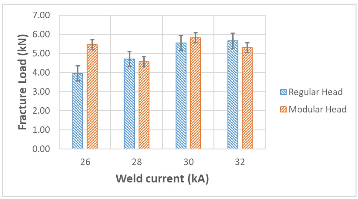
Figure 5: Variation of Fracture Load with Weld Current for Different Weld Head.F-7
Figure 6 shows the weld thickness difference between the modular head and the regular head. The results indicate the weld performance of both heads is very similar up to 1000 welds.
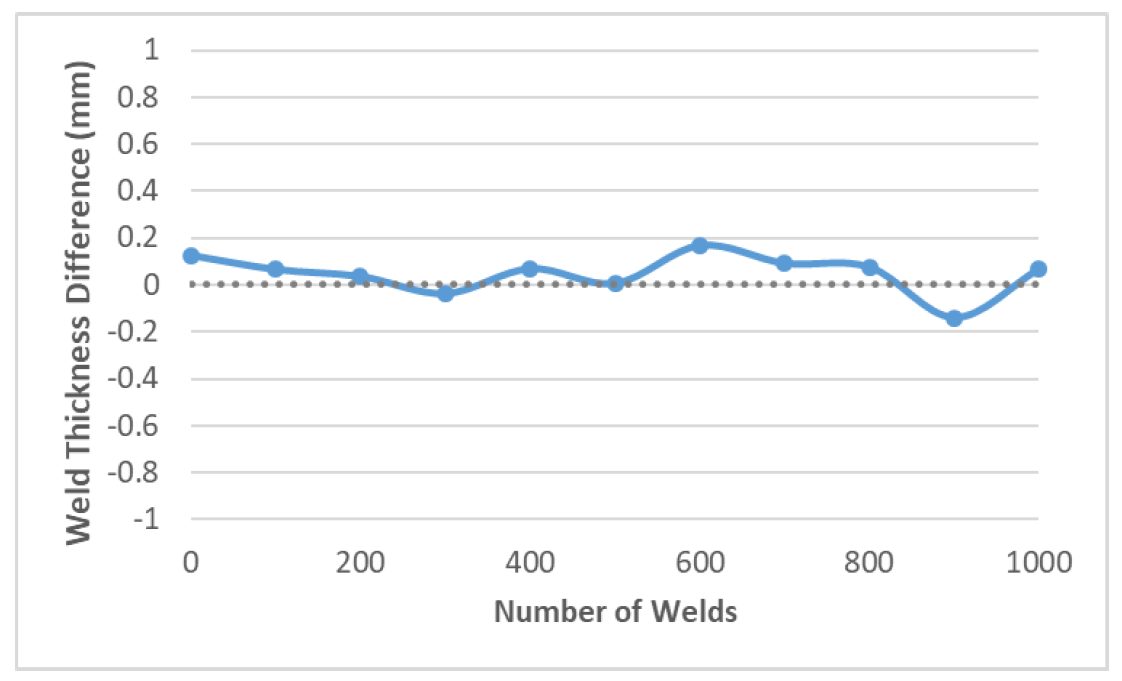
Figure 6: Variation of Weld Thickness Difference Between Regular Head and Modular Head.F-7