FSSW Method for Joining Ultra-Thin Steel Sheet
This article summarizes a paper entitled, “An Evaluation of Friction Stir Spot Welding as a Method for Joining Ultra-thin Steel Sheet,” by Y. Hovansk, et al.H-10
The study analyzes Friction Stir Spot Welding (FSSW) as a process for assembly of two sheet stack ups. The steel sheet used for this study is CR4-GI, a hot dip galvanized ultra-low carbon interstitial free steel with a tensile strength of 280 MPa. Thicknesses of both 0.45 and 1.2 mm were used to create dissimilar thickness, two-sheet stack-ups. Preparation for joining via FSSW did not alter the zinc coating. FSSW joints were evaluated in lap shear tensile, T-peel, and cross tension.
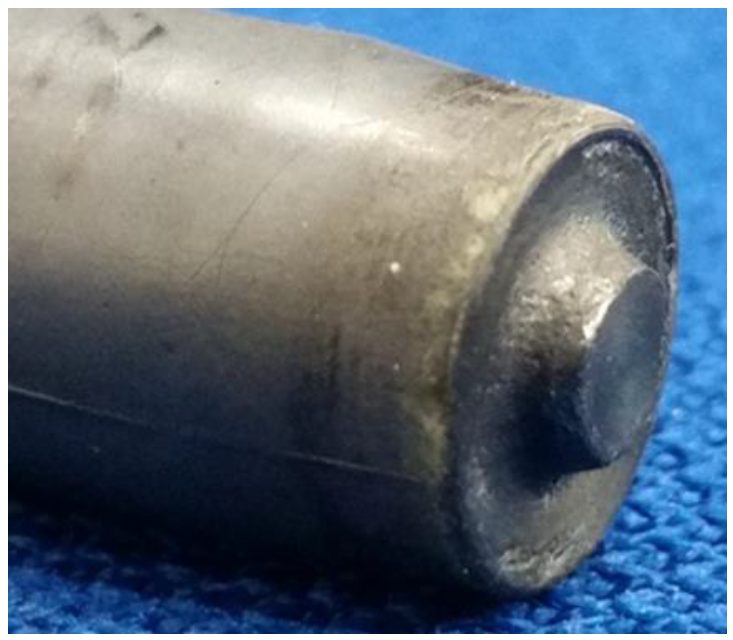
FSSW welds were welded with an EKasin injection molded, silicon nitride tool shown in Figure 1. All welds were performed at 1600 rpm.
Figure 1: Representative Picture of a Silicon-Nitride FSSW Tool with a 10-mm-diameter Shoulder and a 1.15-mm Probe Length.H-10
The zinc coating that originally covered the sheet surface was extruded beneath the FSSW tool to the outer edges of the weld as seen in Figure 2. Figure 3 shows a representative weld on a T-peel specimen.
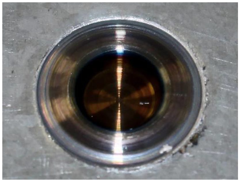
Figure 2: Optical Image of the Top Surface of a Friction Stir Spot Weld in CR4-GI.H-10
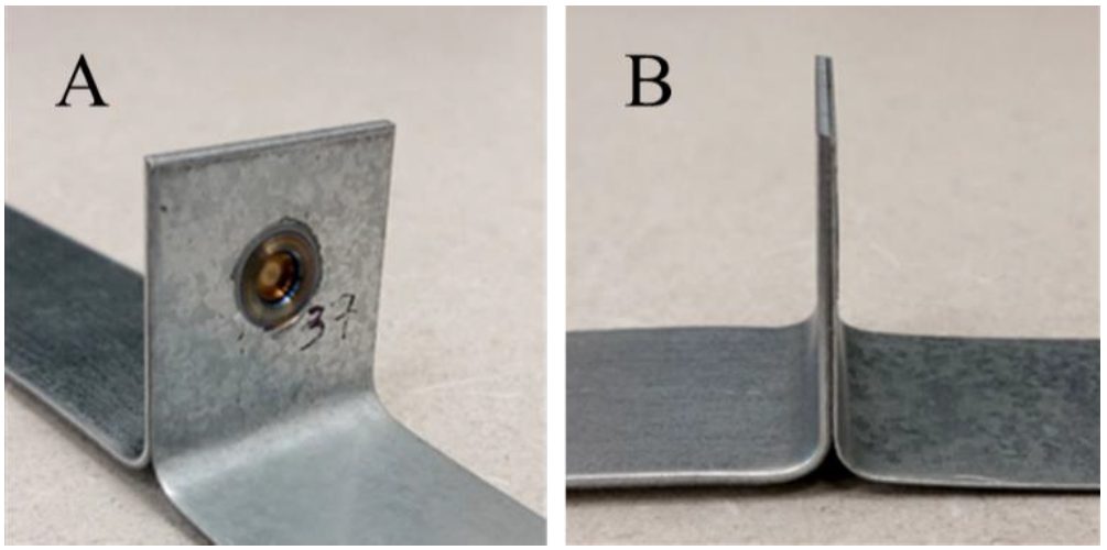
Figure 3: A T-Peel Specimen Produced on a 25-mm-wide Strips with FSSW 0.45- to 1.2-mm-thick CR4-GI.H-10
A minimum of 25 specimens were produced for each geometry tested, however, these specimens were performed at various times throughout weld development and data is shown below. Figure 4 shows the load-extension curves for a set of nine friction stir spot welds. Figure 5 shows a representative fracture of lap-shear tensile specimen.
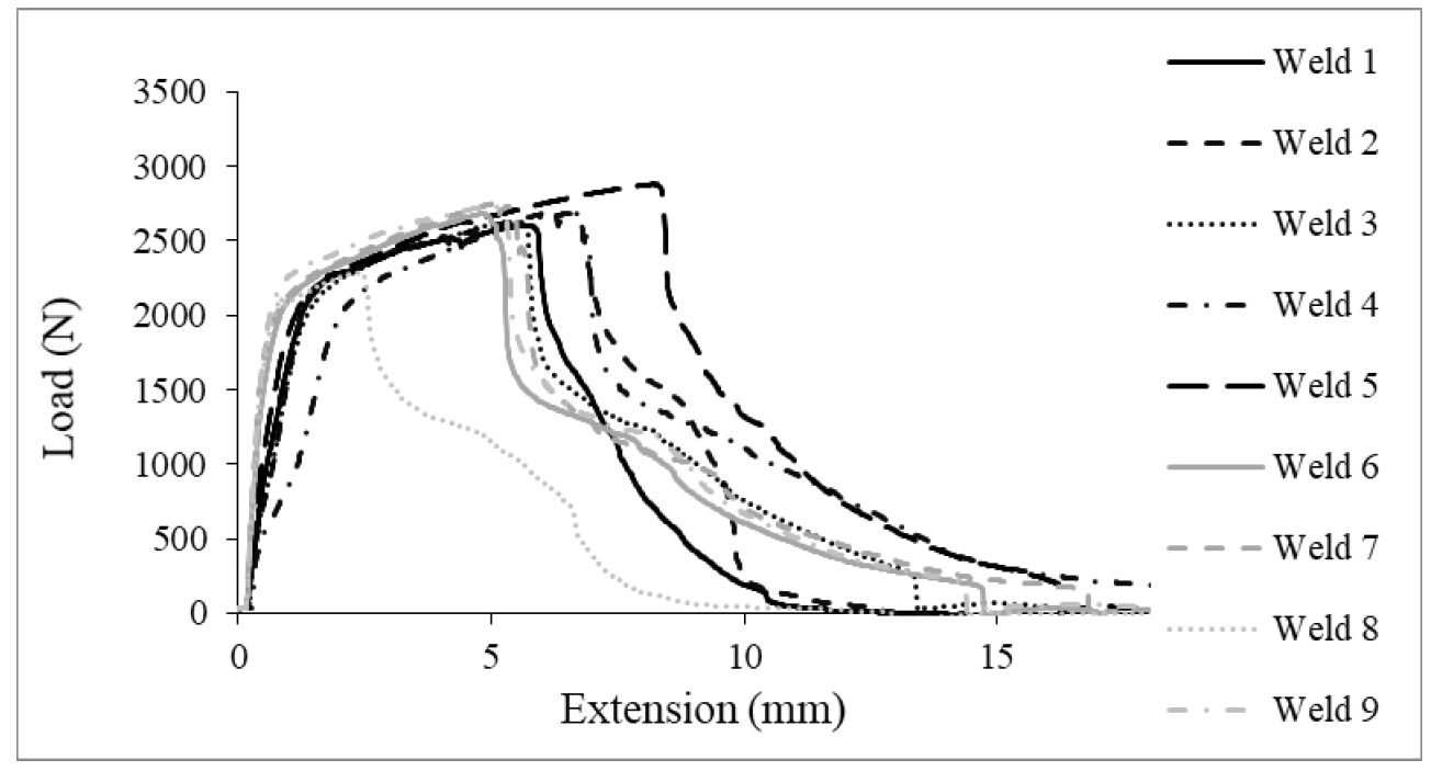
Figure 4: Test Results for Lap-Shear Tensile Data of Friction Stir Spot Welds in 0.45-mm CR4-GI.H-10
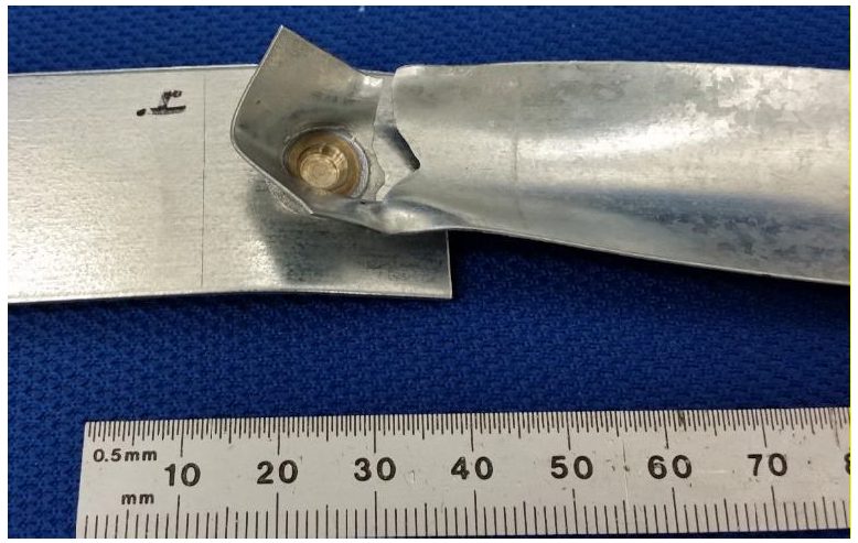
Figure 5: Friction Stir Spot Weld in 0.45-mm CR4-GI Fractured in Lap-Shear Tensile.H-10
Figure 6 shows the load-extension curves for a set of eight friction stir spot welds tests in T-peel. A representative fracture of T-peel specimen is shown in Figure 7.
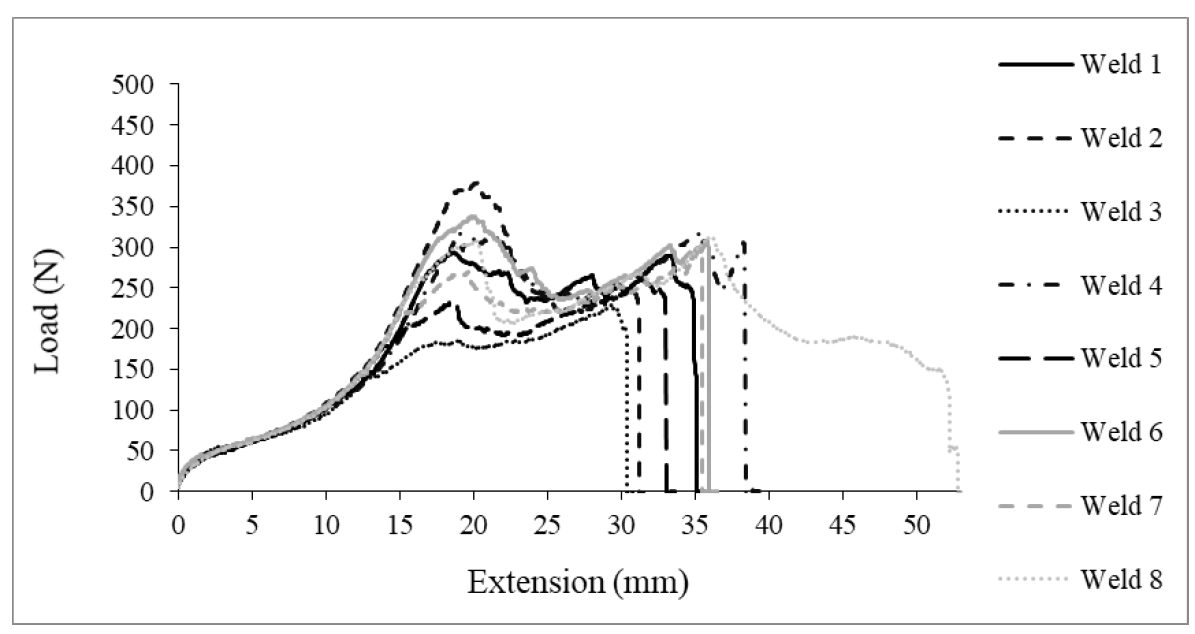
Figure 6: Test Results for T-Peel Data of Friction Stir Spot Welds in 0.45-mm CR4-GI.H-10
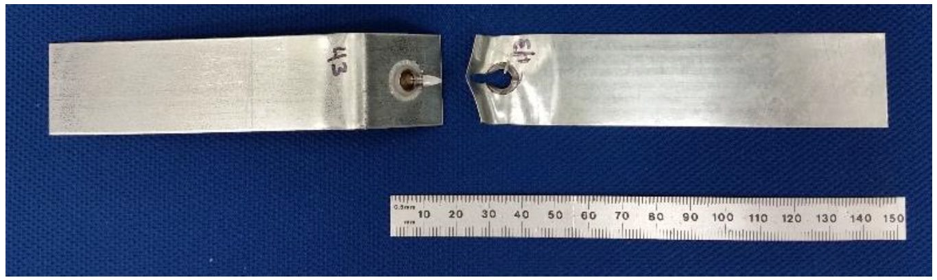
Figure 7: Friction Stir Spot Weld in 0.45-mm CR4-GI Fractured in T-Peel.H-10
Figure 8 shows the load extension curves for a set of 13 friction stir spot welds tested in cross tension. Representative geometry and fracture of cross tension specimen are shown in Figure 9.
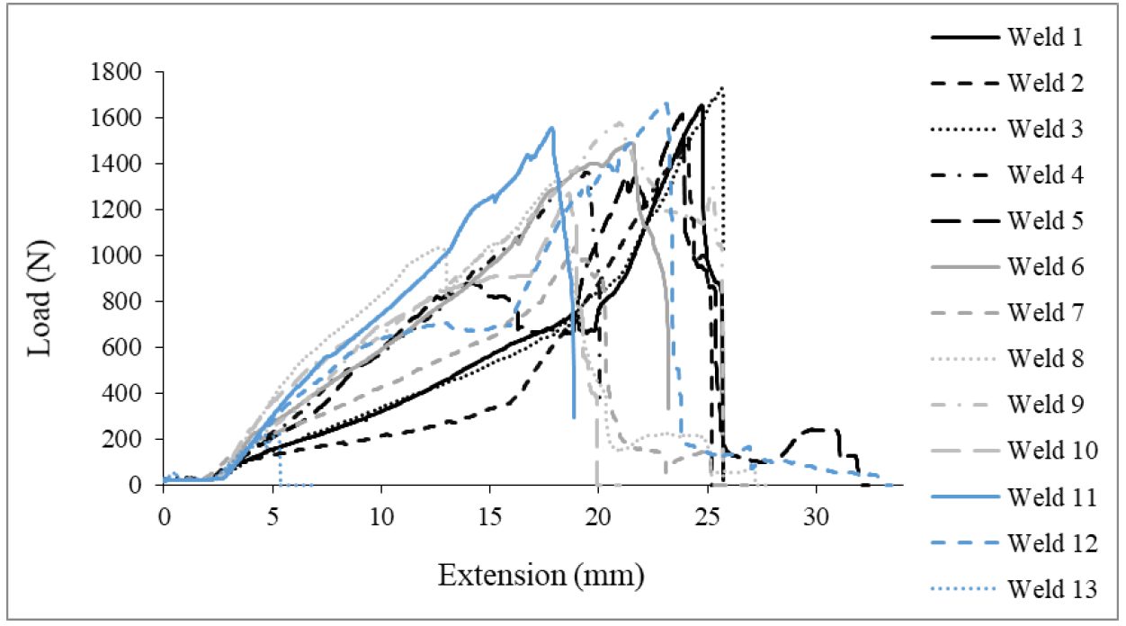
Figure 8: Test Results for Cross-Tension Data of Friction Stir Spot Welds in 0.45-mm CR4-GI.H-10
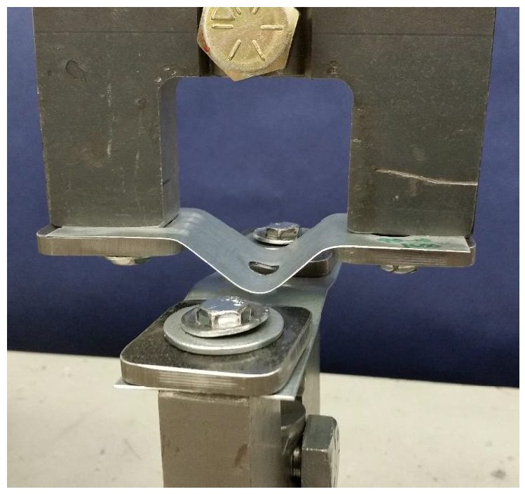
Figure 9: Friction Stir Spot Weld in 0.45-mm CR4-GI Fractured in Cross-Tension.H-10
A table showing the overall results for the FSSW joints produced herein are shown in Table 1 below:
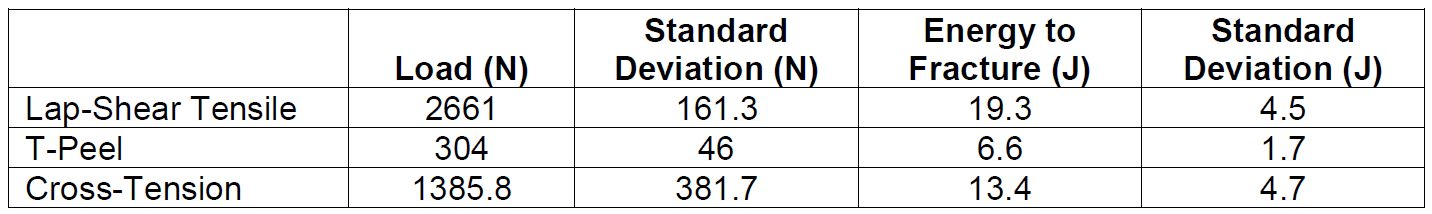
Table 1: Summary of Fracture Loads and Energies from Friction Stir Spot Welds made in Ultra-Thin CR4-GI for Three Unique Test Configurations.H-10
While each specific test orientation demonstrated the ability for the weld nugget to pull out of the ultra-thin top sheet and remain with the lower 1.2-mm-thick sheet, the overall ratios between fracture loads suggest there is an area for improvement with respect to T-peel.