Arc Welding
Gas Metal Arc Welding: Introduction
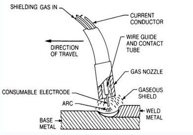
Gas Metal Arc Welding (GMAW) (Figure 1), commonly referred to by its slang name “MIG” (metal inert gas welding) uses a continuously fed bare wire electrode through a nozzle that delivers a proper flow of shielding gas to protect the molten and hot metal as it cools. Because the wire is fed automatically by a wire feed system, GMAW is one of the arc welding processes considered to be semi-automatic. The wire feeder pushes the electrode through the welding torch where it makes electrical contact with the contact tube, which delivers the electrical power from the power supply and through the cable to the electrode. The process requires much less welding skill than Shielded Metal Arc Welding (SMAW) or Gas Tungsten Arc Welding (GTAW) [LINK TO SECTION] and produces higher deposition rates.
Figure 1: GMAW
The basic equipment components are the welding gun and cable assembly, electrode feed unit, power supply, and source of shielding gas. This set up includes a water-cooling system for the welding gun which is typically necessary when welding with high duty cycles and high current.
GMAW became commercially available in the late 1940s offering a significant improvement in deposition rates and making welding more efficient. Deposition rates are much higher than for SMAW and GTAW, and the process is readily adaptable to robotic applications. Because of the fast welding speeds and ability to adapt to automation, it is widely used by automotive and heavy equipment manufacturers, as well as a wide variety of construction and structural welding, pipe and pressure vessel welding, and cladding applications. It is extremely flexible and can be used to weld virtually all metals. Relative to SMAW, GMAW equipment is a bit more expensive due to the additional wire feed mechanism, more complex torch, and the need for shielding gas, but overall it is still relatively inexpensive.
GMAW is “self-regulating”, which refers to the ability of the machine to maintain a constant arc length at all times. This is usually achieved using a constant-voltage power supply, although some modern machines are now capable of achieving self-regulation in other ways. This self-regulation feature results in a process that is ideal for mechanized and robotic applications.
Figure 2 provides important GMAW terminology. Of particular importance is electrode extension. As shown, electrode extension refers to the length of filler wire between the arc and the end of the contact tip. The reason for the importance of electrode extension is that the longer the electrode extension, the greater the amount of resistive (known as I2R) heating that will occur in the wire. Resistive heating occurs because the steel wire is not a good conductor of electricity. This effect can become significant at high currents and/or long extensions, and can result in more of the energy from the power supply being consumed in the heating and melting of the wire, and less in generating arc heating. As a result, significant resistive heating can result in a wider weld profile with less penetration or depth of fusion. The stand-off distance is also an important consideration. Distances that are excessive will adversely affect the ability of the shielding gas to protect the weld. Distances that are too close may result in excessive spatter build-up on the nozzle and contact tip. Various gases are being used for shielding the in GMAW process. The most common ones include argon (Ar), helium (He), and carbon dioxide (CO2) and combinations of these. Figure 3 illustrates the effect of the shielding gas on the weld profile.
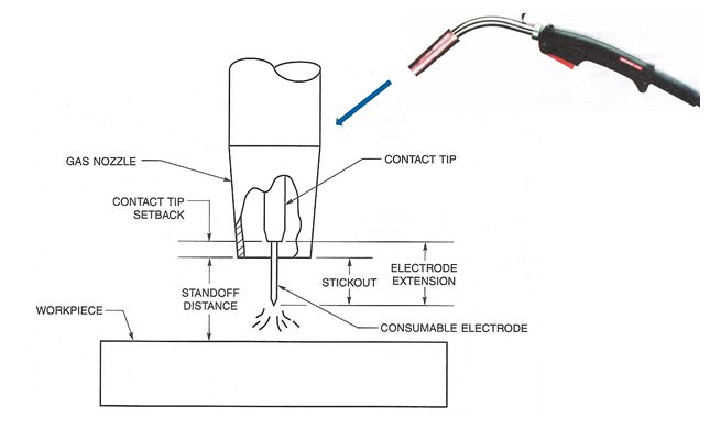
Figure 2: Common GMAW terminology
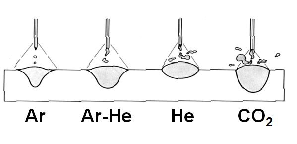
Figure 3: Effect of shielding gas on weld profile
AWS A5.18 is the carbon steel filler metal specification for SMAW, and includes both filler metal for both GMAW and GTAW. A typical electrode is shown on Figure 4. The “E” refers to electrode and the “R” refers to rod which means the filler metal can be used either as a GMAW electrode which carries the current, or as a separate filler metal in the form of a rod that could be used for the GTAW process. The “S” distinguishes this filler metal as solid (vs. the “T” designation which refers to a tubular GCAW electrode or “C” for composite electrode), the number, letter, or number/letter combination which follows the S refers to a variety of information about the filler metal such as composition, recommended shielding gas, and/or polarity.
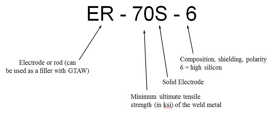
Figure 4: Typical AWS A5.18 electrode.
In summary, the GMAW process offers the following advantages and limitations:
- Advantages:
- Higher deposition rates than SMAW and GTAW
- Better production efficiency vs. SMAW and GTAW since the electrode or filler wire does need to be continuously replaced
- Since no flux is used there is minimal post-weld cleaning required and no possibility for a slag inclusion
- Requires less welder skill than manual processes
- Easily automated
- Can weld most commercial alloys
- Deep penetration with spray transfer mode
- Depending on the metal transfer mode, all position welding is possible
- Limitations:
- Equipment is more expensive and less portable than SMAW equipment
- Torch is heavy and bulky so joint access might be a problem
- Various metal transfer modes add complexity and limitations
- Susceptible to drafty conditions
GMAW Procedures and Properties
Despite the increase alloying content used for Q&P 980, there is no increased welding defect type or rate compared with mild steel Gas Metal Arc Welding (GMAW) welds. Figure 5 is the microhardness profile of 1.6-mm Q&P 980’s GMAW weld joint. Both welded seam and HAZ are all less than 500 HV, and there is no obvious softened zone in HAZ.B-4
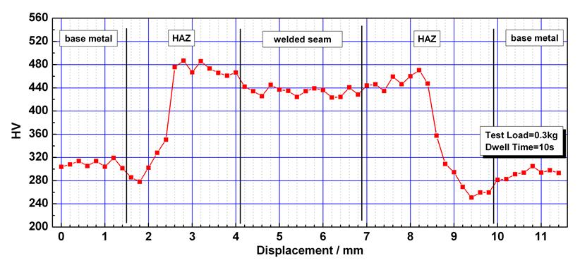
Figure 5: Microhardness profile of 1.6-mm DP 980’s GMAW weld joint. B-4
GMAW was used on three steels studied under a range of conditions. The left represents the FZ location and the middle is the HAZ. The figures show various degrees of HAZ hardening and softening depending on material grade and other conditions. The highest hardness occurs in the near HAZ, while the softest point is in the far HAZ. DP 980 [LINK TO THE MATERIAL IN METALLURGY] shows the greatest degree of HAZ hardening and softening. The nominally high CR condition is a combination of low heat input and heat sink. The plots show that CR tends to have the largest effect on the DP steels, with the TRIP steel being somewhat less affected. Pre-strain has the largest effect on the TRIP Base Metal (BM) , increasing the BM hardness by about 25%. The hardness of the softest location of the TRIP 780 HAZ is also increased by pre-strain, although degree of softening (about 20%) is not significantly changed. Pre-straining increased the DP 780 BM hardness by only about 10%. Pre-straining did not affect the peak HAZ hardness for either material. Post-baking did not appear to have a significant influence on the HAZ hardness profiles of the DP 780 material or the TRIP 780 material, regardless of pre-strain condition (Figures 6 through 8).
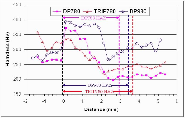
Figure 6: Hardness profiles of DP 780, TRIP 780, and DP 980 lap welds produced with the nominally high CR, no pre-strain or post-baking.P-7
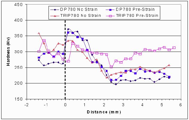
Figure 7: Hardness profiles of DP 780 and TRIP 780 welds
produced both with and without pre-strain for the high CR condition.E-1
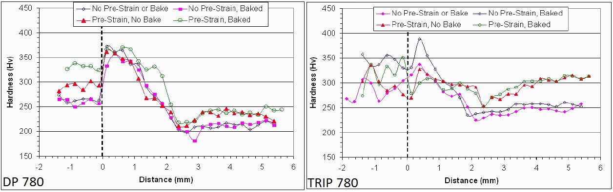
Figure 8: Hardness profiles of DP 780 and TRIP 780 welds produced both
with and without post-baking for both pre-strained sheet and not pre-strained
sheet for the nominally high CR condition.E-1
TRIP 780 lap joint static tensile results for different filler metal and CR conditions are shown in Figure 9. The results are expressed in terms of joint efficiency and the strain at peak load. The data indicates joint efficiencies ranged from about 50% to about 98%. Strains at peak load ranged from less than 3% to nearly 8%. Fracture occurred either in the far HAZ or at the weld fusion boundary. Filler metal strength had no discernable effect on the tensile properties. Figure 9 shows static tensile test results of the TRIP 780 butt joints. All the welds failed in the softened region of the far HAZ with joint efficiencies in excess of 89%. On average, welds made using higher CR experienced higher strains during loading than those made using lower CR. As was the case with the lap welds, filler metal strength did not appear to influence the static tensile properties. The abbreviations of high and low “CR” indicate high and low CR used for each weld.
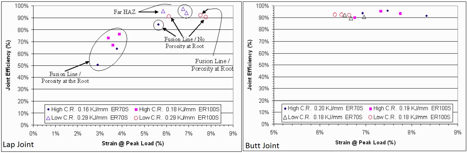
Figure 9: Static tensile test results of TRIP 780 lap and butt joints.E-1
The static tensile test results of the DP 780 butt welds are shown in Figure 10. All welds failed in the softened region of the far HAZ. As shown, the high CR welds had joint efficiencies in excess of 90%. The high CR welds also appear to have slightly greater strains at peak load.
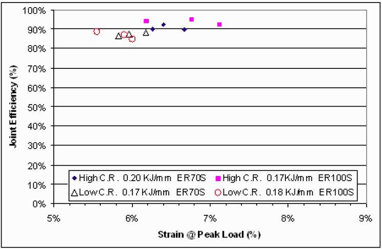
Figure 10: Static tensile test results of DP 780 butt joints.E-1
Figure 11 (left) shows the TRIP 780 lap joint dynamic tensile results for different filler metal and CR conditions. UTS ranged from 372 to 867 MPa (54 to 126 ksi) and strain at peak load ranged from less than 1% to over 5%. The high CR lap joints had lower strengths and strains at peak load. These welds failed along the fusion line presumably due to porosity present at the root. All the low CR lap welds produced with the ER70S-6 wire failed in far HAZ of the bottom sheet. Of the low CR lap joints produced with the ER100S-G wire, two dynamic tensile specimens failed in the softened region of the far HAZ, and one failed along the fusion line of the top sheet without the presence of porosity at the weld root. Analysis of Figure 11 (left) indicates that filler metal strength did not have a distinguishable effect on the dynamic tensile test results. Figure 11 (right) shows the dynamic tensile test results of the TRIP 780 butt joints. All failed in the softened region of the far HAZ. The UTS of the butt joints ranged from 840 to 896 MPa (122 to 130 ksi), and strain at peak load was generally between 3 and 4%. The figure indicates that neither filler metal strength nor CR condition had a distinguishable effect on the dynamic tensile test results of the butt joints.
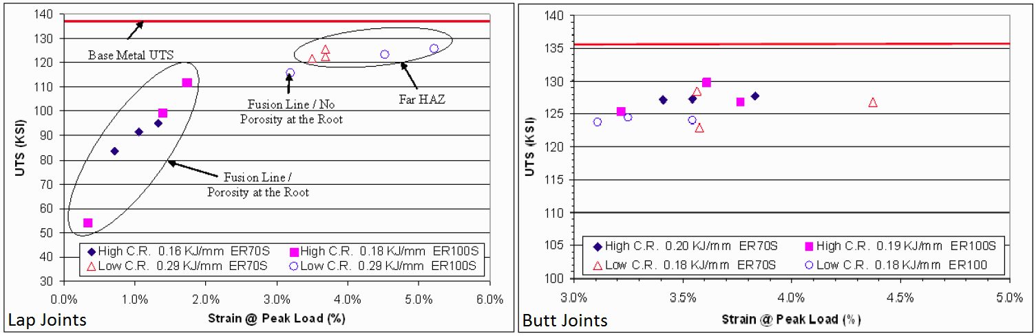
Figure 11: Dynamic tensile test results of TRIP 780 lap joints and butt joints.E-1
The dynamic tensile test results of the DP 780 butt joints are shown in Figure 12. All failed in the softened region of the far HAZ. UTS ranged from 841 to 910 MPa (122 to 132 ksi), and strain at peak load ranged from 2.25% to less than 4.0%. It should be noted that similar UTS were obtained for the DP 780 and TRIP 780 butt joints. On average, TRIP 780 butt joints had slightly higher strain at peak load. Neither filler metal strength nor CR condition appears to have a distinguishable effect on the dynamic tensile properties.
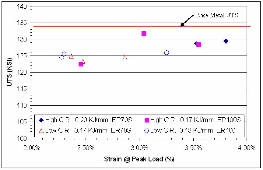
Figure 12: Dynamic tensile test results of DP 780 butt joints.E-1
Back To Top
Arc Welding
Fundamentals and Principles of Arc Welding
This section serves as an introduction to all the arc welding processes. The common features and important concepts and terminology of this family of processes are reviewed, with more process-specific details provided in the sections covering the specific processes.
Arc welding refers to a family of processes that rely on the extreme heat of an electric arc to produce a weld. They may or may not rely on additional filler metal to create the weld. Although generally considered “low-tech”, arc welding continues to be very popular primarily due to its low equipment cost and high flexibility. Some of the key discoveries that led to modern arc welding include the discovery of the electric arc in the 1820s (Davies), the first welding patent using a carbon electrode in 1886, and the first covered electrode in 1900 (Kjellberg).
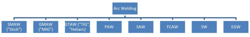
The most common arc welding processes today are illustrated in Figure 1. The abbreviations refer to American Welding Society (AWS)A-11 terminology as follows:
- EGW – Electroglas Welding
- FCAW – Flux-Cored Arc Welding
- GMAW – Gas Metal Arc Welding
- GTAW – Gas Tungsten Arc Welding
- PAW – Plasma Arc Welding
- SAW – Submerged Arc Welding
- SMAW – Shielded Metal Arc Welding
- SW – Arc Stud Welding
Figure 1: Common arc welding processes.
Whereas the welding engineer should always use proper AWS terminology during formal communications, in reality, the use of slang terminology for SMAW, GMAW, and GTAW processes is very common. Thus, where appropriate the “slang” terminology is included in italics.
With all arc welding processes, the initiation of an arc basically completes (or closes) an electrical circuit consisting of the ground and work cables, the welding torch, the workpiece or parts to be welded, and the secondary of the welding power supply. Voltages provided by the power supply are commonly either 60 or 80 V. Such voltages are high enough to establish and maintain an arc, but low enough to minimize the risk of electric shock. Once the arc is struck, actual arc voltages commonly range between 10 and 35 V. Direct Current (DC) is most common, but Alternating Current (AC) is sometimes used. Pulsed DC is becoming a common feature in modern welding power supplies. The electrical polarity used during arc welding is very important, but it has different effects with different processes. The effect of polarity on heat input is especially important with GTAW and GMAW, but the effects are opposite. With GTAW, direct-current electrode negative (DCEN) produces the greatest amount of heat into the part and is the most common polarity. However, with GMAW, direct-current electrode positive (DCEP) produces the greatest amount of heat into the part and is used almost exclusively with this process (Figure 2).
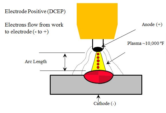
Figure 2: DCEP – common with GMAW.
The heat input during arc welding is primarily a function of weld travel speed and current, based on the following equation:

Although voltage appears to play a prominent role in the heat input equation, it is a parameter that is chosen primarily to create the most stable arc, not to affect heat input.
AWS filler metal classifications vary somewhat depending on the process. A common example is the classification system for SMAW electrodes, “EXXXX” where “E” stands for electrode, the two digits following the E give the minimum deposited weld metal tensile strength in kips per square inch (ksi) (there will be a third digit if the strength is 100 ksi or higher), the third “X” provides information on what welding positions that electrode can be used for, and the final “X” provides information about the coating type. The electrode and filler metal classification schemes will be covered in more detail in the subsequent chapters covering each of the arc welding processes.
Shielding
When metals are heated to high temperatures approaching or exceeding their melting point, diffusion rates are accelerated and the metals become very susceptible to contamination from the atmosphere. Elements that can be most damaging are oxygen, nitrogen, and hydrogen, and contamination from these elements can result in the formation of embrittling phases (such as oxides and nitrides), and porosity. To avoid this contamination, the metal must be shielded as it solidifies and begins to cool. The arc welding processes all rely on either a gas or a flux, or a combination of both for shielding. The way these processes are shielded is their main distinguishing feature from one another.
Processes such as GMAW, GTAW, and PAW rely solely on gas shielding. Shielding gasses protect by purging the susceptible metal from atmospheric gasses. The GMAW process commonly uses argon (Ar), carbon dioxide (CO2), or blends of Ar and CO2. CO2 gas produces more spatter and a rougher weld appearance. It can produce fast welding speeds, is readily available, and is cheap. Additions of CO2 or small amounts of O2 to Ar can improve puddle flow. The choice of shielding gas for GMAW plays a major role in the type of molten metal transfer mode from the electrode to the weld puddle.
Arc Welding Weld Joints and Types
The selection of a proper weld joint and weld type is a very important aspect of arc welding. The joint refers to how the workpiece or parts that are being welded are arranged relative to each other, and weld type refers to how the weld is formed in the joint. Specifically in arc welding, there are numerous joint types, but only two weld types, a fillet and a groove weld. A fillet weld offers the advantage of requiring no special joint preparation because the geometry of the joint provides the appropriate features to place the weld. Groove welds facilitate the creation of full-penetration welds which are often required in critical applications. The choice of weld and joint type is often dictated by the design of the component being welded but will play a major role in the properties of that joint. The thickness of the parts being welded, as well as the material and type of welding process being used may also affect the choice of weld or joint type. Some very common arc welding joints and weld types are shown in Figure 3. Basic welding positions are shown in Figure 4. It is recommended that all welding joints be positioned for welding in either the flat or horizontal position whenever possible. The horizontal or vertical plane of the flat and horizontal joint may vary up to a maximum of 10 degrees.
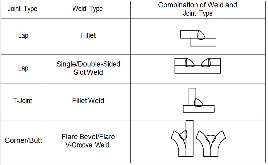
Figure 3: Typical arc welding joint and weld types for automotive sheet steel applications.
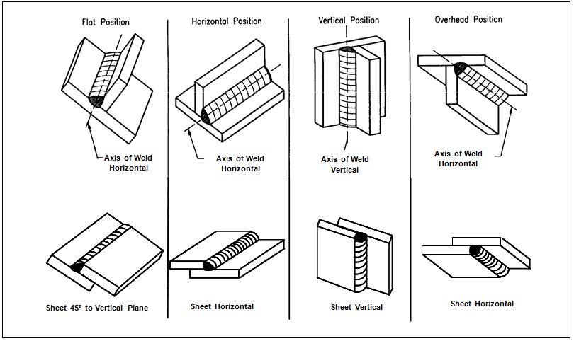
Figure 4: Basic arc welding positions.
Electrode Feed Rate
When using the semiautomatic arc welding processes such as GMAW electrode feed rate (or wire feed speed) determines both deposition rate and current. Higher feed rates increase weld metal deposition and increase current since melting rates at the end of the wire must increase as the wire feed speed increases. As a result, with the semiautomatic processes, current is typically adjusted by changing the wire feed speed since the two are relatively proportional. Typical wire feed speeds are between 100 and 500 inches per minute (ipm).
Welding Travel Speed
Travel speed refers to how fast the welding arc is moving relative to the workpiece. The heat input equation clearly shows that travel speed, like current, plays a direct role in the amount of heat into the part. Faster speeds produce less heat into the part and reduced weld metal deposit. The choice of travel speed is typically driven by productivity, with the obvious desire to usually weld as fast as possible. Travel speed is independent of current and voltage and may be controlled by the welder or mechanized. Typical travel speeds range between 5 and 100 ipm.
Arc Welding Safety
There are many hazards associated with arc welding that are not only important concerns for the welder, but for personnel working around any arc welding operations. This section will provide a very brief overview of the most common hazards of which the welding personnel should be aware. It is strongly recommended regarding safety in arc welding and other welding and associated processes to refer to the American National Standards Institute (ANSI) Document Z49.1, “Safety in Welding, Cutting, and Allied Processes”.
Ultraviolet radiation from the arc can damage the eyes and burn the skin in the same way skin is burned from the sun. This requires the use of proper shielding for the eyes and protective clothing to cover any exposed skin. Personnel working near arc welders should be careful not to glance at an open arc without proper shielding. Sparks and spatter during welding mandate the need for proper eye protection for anyone near the welding operation. Additional protective helmets are needed for the welder. Although the low voltages used in arc welding are relatively safe, proper electrical safety must be exercised at all times, including grounding of parts and equipment and avoiding damp conditions.
Welding fumes can be hazardous to the welder when inhaled over long periods of times so proper ventilation is paramount. Shielding gases can produce suffocation in enclosed spaces, such as when welding in tanks. Ar is heavier than air, and in the absence of proper ventilation, will displace oxygen when it fills a room. Helium is lighter than air producing a similar risk for overhead welding. Compressed shielding gas bottles can explode when mishandled or abused, or an arc strike can weaken the bottle, leading to an explosion. Hot metal is always a hazard with fusion welding processes like arc welding. When working around a welding operation, one should always assume that any piece of metal is hot. Welding arcs and associated hot metal spatter are ready sources for ignition of flammable materials in the vicinity of welding. Many fires have been started by careless welders who are not aware of any combustible material.A-11, P-6
Arc Welding Procedures
Conventional arc welding (for example GMAW, TIG, and plasma) can be used for AHSS in a similar way to mild steels. The same shielding gases can be used for both AHSS and mild steels. For automotive applications, a design gap tolerance (G) of 0-0.5 mm is allowed for all weld joints, as illustrated in Figure 5. An edge trim tolerance (Et) of ±0.5 mm is required where the edge is part of the weld joint, as shown in Figure 6. The variation in edge location causes variation in alignment of the electrode wire with the weld joint, as shown in Figure 6. Misalignment of the electrode may cause poor weld shape, improper fusion and burn-though. To control this variable, the trim tolerance at the weld joint must be held to ±0.5 mm and the electrode must maintain a root joint alignment tolerance of ±0.5 mm.
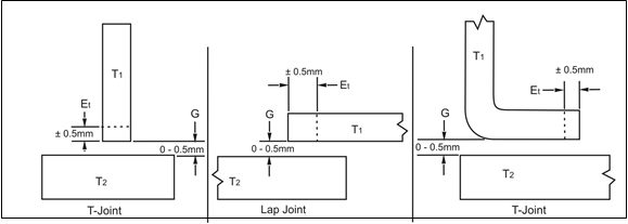
Figure 5: Joint design tolerance.A-12
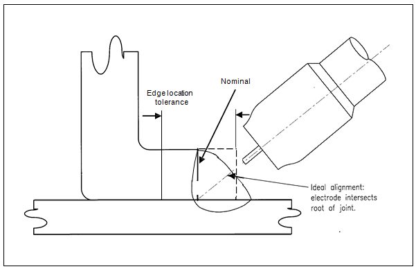
Figure 6: Edge location tolerance for fillet weld in a lap joint.A-12
A tolerance stack-up review must be performed on all GMAW joints. The worst-case maximum designed gap including tolerance stack-up shall not exceed what is listed in Figure 7. It is preferable to target the smallest possible gap (the thickness of the thinnest sheet or 1.5 mm, whichever is smaller). High-stress areas defined by CAE analysis and/or functional testing should be reviewed for weld optimization. Figure 8 illustrates techniques used to reduce the fillet weld stress concentration and to improve weld performance. These techniques include placing the weld start/stop away from corners and other high-stress areas, avoiding abrupt weld line direction changes when possible, etc.
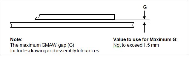
Figure 7: Maximum GMAW welding gap.A-12
Intermittent welds that are properly sequenced can help keep joints closed by reducing the heat input which reduces distortion. Meanwhile, intermittent welds also introduce weld starts and weld stops, both of which are stress risers. Similar to continuous welds, weld start/stops of intermittent welds should be placed away from high stress areas. Intermittent welds are specified by the center-to-center distance (i.e., pitch) and weld length, as shown in Figure 9.
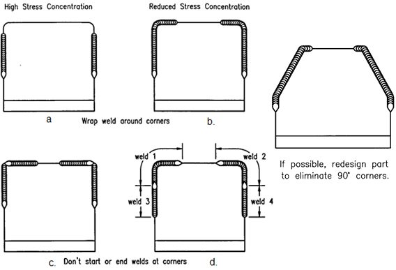
Figure 8: Reducing weld stress concentrations.A-12
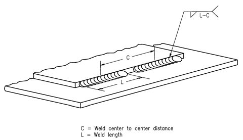
Figure 9: Intermittent fillet weld spacing.A-12
Despite the increased alloying content used for AHSS, there are no increased welding imperfections compared with mild steel arc welds. Changing from mild steel to AHSS may also result in a change of arc blow. The strength of the welds for AHSS increases with increasing base metal strength and sometimes with decreasing heat input. Depending on the chemical composition of AHSS [for example, mild Steels and DP steels with high martensite content and strength levels more than 800 MPa], the strength of the weld joint may be reduced in comparison to the base metal strength due to small soft zones in HAZ (Figure 10). For CP and TRIP grades, no soft zones occur in HAZ due to the higher alloying content for these steels in comparison to DP and mild steels.
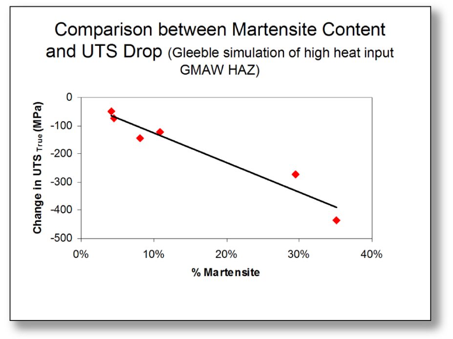
Figure 10: Relationship between martensite content and reduction in true ultimate tensile strength (UTS) (Data obtained by thermomechanical simulation of high heat input GMAW HAZ.D-1).
Higher strength filler wires are recommended for welding of AHSS grades with strength levels higher than 800 MPa (Figure 11 for single-sided welded lap joint and Figure 12 for butt joints). It should be noted that higher strength fillers are more expensive and, more importantly, less tolerant to the presence of any weld imperfections. When welding AHSS to lower strength or mild steel, it is recommended that filler wire with 70 ksi (482 MPa) strength be used. Single-sided welded lap joints are normally used in the automotive industry. Due to the asymmetrical loading and the extra bending moment associated with this type of joint, the strength of this lap joint is lower than that of the butt joint.
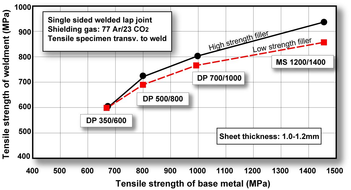
Figure 11: Influence of filler metal strength in arc welding of DP and mild steels. (Tensile strength is 560 MPa for low strength and 890 MPa for high-strength fillers. Fracture position in HAZ for all cases except DP 700/1000 and MS 1200/1400 combination with low-strength filler where fracture occurred in weld metal. Tensile strength equals peak load divided by cross-sectional area of sample.C-3)
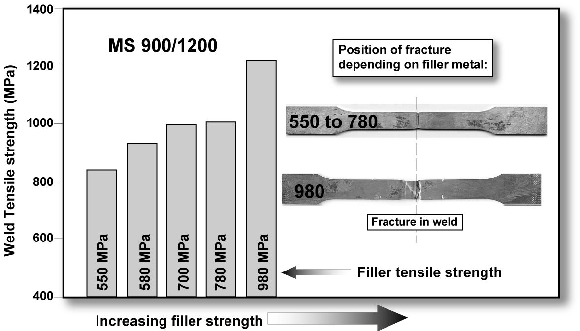
Figure 12: Influence of filler metal strength in GMAW (butt) welding on weld strength for MS steel. (Filler metal tensile strength range is 510-950 MPa.B-1)
Arc welds are normally used in local areas of vehicles where the loads are high. As required with all GMAW of any grade of steel, care should be taken to control heat input and the resulting weld metallurgy. The length of the GMA welds is often quite short. The reduction in strength for some of the AHSS GMA welds, in comparison to BM, can be compensated by increasing the length of the weld.
By adjusting the number and length (that is the total joined area) of welds, the fatigue strength of the joint can be improved. The fatigue strength of an arc-welded joint, in general, tends to be better than that of a spot-welded joint (Figure 13).
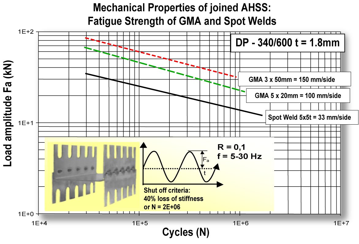
Figure 13: Fatigue strength of GMA-welded DP 340/600 compared to spot welding.L-2
Back To Top
