Arc Welding Procedures with AHSS
Arc welds are normally used for vehicle components where the loads are high, for example in shock towers and engine cradles. Conventional arc welding processes (GMAW, TIG, and plasma) can be used as effectively for AHSS as with mild steels. The same shielding gases can be used for both, and arc weld strength can often be equivalent to the base metal with shorter welds (although increasing the length of the weld usually achieves greater weld strength). By adjusting the number and length (that is the total joined area) of welds, the fatigue strength of the joint can be improved. Fatigue strength of arc welds is generally superior to spot welds.
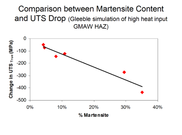
Figure 1: Martensite content compared to tensile strength.
Despite the increased alloying content used for AHSS, there are no increased arc welding imperfections compared with mild steel. The strength of the welds for AHSS increases with increasing base metal strength and sometimes with decreasing heat input. Depending on the chemical composition of AHSS [for example, mild Steels and DP steels with high martensite content and strength levels more than 800 MPa], the strength of the weld joint may be reduced in comparison to the base metal strength due to small soft zones in HAZ (Figure 1). For CP and TRIP grades, no soft zones occur in HAZ due to the higher alloying content for these steels in comparison to DP and mild steels.
Higher strength filler wires are recommended for welding of AHSS grades with strength levels higher than 800 MPa. It should be noted that higher strength fillers are more expensive and, more importantly, less tolerant to the presence of any weld imperfections. When welding AHSS to lower strength or mild steel, it is recommended that filler wire with 70 ksi (483 MPa) strength be used. Single-sided welded lap joints are normally used in the automotive industry, but due to the unsymmetrical loading and the extra bending moment associated with this type of joint, the strength of this lap joint is lower than that of the butt joint.
Gap Control
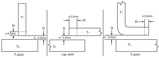
Figure 2: Joint design tolerance.
For automotive applications, a design gap tolerance (G) of 0-0.5 mm is allowed for all weld joints, as illustrated in Figure 2. An edge trim tolerance (Et) of ±0.5 mm is required where the edge is part of the weld joint, shown in this same figure.
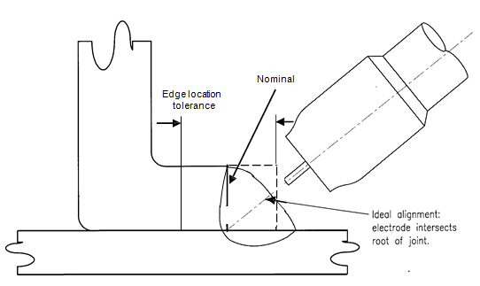
Figure 3: Edge location tolerance for fillet weld in a lap joint.
The variation in edge location causes variation in alignment of the electrode wire with the weld joint, as shown in Figure 3. Misalignment of the electrode may cause poor weld shape, improper fusion and burn-though. To control this variable, the trim tolerance at the weld joint must be held to ±0.5 mm and the electrode must maintain a root joint alignment tolerance of ±0.5 mm.
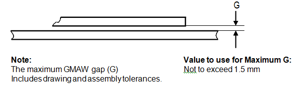
Figure 4: Maximum GMAW welding gap.
A tolerance stack-up review must be performed on all GMAW joints. The worst-case maximum designed gap including tolerance stack-up shall not exceed what is listed in Figure 4. It is preferable to target the smallest possible gap (the thickness of the thinnest sheet or 1.5 mm, whichever is smaller).
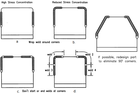
Figure 5: Reducing weld stress concentrations.
High-stress areas defined by CAE analysis and/or functional testing should be reviewed for weld optimization. Figure 5 illustrates techniques used to reduce the fillet weld stress concentration, which results in improved weld performance. These techniques include placing the weld start/stop away from corners and other high-stress areas, avoiding abrupt weld line direction changes when possible, etc.
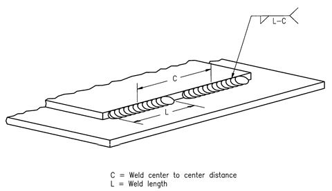
Figure 6: Intermittent fillet weld spacing.
Intermittent Welds – Intermittent welds can be employed as a method to reduce heat input and distortion (maintaining gap control), but they also introduce weld starts and weld stops, both of which are stress risers. Weld start/stops of intermittent welds should be placed away from high stress areas. Intermittent welds are specified by the center-to-center distance (i.e., pitch) and weld length, as shown in Figure 6.