Coatings
topofpage
- Hot Dip Galvanized and Galvannealed Coatings
- Electrogalvanized Coatings
- Zinc-Magnesium (ZM) Coatings
Many formed parts require corrosion protection, achieved through the application of some type of zinc-based or aluminum-based coating. The primary methods of applying zinc are through a hot dipped galvanizing line, or through an electro-galvanizing process. Aluminum-based coatings are applied in a hot dipped aluminizing line.
Both aluminized and galvanized coatings provide a barrier layer preventing corrosion of the underlying sheet steel. Zinc-based coatings also provide galvanic protection, where the zinc acts as a sacrificial anode if scratches or impact damage the coating, and therefore corrodes first before the underlying steel.
Aluminum melts at a higher temperature than zinc, which is why aluminized steels are more frequently used in applications requiring corrosion protection at elevated temperatures such as those found in the engine compartment and in the exhaust system. There are two types of aluminized coatings, known as Type 1 (aluminum with 9% silicon) and Type 2 (pure aluminum). The aluminum-silicon AlSi coating associated with press hardening steels are these Type 1 aluminized coatings. There are limited automotive applications for Type 2 pure aluminum coatings.
Zinc-magnesium coatings are relatively new options, offering enhanced cut edge corrosion protection, with lower friction and lower risk of galling and powdering than other common zinc coatings.
Most hot dipped galvanized lines produce surfaces which result in similar coefficients of friction for a given steel type. Different electrogalvanized coating lines may result in different surface morphologies, which can result in significantly different formability characteristics.
Passing a pure zinc-coated steel through a furnace allows the steel and zinc to inter-diffuse and results in an alloyed coating known as galvanneal. Hot dipped galvannealed coatings have improved joining due to the iron in the coating. Unlike the uniform coating composition associated with hot dip galvanized and electrogalvanized coatings, GA coatings are composed of different phases with varying composition. This may lead to different forming, joining, and painting characteristics when comparing products produced on different lines.
Differences in performance due to coating line characteristics is another reason why it is good practice to Identify the intended steel production source early in the die construction and die try-out process. Tryout material should come from the same source as will supply production.
Hot Dipped Galvanized and Galvannealed Coatings
The majority of sheet steel parts on a vehicle require corrosion protection, independent of whether they are made from mild or high strength steel and whether they are intended for exposed or unexposed applications. Hot dipped galvanizing – applying a zinc coating over the steel – is the most common way to achieve corrosion protection. It is an economical solution, since cold rolled steel can be annealed and coated in the same continuous operation.
A typical in-line continuous hot dip galvanizing line such as that shown in Figure 1 uses a full-hard cold rolled steel coil as the feedstock. Welding individual coils together produces a continuous strip. After cleaning, the strip is processed in a continuous annealing furnace where the microstructure is recrystallized, improving forming characteristics. Adjustments to the annealing temperature produces the desired microstructure associated with the ordered grade. Rather than cooling to room temperature, the in-process coil is cooled to just above 460 °C (860 °F), the temperature of the molten zinc bath it enters. The chemistry in the zinc pot is a function of whether a hot dipped galvanized or galvannealed coating is ordered. Hot rolled steels may be coated with the hot dip galvanizing process, but different processing conditions are used to achieve the targeted properties.
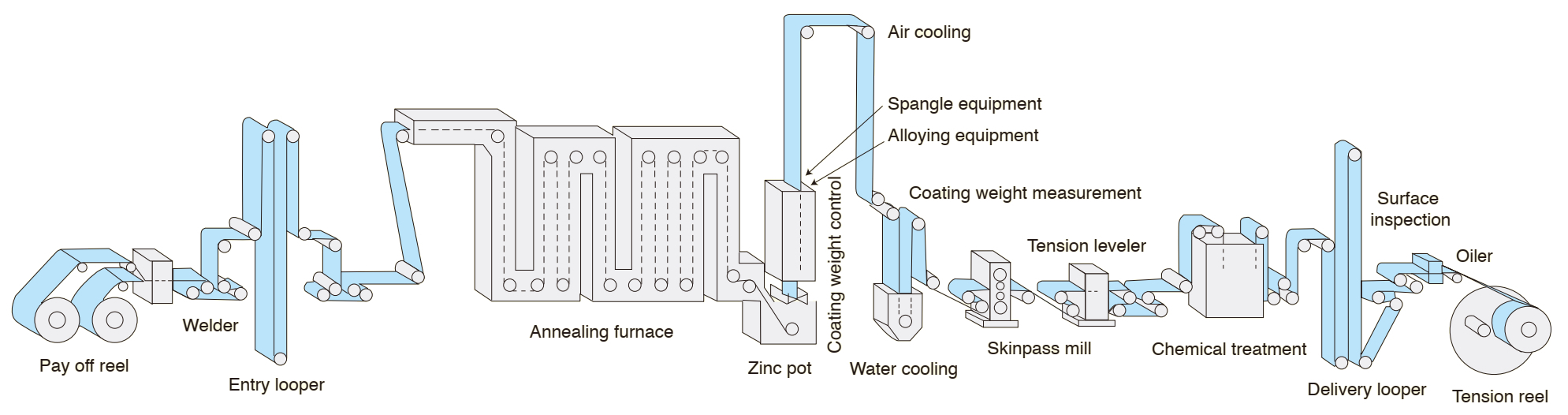
Figure 1: Schematic of a typical hot dipped galvanizing line with galvanneal capability.
There are several types of hot dipped coatings for automotive applications, with unique characteristics that affect their corrosion protection, lubricity for forming, weldability and paintability. One of the primary hot dipped galvanized coatings is a pure zinc coating (abbreviated as GI), sometime referred to as free zinc. The molten zinc bath has small amounts of aluminum which helps to form a thin Fe2Al5 layer at the zinc-steel interface. This thin barrier layer prevents zinc from diffusing into the base steel, which leaves the coating as essentially pure zinc.
Coils pass through the molten zinc at speeds up to 3 meters per second. Zinc coating weight is controlled by gas knives (typically air or nitrogen) blowing off excess liquid zinc as the coil emerges from the bath. Zinc remaining on the surface solidifies into crystals called spangle. Molten zinc chemistry and cooling practices used at the galvanizing line control spangle size. In one extreme, a large spangle zinc coating is characteristic of garbage cans and grain silos. In the other extreme, the zinc crystal structure is sufficiently fine that it is not visible to the unaided eye. Since spangle can show through on a painted surface, a minimum-spangle or no-spangle option is appropriate for surface-critical applications.
The other primary hot dipped coating used for corrosion protection is hot dipped galvanneal (abbreviated as GA). Applying this coating to a steel coil involves the same steps as creating a free zinc hot dipped coated steel, but after exiting the zinc pot, the steel strip passes through a galvannealing furnace where the zinc coating is reheated while still molten.
The molten zinc bath used to produce a GA coating has a lower aluminum content than what is used to produce a GI coating. Without aluminum to create the barrier layer, the zinc coating and the base steel inter-diffuse freely, creating an iron-zinc alloy with typical average iron content in the 8% to 12% range. The iron content improves weldability, which is a key attribute of the galvanneal coatings.
The iron content is unevenly distributed throughout the coating, ranging from 5% at the surface (where the sheet metal coating contacts the tool surface during forming) to as much as 25% iron content at the steel/coating interface. The amount of iron at the surface and distribution within the coating is a function of galvannealing parameters and practices – primarily the bath composition and time spent at the galvannealing temperature. Coating iron content impacts coating hardness, which affects the interaction with the sheet forming lubricant and tools, and results in changes in friction. The hard GA coatings have a greater powdering tendency during contact with tooling surfaces, especially during movement through draw beads. Powdering is minimized by using thinner coatings – where 50 g/m2 to 60 g/m2 (50G to 60G) is a typical EG and GI coating weight, GA coatings are more commonly between 30 g/m2 to 45 g/m2 (30A to 45A)
Options to improve formability on parts made from GA coated steels include use of press-applied lubricants or products that can be applied at the steel mill after galvanizing, like roll-coated phosphate, which have the additional benefit of added lubricity. The surface morphology of a galvannealed surface (Figure 2) promotes good phosphate adherence, which in turn is favorable for paintability.
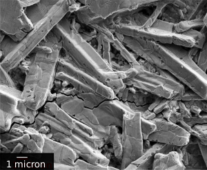
Figure 2: High magnification photograph of a galvannealed steel surface. The surface structure results in excellent paint adhesion.
Galvannealed coatings provides excellent corrosion protection to the underlying steel, as do GI and EG coatings. GI and EG coatings are essentially pure zinc. Zinc acts as a sacrificial anode if scratches or impact damages either coating, and therefore will corrode first before the underlying steel. The corrosion product of GI and EG is white, and is a combination of zinc carbonate and zinc hydroxide. A similar mechanism protects GA coated steels, but the presence of iron in the coating may result in a reddish tinge to the corrosion product. This should not be interpreted as an indication of corrosion of the steel substrate.
Another option is to change the bath composition such that it contains proper amounts of aluminum and magnesium. The results in a zinc-magnesium (ZM) coating, which has excellent cut edge corrosion protection.
Producing galvanized and galvannealed Advanced High Strength Steels is challenging due to the interactions of the necessary thermal cycles at each step. As an example, the targeted microstructure of Dual Phase steels can be achieved by varying the temperature and time the steel strip passes through the zinc bath, and can be adjusted to achieve the targeted strength level. However, not all advanced high strength steels can attain their microstructure with the thermal profile of a conventional hot dipped galvanizing line with limited rapid quenching capabilities. In addition, many AHSS grades have chemistries that lead to increased surface oxides, preventing good zinc adhesion to the surface. These grades must be produced on a stand-alone Continuous Annealing Line, or CAL, without an in-line zinc pot. Continuous Annealing Lines feature a furnace with variable and rapid quenching operations that enable the thermal processing required to achieve very high strength levels. If corrosion protection is required, these steel grades are coated on an electrogalvanizing line (EG) in a separate operation, after being processed on a CAL line.
Hot dipped galvanizing lines at different steel companies have similar processes that result in similar surfaces with respect to coefficient of friction. Surface finish and texture (and resultant frictional characteristics) are primarily due to work roll textures, based on the customer specification. Converting from one coating line to another using the same specification is usually not of major significance with respect to coefficient of friction. A more significant change in friction is observed with changes between GI and GA and EG.
Electrogalvanized Coatings
Electrogalvanizing is a zinc deposition process, where the zinc is electrolytically bonded to steel in order to protect against corrosion. The process involves electroplating: running an electrical current through the steel strip as it passes through a saline/zinc solution.
Electrogalvanizing occurs at room temperature, so the microstructure, mechanical, and physical properties of AHSS products achieved on a continuous anneal line (CAL) are essentially unchanged after the electrogalvanizing (EG) process. EG lines have multiple plating cells, with each cell capable of being on or off. As a result, chief advantages of electrogalvanizing compared to hot dipped galvanizing include: (1) lower processing temperatures, (2) precise coating weight control, and (3) brighter, more uniform coatings which are easier to convert to Class A exposed quality painted surfaces.
The majority of electrogalvanizing lines can apply only pure (free) zinc coatings, known as EG for electrogalvanized steel. Selected lines can apply different types of coatings, like EGA (electro-galvanneal) or Zn-Ni (zinc-nickel).
There are no concerns about different alloy phases in the coating as with galvanneal coatings. The lack of aluminum in the coating results in improved weldability. The biggest concern with electrogalvanizing lines is the coefficient of friction. Electrogalvanized (EG) coatings have a relatively high coefficient of friction – higher than hot dipped galvanized coatings, but lower than galvanneal coatings. To improve formability of electrogalvanized sheets, some automakers choose to use a steel mill-applied pre-lube rather than a simple mill-applied rust preventive oil.
A representative EG line is shown in Figure 3. Different EG lines may use different technologies to apply the zinc crystals. Because the zinc crystals are deposited in a different fashion, these different processes may potentially result in different surface morphology and, in turn, a different coefficient of friction. Dry conditions may result in a higher coefficient of friction, but the “stacked plate-like surface morphology” (Figure 4) allows these coatings to trap and hold lubrication better than the smoother surfaces of hot dipped galvanizing coatings. Auto manufacturers should therefore consult the steel supplier for specific lubricant recommendations based on the forming needs.

Figure 3: Schematic of an electrogalvanizing line.
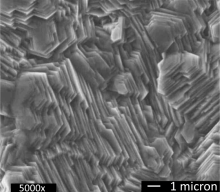
Figure 4: High magnification photograph of electrogalvanized steel surface showing stacked plate-like structure.
Zinc-Magnesium (ZM) Coatings
Galvanized coatings offer excellent corrosion protection to the underlying steel. Each type of galvanized coating has characteristics that make it suitable for specific applications and environments. The method by which the galvanization occurs (electrolytically applied vs. hot dipping) changes these characteristics, as does the coating chemistry (pure zinc vs. zinc alloy)
Adding small amounts of magnesium and aluminum affects the coating properties, which influences friction, surface appearance, and corrosion among other parameters.
Industries like agriculture and construction have used a coating known as ZAM for several decades. ZAM (Zinc-Aluminum-Magnesium) is primarily zinc, with approximately 6% Al and 3% Mg. However, the high aluminum content does not lend itself to a continuous galvanizing operation due to increased dross formation. The coating aluminum also degrades weldability.
A different coating, known as ZM, was commercialized around 2010. This zinc-rich coating typically has 1% to 3% of both magnesium and aluminum, with some companies using a slightly higher amount of aluminum. ZM coatings are typically applied using a hot dip approach like GI and GA, but with an appropriate bath chemistry. Exposed quality surfaces are achievable.
Even though ZM is a relatively hard coating, it is associated with lower friction and lower risk of galling and powdering than other common zinc coatings. This allows for parts to be successfully formed using higher blank holder forces, resulting in a wider BHF range between wrinkles and splits.Z-6
ZM coatings have similar joining characteristics and similar performance after phosphating / painting as hot dip galvanized coatings.
Enhanced cut edge corrosion protection relative to EG, GI, and GA coatings occurs due to the formation of a stable passivation layer on the bare steel edge that would be otherwise exposed to the environment. ZM coating corrosion dynamics are such that similar performance to EG, GI, and GA can be achieved at lower ZM coating weights.
Powdering resistance of ZM coatings are similar to that for GI and EG, and better than what is seen on GA coatings. ZM coatings have superior cyclic, perforating, and stone chip corrosion resistance.
Potential areas of application applications include:
- Hem flanges of doors, deck lids, and hoods
- Cut edges in inner hood, door, and deck lid panels
- Stone chip sensitive parts like hoods, fenders, doors, and body sides.
- Difficult to form parts that can benefit from the lower friction
Back to the Top
- Hot Dip Galvanized and Galvannealed Coatings
- Electrogalvanized Coatings
- Zinc-Magnesium (ZM) Coatings