
Formability
Strength is defined as load divided by cross-sectional area. In a tensile test, the choice of when the cross-sectional area is measured influences the results.
It is easiest to measure the width and thickness of the test sample before starting the pull. At any load, the engineering stress is the load divided by this initial cross-sectional area. Engineering stress reaches a maximum at the Tensile Strength, which occurs at an engineering strain equal to Uniform Elongation. After that point, engineering stress decreases with increasing strain, progressing until the sample fractures.
However, metals get stronger with deformation through a process known as strain hardening or work hardening. As a tensile test progresses, additional load must be applied to achieve further deformation, even after the “ultimate” tensile strength is reached. Understanding true stress and true strain helps to address the need for additional load after the peak strength is reached.
During the tensile test, the width and thickness shrink as the length of the test sample increases. Although these dimensional changes are not considered in determining the engineering stress, they are of primary importance when determining true stress. At any load, the true stress is the load divided by the cross-sectional area at that instant.
The true stress – true strain curve gives an accurate view of the stress-strain relationship, one where the stress is not dropping after exceeding the tensile strength stress level.
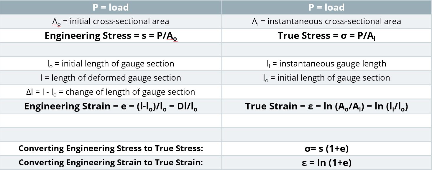
- True stress is determined by dividing the tensile load by the instantaneous area.
- True strain is the natural logarithm of the ratio of the instantaneous gauge length to the original gauge length.
True stress – true strain curves of low carbon steel can be approximated by the Holloman relationship:
σ = Kεn
where true stress = σ; true strain = ε, n is the n-value (work hardening exponent or strain hardening exponent), and the K-value is the true stress at a true strain value of 1.0 (called the Strength Coefficient).
True stress-strain curves obtained from tensile bars are valid only through uniform elongation due to the effects of necking and the associated strain state on the calculations. Inaccuracies are introduced if the true stress-true strain curve is extrapolated beyond uniform strain, and as such a different test is needed. Biaxial bulge testing has been used to determine stress-strain curves beyond uniform elongation. Optical measuring systems based on the principles of Digital Image Correlation (DIC) are used to measure strains. The method by which this test is performed is covered in ISO 16808.I-12
Stress-strain curves and associated parameters historically were based on engineering units, since starting dimensions are easily measured and incorporated into the calculations. True stress and true strain provide a much better representation of how the material behaves as it is being deformed, which explains its use in computer forming and crash simulations. Although sample dimensions are challenging to measure during a tensile test, there are equations that relate engineering units to true units. Conventional stress-strain curves generated in engineering units can be converted to true units for inclusion in simulation software packages.
Relationships Between Engineering and True Properties
More information about the differences between Engineering and True stress-strain curves can be found in the video below, and this blog entry.
Formability
Most sheet metals have different “Global” and “Local” forming capabilities, so it is critical to understand their meaning to optimize grade selection, processing, and usage.
Historically, most fabricators needed to consider only global formability when designing and stamping parts. Drawing, plane-strain tension, and stretch forming are “global” forming modes where deformation occurs in the plane of the sheet over relatively large regions of material. Tensile failures or necking failures, where the steel progressively thins during forming, are a characteristic of global formability failures. The strains across a stamped part start low and evenly distributed but begin to concentrate as the punch approaches bottom-dead-center. Critical thinning (also called necking) occurs if the strains induced by the part shape and forming process exceed the forming limit of the chosen sheet metal. Forming simulation software packages have reliably shown the ability to accurately predict global formability concerns and hot spots with the use of inputs like tensile test data and the correct forming limit curve.
Local formability failure modes are an entirely different failure condition, where fractures occur out of the plane of the sheet in response to concentrated deformation created when forming localized features like stretch flanges, extruded holes, or bends around a radius too small for the selected steel grade. These failures typically occur without any observable thinning or necking (Figure 1). Forming simulation software that considers only the forming limit curve or maximum thinning as the failure criteria cannot predict local formability failures.
Figure 1: A fracture related to insufficient local formability. Note the lack of thinning near the fracture. H-5
Cutting conditions and edge stresses developed in blanking and slitting operations play a significant role in limiting local formability. Trim steel clearances, shear angles, trim steel materials, tool sharpness and design, steel rolling direction, and part design considerations are all important (Figure 2).
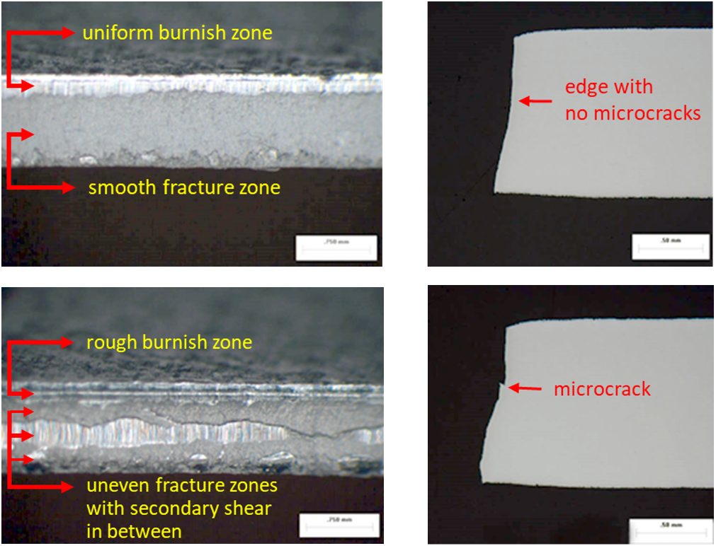
Figure 2: Cut edge uniformity influences edge quality.U-6
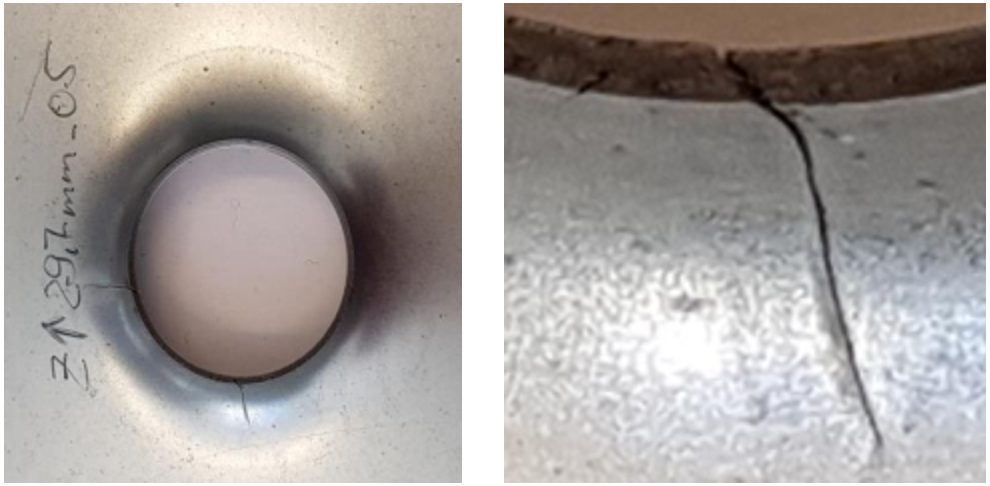
The absence of global thinning leading to the onset of localized necking highlights the importance of clearly defining the actual mode of failure before trying to identify possible solutions. Examination of the edge of the part where the failure is occurring is the best way to accomplish this. Figure 3 shows a photo of a typical local formability related edge fracture where no observable thinning/necking before fracture occurs.
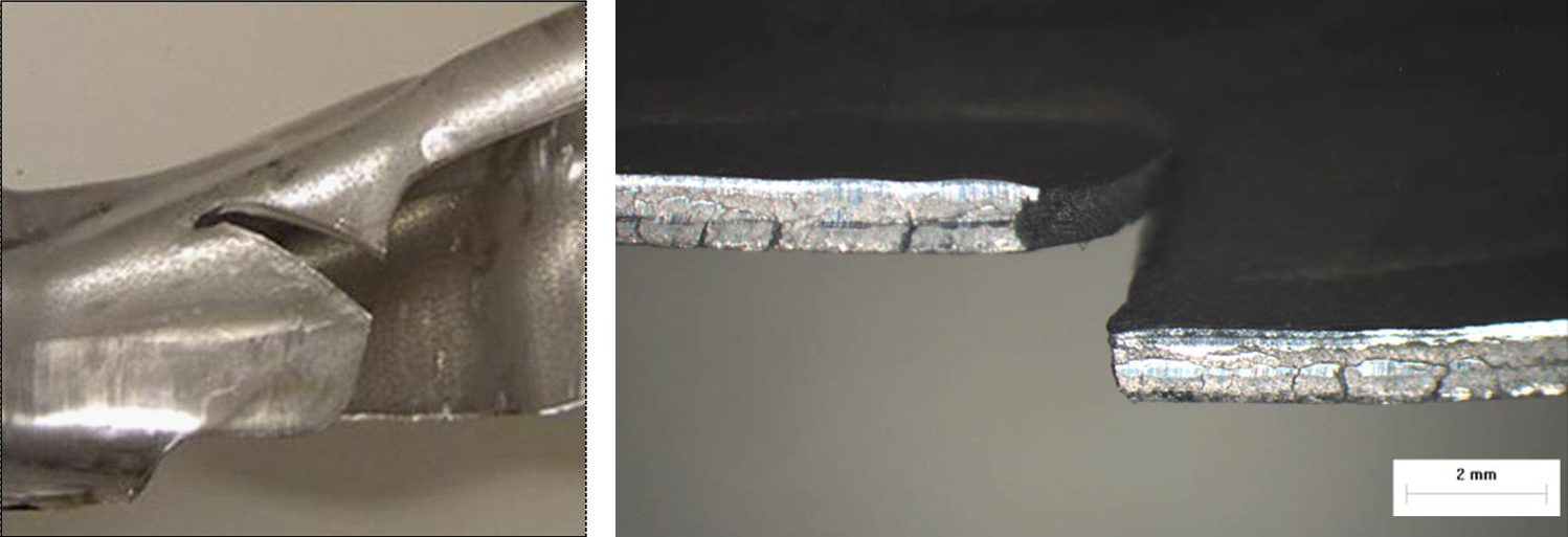
Figure 3: A typical local formability edge fracture viewed from different angles, with no appreciable thinning prior to fracture.U-6
Some AHSS grades are more prone to these local formability failures. A reduced hardness difference between microstructural phases appears to improve local formability. At a given tensile strength level, there may be grades with improved global formability, improved local formability, or a balanced approach available. Choosing the optimum grade requires understanding of the manufacturing die process and the functionality requirements associated with the part and its application.
Figure 4 shows an edge fracture on a DP980 rocker panel. This panel experienced edge fractures during production, occurring in embossments along the edge of the part, with no evidence of necking at the fracture site. This is a classic local formability failure, reinforcing the need to inspect the conditions at the fracture zone of AHSS to determine whether the root failure is global or local formability. Process and die solutions differ based on the mode of failure.

Figure 4: Classic local formability related edge fracture on an embossment within a DP980 part.U-6
Grade dependency is highlighted in Figure 5, which compares edges of HSLA 50SK on the left and DP500Y/780T on the right after stretch-bend testing under conditions to produce fracture. The HSLA sample shows the characteristic thinning down associated with necking. The DP steel did not have a visible neck at the failure location.S-11
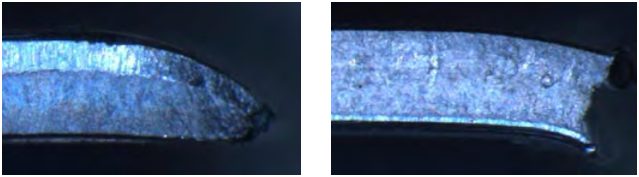
Figure 5: Left: HSLA 50SK, showing thinning at the fracture location, which is typical for global formability failures. Right: DP 500Y/780T, showing no thinning at the fracture location, which is typical for local formability failures.S-11
Mechanical tests now being employed to better quantify and characterize the unique local formability related failure modes associated with AHSS include:
Fracture-Limited Formability = Local Formability
In general, most sheet metal stamping failures result from exceeding the necking limit, and are termed global formability failures. However, there are important conditions which promote fracture before first developing a neck. These are of particular concern since such fractures cannot be predicted or anticipated based on conventional FLC and grid strain analysis techniques. Recent advances in metal forming software codes now allow input of appropriate data which substantially aids in these efforts. Still, there is no universally accepted shape of the Fracture Limit Curve.
Local Formability: Bending
Researchers discovered that all the steel through the sheet thickness must exceed the forming limit for necking to begin. In tight bends where the inner surface is compressed, strains never reach the critical strains in the conventional forming limit curve, which is why necking is not seen on the outer bend surface above a critical r/t level, or the ratio between the radius and the thickness.
However, as strength increases, the fracture limit is closer to the necking limit determined by the FLC. Advanced High Strength Steels are even more sensitive to local formability failures due to the localization of strains which occur at the interface between hard and soft phases in the microstructure.
On thin, wide sheet, bending strains on the metal surface plot along the axis of plane strain. The Fracture Limit Curve in this location is higher than the necking Failure Limit Curve, but since the critical strains only need to be reached on the outermost surface, higher-strength steels have a greater risk of experiencing bending fractures. In these cases, the material fracture limit becomes the effective forming limit in deformation modes with severe through-thickness strain gradients, and this is not considered in the traditional FLD.
Local Formability: Sheared Edge Expandability (Hole Expansion)
In a hole expansion test, the strains at the edge of the expanding hole follow a uniaxial strain path until reaching the fracture limit. In lower-strength steels with clean, machined (undamaged) edges, expansion ratios over 300% might be possible. As mentioned above, higher-strength steels have a lower fracture limit. Still, undamaged machined edges provide the best conditions for high hole expansion.
Cutting operations like blanking, shearing, and punching all damage the edge and lowers the fracture limit, meaning that the fracture limit might be reached at even lower strains. Strain localization occurring at the interface between hard and soft microstructural phases highlight why some grades have still lower critical strains.
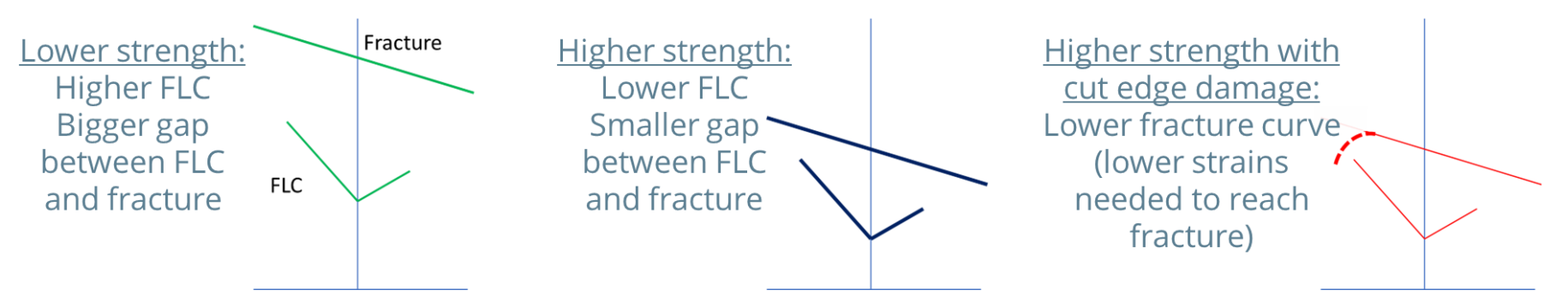
Figure 6: Higher-strength steels have a smaller gap between the necking Forming Limit Curve and the Fracture Limit Curve.
Summary of Global Formability
- The resistance to localized thinning (necking) is the key to global formability.
- Stamped parts get progressively thinner as the press stroke approaches bottom-dead-center. Rapid thinning in critical areas lead to the onset of localized necking. Global formability promotes the ability to reach deeper draw depths before initiation of necking.
- Measures of global formability include the work-hardening exponent (n-value), the uniform elongation value, and the total elongation value determined in a tensile test, along with the forming limit curve (FLC).
- Global formability failures occur when a through-thickness volume of the formed sheet steel exceeds this forming limit and begins to neck.
Necking failure typically should not occur if the global formability limit is exceeded on only the outer surface of steel bent over a radius or expanded at a cut edge and not through the full thickness of the metal.
- Uniform elongation measures the resistance to local necking. The global formability limit corresponds to Uniform Elongation in the strain state achieved in a tensile test sample. The Forming Limit Curve (FLC) encompasses all strain states.
- For mild and conventional high strength steels, there is a large difference between the necking limit and the ultimate fracture limit. This corresponds to the difference between Uniform Elongation and Total Elongation in a tensile test, where the value of total elongation is typically twice that of uniform elongation.
Summary of Local Formability
- The resistance to fracture is the key to local formability.
- Local formability promotes fracture resistance in response to creating local product features like stretch flanges, extruded holes, and tight-radius bends.
- Local formability tests which evaluate the stretchability of appropriately prepared edges by deforming them with a punch may have limited reproducibility between labs due to the influence of different sample preparation methods. Determining parameters like True Fracture Strain, Reduction in Area at Fracture, or Thickness Strain at Fracture with a well-defined tensile test typically results in repeatable and reproducible values.
- Local formability failure occurs when strains at the surface or edge exceed the ultimate fracture limit, a value that is higher than the necking limit determined by the Forming Limit Curve.
- Local formability failures occur more frequently on higher strength steels partly because of a smaller difference between the necking limit determined by the Forming Limit Curve and ultimate fracture limit.
- Work hardening and damage from edge preparation methods like shearing further reduce edge formability to values typically lower than indicated by the Forming Limit Curve, especially for AHSS. The strain localization at the interface between hard and soft phases in AHSS also contribute to an increased risk of local formability failures.
- The lack of a localized neck is a characteristic trait associated with of local formability failures.
Testing and Characterization
Delayed cracking caused by hydrogen embrittlement results in decreased toughness, ductility, and load-bearing capacity of a material. It is a concern with some Advanced High-Strength steel (AHSS) grades.
Three triggers must be present for there to be an embrittlement risk:
- Use of a susceptible material, such as steel with tensile strength above approximately 1000 MPa and/or the presence of retained austenite in the microstructure,
- An environment or processing step where hydrogen is available to diffuse into the steel, and
- Presence of a high stress condition, either from forming or during product usage and life cycle.
The interaction between hydrogen and the steel crystallographic structure in the presence of these conditions limits the ability of the steel to deform under load. The steel part will fracture at a lower stress than is anticipated under other conditions. Of particular concern is that fracture may not occur at the time of stamping, since hydrogen can diffuse out of the lattice over time.
High strain areas on parts formed from AHSS are at increased risk for delayed cracking, since the distorted crystallographic lattice allows for an increased hydrogen solubility. Cut edges are especially troublesome, since the shearing operation work hardens the steel (increasing strength) and damages the microstructure (increasing strain).
AHSS grades that contain retained austenite are also at increased risk for delayed cracking from hydrogen embrittlement. Stamping strains provide the driving force for the TRIP effect, where austenite coverts to martensite. The austenite crystallographic lattice allows for increased hydrogen solubility, so the TRIP effect creates a hydrogen-rich high strength martensite – conditions that promote a greater risk of embrittlement.
Sources of hydrogen include:
- Breakdown of mill or press applied lubricants,
- Annealing or heat treating atmospheres, and
- Electrochemical operations in steel mills or vehicle production such as pickling, electrogalvanizing, welding, phosphate coating, and paint pretreatment, such as e-coating.
Actions to minimize the risk of hydrogen embrittlement includes not over-pickling the surface prior to coating (since pickling uses an acid), heat treating in dew-point controlled atmospheres (below -10 °C or even lower for higher strength grades), and using the e-coating operation as a means to degas the steel.
Global steelmakers take alloying and processing approaches that are specific to their particular infrastructure and equipment. The same grade from two different steelmakers will likely use different alloying approaches. This may lead to different hydrogen embrittlement risks, as well as different tensile property ranges. Use caution when switching suppliers for all AHSS grades.
The procedures to characterize delayed fracture resistance typically involve using a machined sample, pre-strained and placed in an acidic solution for a defined time. SAE J3215S-94 is one such procedure.
Note that cracking in simulative tests does not necessarily indicate that parts made from that material would crack in an automotive environment due to the specific conditions that need to be present for hydrogen embrittlement to occur. When selecting any AHSS, results from simulative tests should be considered in conjunction with the forming and processing history of the steel, the strain state of the formed and processed part, and the operating environment of the part.
Testing and Characterization
Many demands are placed on automotive body structures which influence the material selection process. The impact on safety, manufacturability, and longevity are among the most critical, with each of these balanced against cost and environmental concerns.
Formed sheet metal products experience a complex series of deforming, cutting, and joining before being placed in a body structure, where these components will be subjected to complex loading conditions during the product life cycle. Understanding the failure limits and the conditions which produce failure allows for the design of body structures which can withstand these demands.
Testing helps determine whether a metal is suitable for its intended use. Different tests characterize specific performance aspects. Historically, manufacturers relied on tensile testing to understand metal flow. However, new tests help us understand the behavior of new steel grades and their interactions more thoroughly with new manufacturing technologies.