![Complex Phase]()
1stGen AHSS, AHSS, Steel Grades
Complex Phase (CP) steels combine high strength with relatively high ductility. The microstructure of CP steels contains small amounts of martensite, retained austenite and pearlite within a ferrite/bainite matrix. A thermal cycle that retards recrystallization and promotes Titanium (Ti), Vanadium (V), or Niobium (Nb) carbo-nitrides precipitation results in extreme grain refinement. Minimizing retained austenite helps improve local formability, since forming steels with retained austenite induces the TRIP effect producing hard martensite.F-11
The balance of phases, and therefore the properties, results from the thermal cycle, which itself is a function of whether the product is hot rolled, cold rolled, or produced using a hot dip process. Citation P-18 indicates that galvannealed CP steels are characterized by low yield value and high ductility, whereas cold rolled CP steels are characterized by high yield value and good bendability. Typically these approaches require different melt chemistry, potentially resulting in different welding behavior.
CP steel microstructure is shown schematically in Figure 1, with the grain structure for hot rolled CP 800/1000 shown in Figure 2. The engineering stress-strain curves for mild steel, HSLA steel, and CP 1000/1200 steel are compared in Figure 3.

Figure 1: Schematic of a complex phase steel microstructure showing martensite and retained austenite in a ferrite-bainite matrix.

Figure 2: Micrograph of complex phase steel, HR800Y980T-CP.C-14

Figure 3: A comparison of stress strain curves for mild steel, HSLA 350/450, and CP 1000/1200.
DP and TRIP steels do not rely on precipitation hardening for strengthening, and as a result, the ferrite in these steels is relatively soft and ductile. In CP steels, carbo-nitride precipitation increases the ferrite strength. For this reason, CP steels show significantly higher yield strengths than DP steels at equal tensile strengths of 800 MPa and greater. Engineering and true stress-strain curves for CP steel grades are shown in Figure 4.
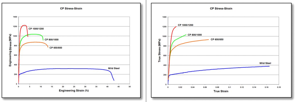
Figure 4: Engineering stress-strain (left graphic) and true stress-strain (right graphic) curves for a series of CP steel grades. Sheet thickness: CP650/850 = 1.5mm, CP 800/1000 = 0.8mm, CP 1000/1200 = 1.0mm, and Mild Steel = approx. 1.9mm.V-1
Whereas Dual Phase and TRIP steels excel at stretch forming and deep drawing, they are not as good in bending and cut-edge stretching. For applications needing these characteristics, complex phase steels are a good choice.
Table 1 compares galvannealed Dual Phase and Complex Phase steels having similar tensile strength and elongation as measured in a tensile test. The characteristics with the biggest difference are the yield strength and the hole expansion ratio which is a measure of cut-edge stretchability.
In the VDA-238 bending test, 980 DP exhibited a significant fracture with a bending angle of 67°. The 980 CP showed no fracture at 80°, and was capable of bending to over 100° before fracturing, Figure 5.N-33 The galvannealed 980 CP suppressed crack generation in axial crushing deformation to a much greater degree than the 980 DP.

Figure 5. Bendability of 980 DP (sample A) and 980 CP (sample B).N-33
Examples of typical automotive applications benefitting from these high strength steels with good local formability include frame rails, frame rail and pillar reinforcements, transverse beams, fender and bumper beams, rocker panels, and tunnel stiffeners.
Some of the specifications describing uncoated cold rolled 1st Generation complex phase (CP) steel are included below, with the grades typically listed in order of increasing minimum tensile strength and ductility. Different specifications may exist which describe hot or cold rolled, uncoated or coated, or steels of different strengths. Many automakers have proprietary specifications which encompass their requirements.
- ASTM A1088, with the terms Complex phase (CP) steel Grades 600T/350Y, 780T/500Y, and 980T/700Y A-22
- EN 10338, with the terms HCT600C, HCT780C, and HCT980C D-18
- VDA239-100, with the terms CR570Y780T-CP, CR780Y980T-CP, and CR900Y1180T-CPV-3
![Complex Phase]()
Forming Modes
top-of-page
The usual mode of bending is curvature around a straight-line radius (Figure 1). Through the thickness is a gradient of strains from maximum outer fiber tension (the outermost surface) through a neutral axis to inner fiber compression (the surface closest to the punch or bend axis). No strain occurs along the bend axis in the direction parallel to the bend axis, and therefore is in plane strain. The discussion below considers only bulk deformation, and excludes the implications of any edge effects. Bend testing procedures are linked here.

Figure 1: Typical bend where the outer surface is in tension, and the inner surface is in compression. A neutral axis lies in between.S-23
When sheet metal flows through draw beads or over the die radius into the punch opening, it is bent, straightened, and in the case of draw beads re-bent in the opposite direction. The net strain after this process may be relatively small. However, each of the sequential bending and unbending steps strain hardens the sheet metal, which reduces the ability for further deformation of the metal in subsequent operations.
Deformation at the outer surface during three-point bending depends on the stretchability capacity of the metal. The failure strain in the bend is related to the total elongation of conventional steel, but AHSS grades with multiphase microstructures such as DP and TRIP experience shear fracture that severely reduces the bendability before failure occurs. A higher total elongation helps sustain a larger outer fiber stretch of the bend before surface fracture, thereby permitting a smaller bend radius. Since total elongation decreases with increasing strength for a given sheet thickness, the minimum design bend radius must be increased (Figure 2).

Figure 2: Larger bend radius is needed as the total elongation decreases.S-23
The ratio of punch radius to sheet thickness, or the r/t ratio, allows for calculation of the amount of elongation on the outermost surface. This value can be compared against the total elongation of the metal as determined in a tensile test, or against the minimum elongation value allowed in the specification. If the part geometry will not allow for sufficient elongation for the selected metal grade, then either the part, process, or steel grade must change. [Note that this is not a perfect assessment, since elongation in a tensile test is measured relative to a 50 or 80 mm gauge length, which is likely different than the dimensions of the bent section.]
For design and springback control, usually a smaller r/t ratio is desirable. However, this may not be suitable in terms of formability. Increased material strength usually is associated with a reduction in total elongation, which in turn means a successful bend requires a larger r/t ratio.
For equal strengths, most AHSS grades have higher total elongations than conventional HSLA steels. However, several AHSS grades have limited local formability based on their microstructure, and may be at risk for cracking during edge expansion.
Cracking in production stamping conditions at stress levels below what is predicted with Forming Limit Diagrams may be attributed to these local formability failures. As an illustration, physical bend tests and simulations were performed for both HSLA and DP780 steels.S-11 The HSLA global formability failure aligned with simulation predictions (Figure 3), and was accompanied by a visible neck (Figure 4). In contrast, the DP780 showed no visible neck at the failure site (Figure 5) and no correlation between the simulation and actual test results (Figure 6).
Like hole expansion, bending limits in AHSS products are further lowered by shear fracture associated with the interfaces between the ductile ferrite and the hard martensite phase in the microstructure. This reduction becomes more severe as the strength increases, since increasing strength is achieved by increasing the volume of the hard martensite phase. More about shear fracture is found here.

Figure 3: Forming simulation of HSLA with strong correlation to actual testing.S-11

Figure 4: Close-up of visible necking before tensile failure in HSLA.S-11

Figure 5: Comparison of forming simulation with actual testing of the DP780. Note lack of correlation.S-11

Figure 6: Close-up of local formability failure on DP780 with no visible necking before failure.S-11
Rotary Bending
One way to address springback involves the use of rotary benders. Rotary benders transfer the vertical movement of a press stroke into a precise, rotary forming motion. A rocker or rotating die can simultaneously hold, bend, and overbend the sheet past 90° to counter material springback (Figure 7).
Figure 7: The rotation of the rocker bends the sheet metal around the anvil with less pressure than needed for wipe toolsD-8
Use rotary bending tooling where possible instead of flange wipe dies. Rotary bending allows for easy adjustment of the bending angle to correct for changes in springback due to variations in steel properties, die set, lubrication, and other process parameters. In addition, the tensile loading generated by the wiping shoe is absent.
There are four sequential steps to the process:
1) Downward pressure from the rocker clamps the part with the bending lobes before bending starts
2) Induced rotation of the rocker bends material around the anvil
3) The rocker bends the sheet metal past final angle to compensate for springback
4) The rocker releases the sheet metal to allow springback to desired angle
Using rotary benders to roll darts into the part during bending provides another way to reduce springback and stiffen the part (Figure 8).
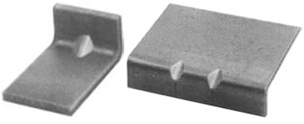
Figure 8: Stiffening darts can be created as part of the rotary bending operation.R-7
Back to the Top

Forming Modes
Stamping and die designers are interested in the forming capabilities of the steels they specify. Complex stampings are created from several different basic forming modes, which are sensitive to different mechanical properties. For this reason, steel formability, especially for AHSS grades, cannot be characterized by a single number, but instead must be done for each basic forming mode.
Forming modes and key points include:
Stretching
- Stretching is the sheet metal forming process where the punch which creates the part shape forces the sheet metal to thin since lock beads prevent metal flow inward from the flange area.
- The steel property that improves stretching is the strain hardening exponent, or n-value.
- Dome testing characterizes stretchability.
- Higher n-values flatten strain gradients, reduce localized thinning that leads to early failure, and allows the forming of more complex parts.
Bending
- Tensile testing cannot be used to determine bendability, since these are different failure modes. Different bend tests characterize bendability.
- The failure strain in the bend is related to the total elongation of conventional steel, but are limited by other issues in AHSS grades.
- For equal strengths, most AHSS grades have higher total elongations than conventional HSLA steels. However, several AHSS grades have limited local formability based on their microstructure, and may be at risk for cracking during edge expansion. AHSS grades with multiphase microstructures such as DP and TRIP experience shear fracture that severely reduces the bendability before failure occurs.
Drawing
- Drawing is the sheet metal forming process where the punch that creates the part shape forces the sheet metal to pull in from the flange area.
- The steel property that improves cup drawing or radial drawing is the normal anisotropy or rm value.
- The Limiting Draw Ratio (LDR) characterizes cup drawability.
- Higher r-value increases the LDR, but the absolute value of the LDR also depends on the lubrication, blank holder load, die radius and other system inputs.