High Energy Density Welding
Butt Welds and Tailor-Welded Products
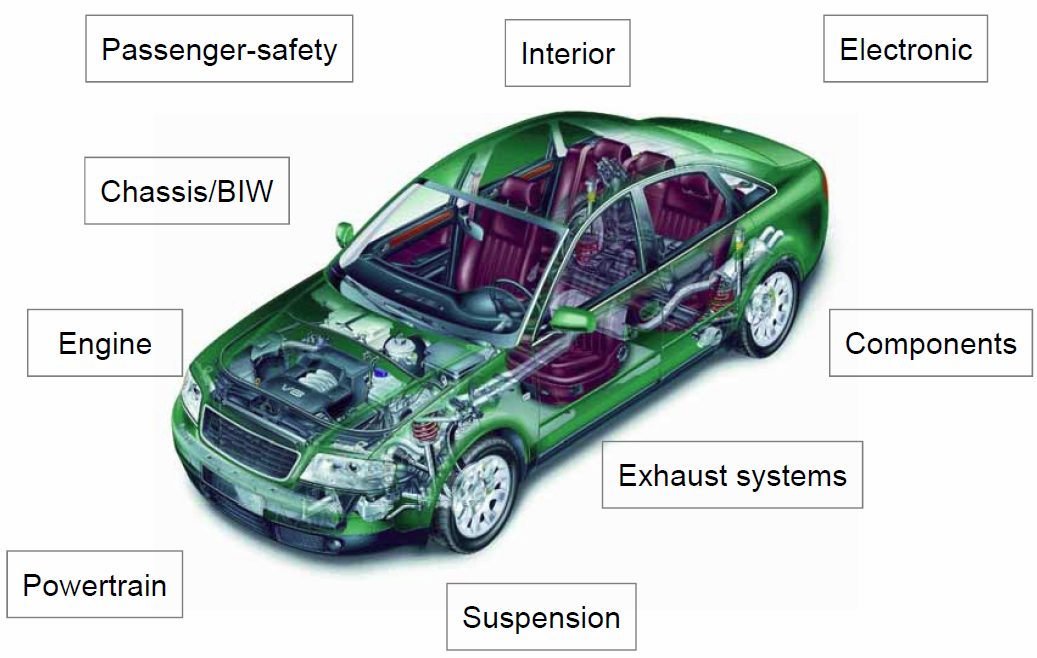
Figure 1: Common automotive applications using laser welding.T-9
AHSS grades can be laser butt-welded and are used in production of tailored products (tailor-welded blanks and tubes). The requirements for edge preparation of AHSS are similar to mild steels. In both cases, a good quality edge and a good fit-up are critical to achieve good-quality welds. The blanking of AHSS needs higher shear loads than mild steel sheets. (see Cutting in Blanking, Shearing and Trim Operations)
If a tailored product is intended for use in a forming operation, a general stretchability test such as the Erichsen (Olsen) cup test can be used for assessment of the formability of the laser weld. AHSS with tensile strengths up to 800 MPa show good Erichsen test values (Figure 2). The percent stretchability in the Erichsen test = 100 × the ratio of stretchability of weld to stretchability of BM.
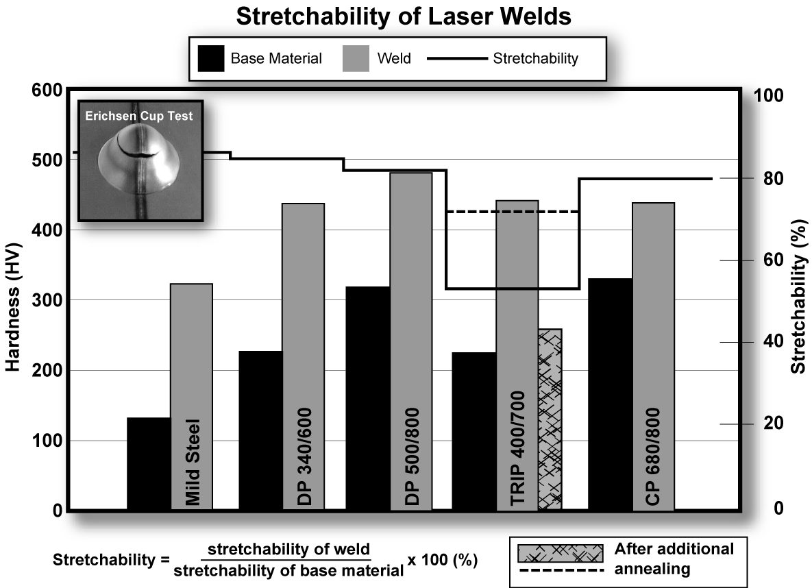
Figure 2: Hardness and stretchability of laser butt welds with two AHSS sheets of the same thickness (Erichsen test values describe the stretchability.B-1)
The hardness of the laser welds for AHSS is higher than for mild steels (Figure 3). However, good stretchability ratios in the Erichsen test can be achieved when the difference in hardness between weld metal and BM is only slightly higher for AHSS compared to mild steels. If the hardness of the weld is too high, a post-annealing treatment (using HF-equipment or a second laser scan) may be used to reduce the hardness and improve the stretchability of the weld.
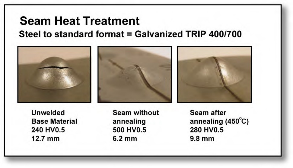
Figure 3: Improved stretchability of AHSS laser welds with an induction heating post-Heat treatment (Testing performed with Erichsen cup test.T-3)
Laser butt-welded AHSS of very high strength (for example Martensite steels) have higher strength than GMAW [LINK TO 3.2.1] welded joints. The reason is that the high CR in the laser welding process prompts the formation of hard martensite and the lower heat input reduces the soft zone of the HAZ.
Laser butt-welding is also used for welding tubes in roll-forming production lines as an alternative method for HF induction welding.
Assembly Laser Welding
Automotive applications use a variety of welding joint designs for laser welding in both lap joint and seam butt joint configurations as shown in Figure 4. Lap joints and seam butt joint configurations use different characteristics. Seam welds on butt joints need less power from the machine than lap joints due to the smaller weld fusion area, producing less distortion and a smaller HAZ. Butt joint configurations are more cost efficient. However, the fit up for seam welds can be more difficult to obtain than those of lap joints. Also, lap joints tend to provide a larger process window.
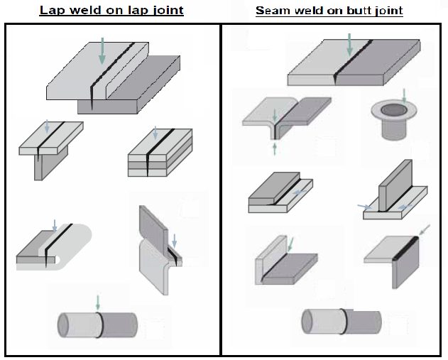
Figure 4: Common seam and joint types for laser welding of automotive applications.T-9
When seam welding butt joint configurations, a general guideline for fit-up requirements include a gap of 3-10% the thickness of the thinnest sheet being welding and an offset of 5-12% thickness of the thinnest sheet. A guideline for lap joints can require a gap of 5-10% the thickness of the top sheet being welded (Figure 5). These general guidelines are not absolute values due to the change of variables such as the focus spot size, the edge geometry for butt welds, strength requirements, etc.
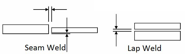
Figure 5: Fit-up requirements for butt joint and lap joint configurations in laser welding.T-9
Laser welding is often used for AHSS overlap joints. This type of weld is either a conventional weld with approximately 50% penetration in the bottom sheet or an edge weld. Welding is performed in the same way as for mild steels, but the clamping forces needed for a good joint fit-up are often higher with AHSS than for mild steels. To achieve good laser-welded overlap joints for Zn-coated AHSS, a small intermittent gap (0.1-0.2 mm) between the sheets is recommended, which is identical to Zn-coated mild steels. In this way, the Zn does not get trapped in the melt, avoiding pores and other imperfections. An excessive gap can create an undesirable underfill on the topside of the weld. Some solutions for lap joint laser welding Zn- coated material are shown in Figure 6.
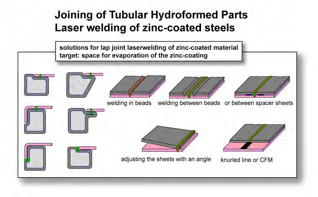
Figure 6: Laser welding of Zn-coated steels to tubular hydroformed parts.L-3
StudiesL-59 have shown welding Zn-coated steels can be done without using a gap between the overlapped sheets. This is accomplished using dual laser beams. While the first beam is used to heat and evaporate the Zn coating, the second beam performs the welding. The dual laser beam configuration combines two laser-focusing heads using custom-designed fixtures.
Remote Laser Welding
Remote scanner welding is used for many automotive applications, including seating (recliners, frames, tracks, and panels), BIW (trunks, rear panels, doors I hang on parts, side walls, and pillars) and interior (IP beams, rear shelfIhat rack) (Figure 7). Compared to conventional laser welding, remote scanner welding has several advantages. Those include a reduced cycle time (via reduction of index time), programmable weld shapes (ability to customize weld shape to optimize component strength), large stand-off (longer protection glass life), and reduced number of clamping fixtures (via reduced number of stations).
Remote laser welding, or “welding on the fly”, combines a robot and scanner optics to position the focused laser beam on the workpiece on the fly. The robot arm guides the scanner optics along a smooth path about half a meter over the workpiece. Extremely nimble scanning mirrors direct the focal point in fractions of a second from weld seam to weld seam. A fiber-delivered, solid-state laser is the source of the joining power far away from the processing station. The scanning optic or Programmable Focusing Optic (PFO) at the end of the laser’s fiber-optic cable is the central element for precise positioning of the laser’s focus point on the component to be welded. Inside the PFO, two scanner mirrors direct the beam through a “flat field” optic, which focuses the beam onto a common focus plane no matter where it is in the work envelope of the PFO. The PFO is also equipped with a motorized lens that allows the focus plane to be moved up and down in the Z-axis. The repositioning of the focused laser beam from one end of the entire work envelope to the other takes about 30 ms.T-9
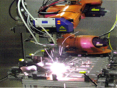
Figure 7: Remote laser welding of automotive applications.T-9
There are three basic preconditions for welding on the fly. First, a solid-state laser is needed as the beam source. Solid-state lasers enable delivery of the laser beam through a highly flexible fiber optic cable, which is required when joining components in 3D space with a multi-axis robot. Second, a laser with excellent beam quality and the appropriate power is required. Beam quality is the measure of focus-ability of a laser, and the long focal lengths required for remote welding necessitate superior beam quality (i.e., 4 to 8 mm-mrad) to achieve the appropriate focused spot size (i.e., about 0.6 mm) at the workpiece. For remote welding in automotive body production, typically about 4 to 6 kW of laser power is used. The third essential precondition is precise positioning of the weld seams, which requires axis synchronization between the robot and the scanner control. This allows the weld shape programmed in the scanner control for a specific shape weld to have proper shape with the robot moving at various speeds over the part to be welded. Some control architectures use “time” synchronization. The problem here is that if the robot speed is changed for any reason, the weld shape will also change because the axes are not synchronized.T-9
Body-in-White (BIW) Joining
Laser-based solutions can offer a high- and cost-effective improvement potential for steel-based BIW joining. The laser joining design’s stiffness increases in direct relation to the laser weld length. Also, at low process time, there is up to a +14% torsional stiffness increase without any additional joining technique, shown in Table 1.
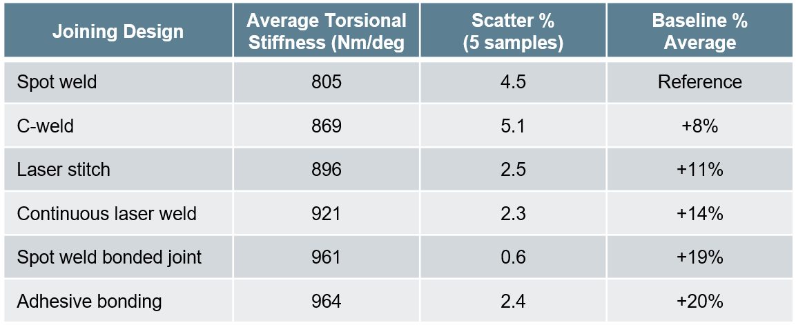
Table 1: Stiffness performances comparison for several joining designs.A-16
Laser weld shape optimization can help to homogenize performances and increasing the laser weld shape factor leads to a signification reduction of IF fracture risk (Figure 8).
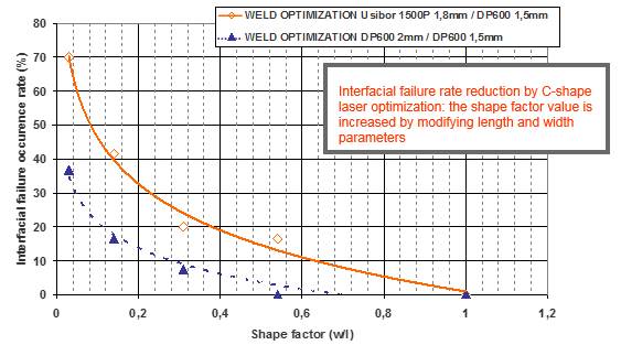
Figure 8: Impact of laser weld design optimization on fracture type.A-16
DP 800 (with additional retained austenite and associated bainite) has the advantage of weight reduction and equally good properties when laser welding as the DP 800. The absolute strength of DP 800 is slightly higher, but the ductility for the DP 800 is greater, shown in Figure 9.
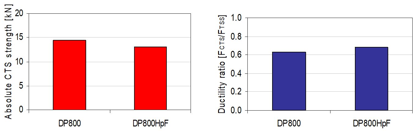
Figure 9: Absolute strength and ductility of DP 800 and DP 800.T-10
Figure 10 shows a cross-tension test in which both materials fail outside the weld zone, DP 800 failing entirely in the HAZ and DP 800 failing partly in the HAZ and partly in the BM.
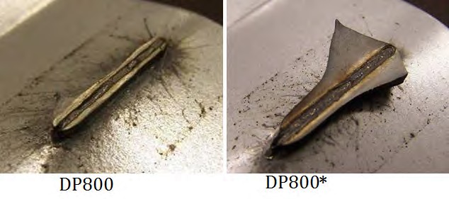
Figure 10: Cross-tension testing of DP 800 and DP 800.T-10
Figure 11 is the microhardness profile of 1.6-mm Q&P 980’s laser weld joint. Microhardness of both welded seam and HAZ are all higher than BM, and there is no obvious softened zone in HAZ.
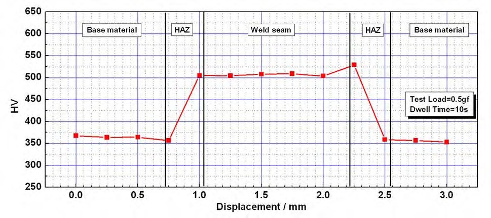
Figure 11: Microhardness profile of 1.6-mm Q&P 980’s laser weld joint.B-4
Figure 12 is Erichsen test result for the BM and weld seam of 1.6-mm Q&P 980, showing good stretchability.
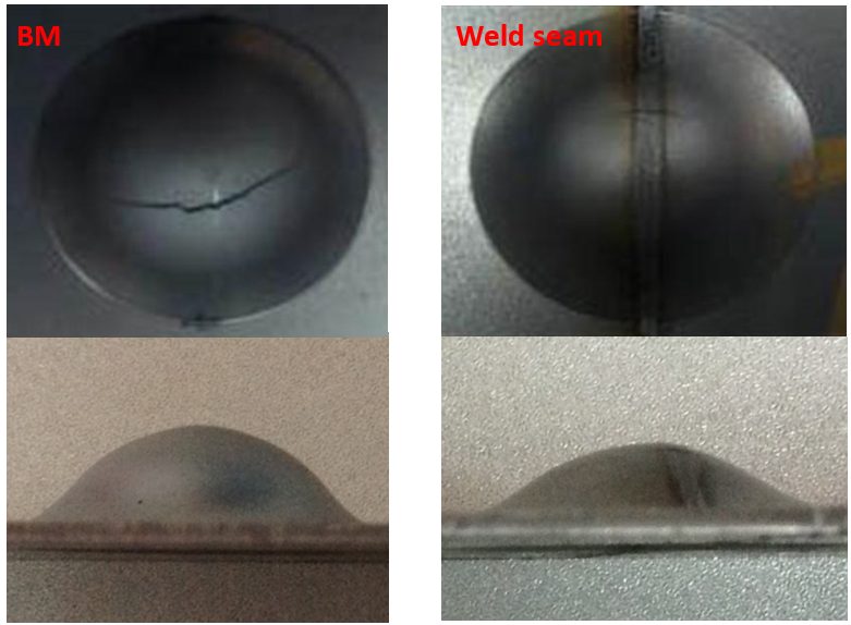
Figure 12: Erichsen test result of 1.6-mm Q&P 980, laser welded.B-4
Hybrid Laser and GMAW Welding
In hybrid welding process parameters such as stick out and torch angle are very important to decide overall joint performance. A model has been developed to predict the penetration and toe length under similar heat input conditions, shown in Figure 13. The gap, stickout and angle shows synergic agreement with penetration and toe length but the interactions among them can show disagreement.
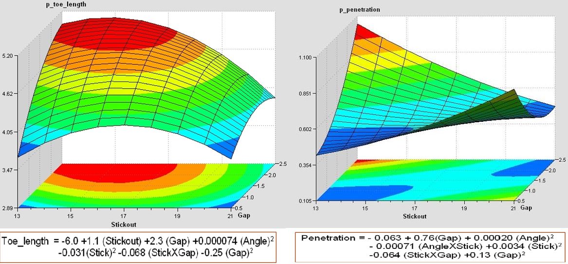
Figure 13: Effects of toe length and penetration.T-10
The weld joint strength increases with the increase in wire feed rate for a given laser power shown in Figure 14.
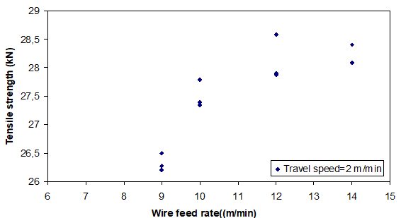
Figure 14: Wire feed rate versus tensile strength of hybrid laser and MIG welds.T-10
Back To Top
Adhesive Joining
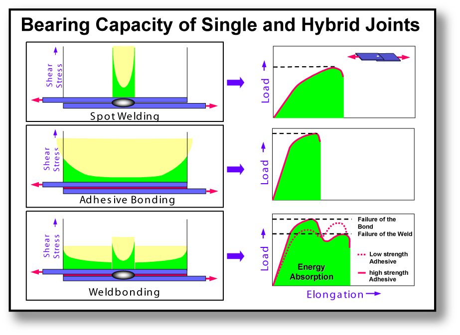
As with mild steels, AHSS-hybrid joints can be made by combining adhesive bonding with RSW, clinching, or self-piercing riveting. These hybrid joints result in higher strength values (static, fatigue, and crash) than the spot welding alone (Figure 1). If local deformation and buckling can be avoided during in-service applications of weld bonding/adhesive hybrid joining, the potential for component performance is enhanced.
Figure 1: Comparison of bearing capacity for single and hybrid Joints.B-3
Hybrid RSW and Adhesives
Many automotive joining BIW applications are using the combination of RSW together with adhesives to obtain superior joint performance. This combination is referred to as WB. Figure 2 shows a tensile shear test for resistance spot welds, adhesives, and weld bonds. There were trends of fracture strength increasing slightly with material strength with the spot welds. Also, the fracture strength was very high, increasing significantly with increasing material strength for adhesive bonds. The fracture strength was the highest for welded bonds and increased significantly with increasing material strength.
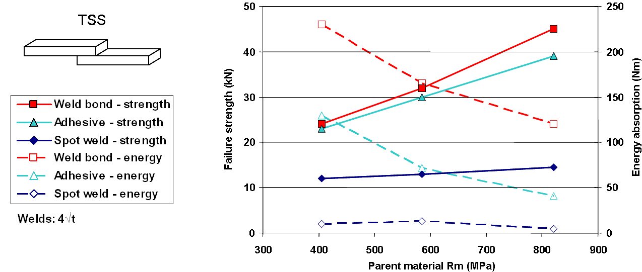
Figure 2: TSS failure strength and energy absorption for all joints and materials.T-10
Figure 3 represents a peel test for the same samples. Trends observed were fracture strength increasing slightly with material strength but is lower than the other joining methods for spot welds. Fracture strength for adhesive bonding is greater than Weld Bonding (WB) and spot welding. Energy absorption was not very sensitive to material strength. The bond using adhesive alone had poor failure strength as well as poor energy absorption.
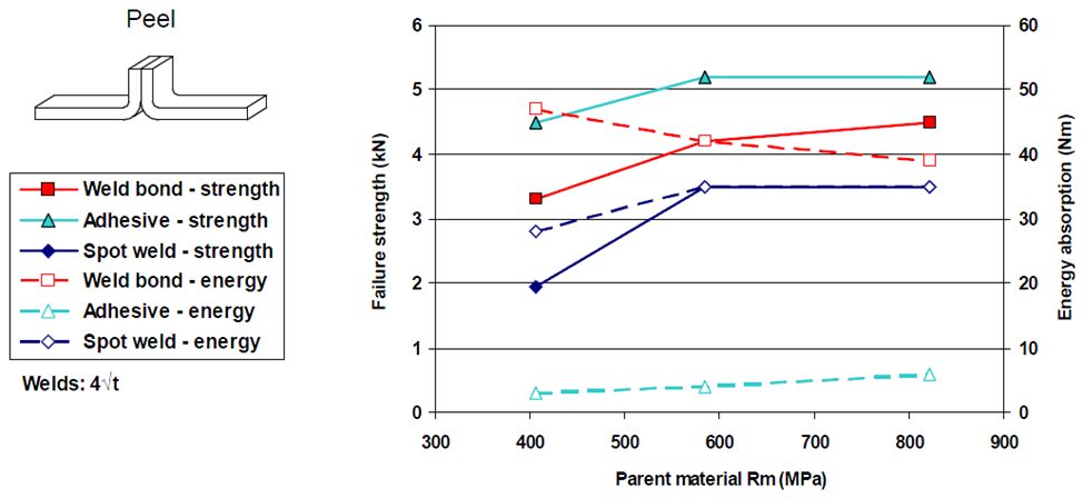
Figure 3: Peel strength data for all joint types.T-10
Figure 4 shows cross tensile results for the three samples. Spot welds showed fracture strength reaching a maximum for DP 600. Adhesive fracture strength increased slightly with increasing material strength. The welded bond’s fracture strength was greater than the other joint types and increased significantly with increasing material strength.
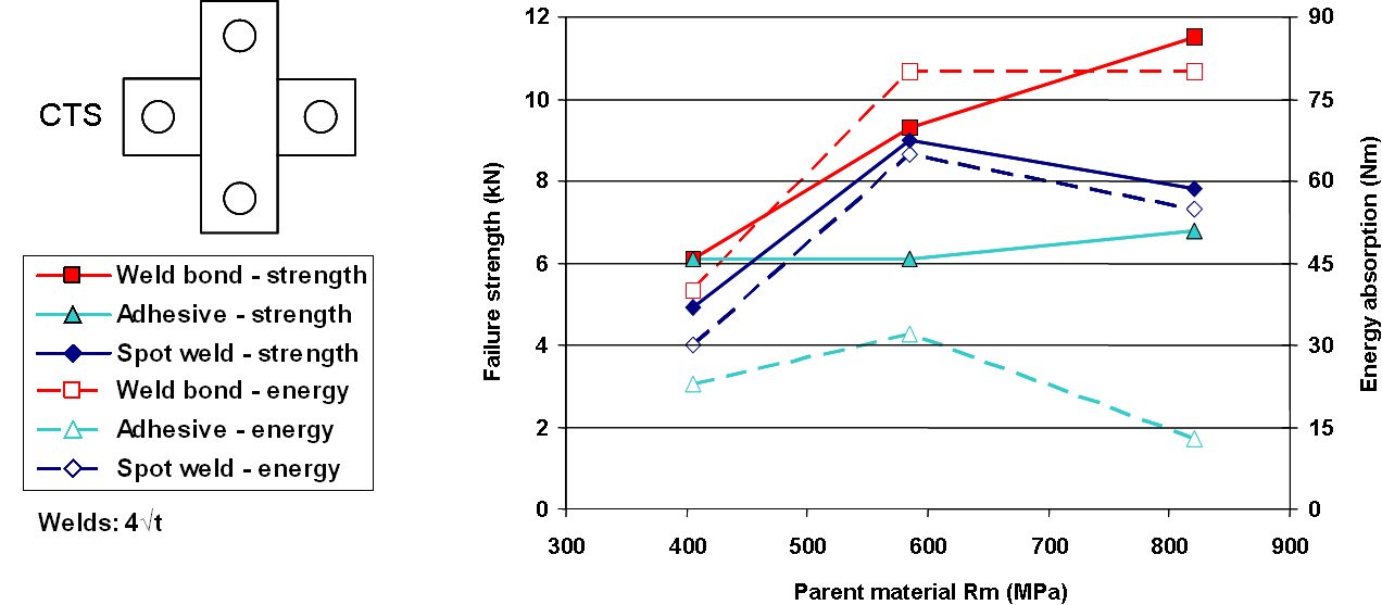
Figure 4: CTS fracture strength and energy absorption for all joints and materials.T-10
Figure 5 shows the fatigue testing performed in tensile shear mode on DP 800 [LINK TO DP steel page in Metallurgy] material (1.2-mm gage). Spot welds showed the lowest fatigue properties of the test samples. While the weld-bonded samples performed much better than conventional spot welds, they were still weaker than the adhesive joints. Adhesive had the best fatigue performance. The parent material properties had little influence upon the fatigue properties of spot welds because the spot weld itself acts as a fatigue crack initiator.
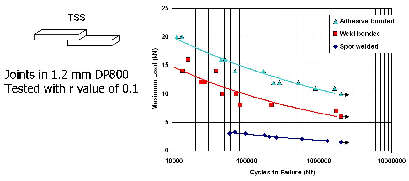
Figure 5: DP 800 fatigue results.T-10
RSW Modelling and Performance
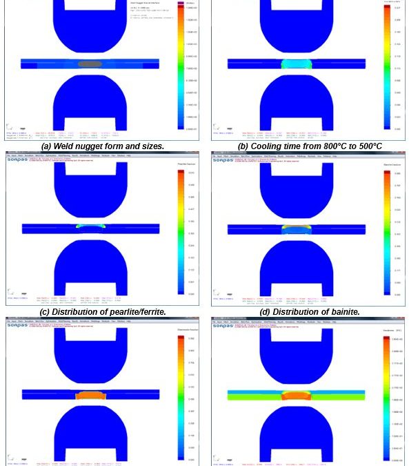
The advantages of numerical simulations for resistance welding are obvious for saving time and reducing costs in product developments and process optimizations. Today’s modeling techniques can predict temperature, microstructure, stress, and hardness distribution in the weld and Heat Affected Zone (HAZ) after welding. Commercial modeling software is available which considers material type, various current modes, machine characteristics, electrode geometry, etc. An example of process simulation results for spot welding of 0.8-mm DC 06 low-carbon steel to 1.2-mm DP 600 steel is shown in Figure 1. Obviously, this technique can apply to dissimilar thicknesses, material types, and geometries. Application of adhesives is also being used with these simulations. This simulation techniques are found to be very beneficial to predict vehicle crashworthiness as it can dramatically reduce the cost of crash evaluations.
You will find several articles in this section describing RSW modelling studies and procedures.
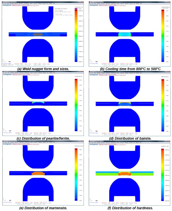
Figure 1: Simulation results with microstructures and hardness distribution for spot welding of 0.8-mm DC06 low-carbon steel to 1.2-mm DP 600 steel.Z-1

Arc Welding
Fundamentals and Principles of Arc Welding
This section serves as an introduction to all the arc welding processes. The common features and important concepts and terminology of this family of processes are reviewed, with more process-specific details provided in the sections covering the specific processes.
Arc welding refers to a family of processes that rely on the extreme heat of an electric arc to produce a weld. They may or may not rely on additional filler metal to create the weld. Although generally considered “low-tech”, arc welding continues to be very popular primarily due to its low equipment cost and high flexibility. Some of the key discoveries that led to modern arc welding include the discovery of the electric arc in the 1820s (Davies), the first welding patent using a carbon electrode in 1886, and the first covered electrode in 1900 (Kjellberg).
The most common arc welding processes today are illustrated in Figure 1. The abbreviations refer to American Welding Society (AWS)A-11 terminology as follows:
- EGW – Electroglas Welding
- FCAW – Flux-Cored Arc Welding
- GMAW – Gas Metal Arc Welding
- GTAW – Gas Tungsten Arc Welding
- PAW – Plasma Arc Welding
- SAW – Submerged Arc Welding
- SMAW – Shielded Metal Arc Welding
- SW – Arc Stud Welding
Figure 1: Common arc welding processes.
Whereas the welding engineer should always use proper AWS terminology during formal communications, in reality, the use of slang terminology for SMAW, GMAW, and GTAW processes is very common. Thus, where appropriate the “slang” terminology is included in italics.
With all arc welding processes, the initiation of an arc basically completes (or closes) an electrical circuit consisting of the ground and work cables, the welding torch, the workpiece or parts to be welded, and the secondary of the welding power supply. Voltages provided by the power supply are commonly either 60 or 80 V. Such voltages are high enough to establish and maintain an arc, but low enough to minimize the risk of electric shock. Once the arc is struck, actual arc voltages commonly range between 10 and 35 V. Direct Current (DC) is most common, but Alternating Current (AC) is sometimes used. Pulsed DC is becoming a common feature in modern welding power supplies. The electrical polarity used during arc welding is very important, but it has different effects with different processes. The effect of polarity on heat input is especially important with GTAW and GMAW, but the effects are opposite. With GTAW, direct-current electrode negative (DCEN) produces the greatest amount of heat into the part and is the most common polarity. However, with GMAW, direct-current electrode positive (DCEP) produces the greatest amount of heat into the part and is used almost exclusively with this process (Figure 2).
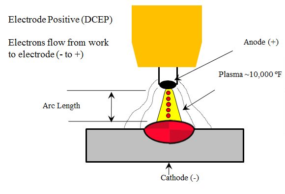
Figure 2: DCEP – common with GMAW.
The heat input during arc welding is primarily a function of weld travel speed and current, based on the following equation:

Although voltage appears to play a prominent role in the heat input equation, it is a parameter that is chosen primarily to create the most stable arc, not to affect heat input.
AWS filler metal classifications vary somewhat depending on the process. A common example is the classification system for SMAW electrodes, “EXXXX” where “E” stands for electrode, the two digits following the E give the minimum deposited weld metal tensile strength in kips per square inch (ksi) (there will be a third digit if the strength is 100 ksi or higher), the third “X” provides information on what welding positions that electrode can be used for, and the final “X” provides information about the coating type. The electrode and filler metal classification schemes will be covered in more detail in the subsequent chapters covering each of the arc welding processes.
Shielding
When metals are heated to high temperatures approaching or exceeding their melting point, diffusion rates are accelerated and the metals become very susceptible to contamination from the atmosphere. Elements that can be most damaging are oxygen, nitrogen, and hydrogen, and contamination from these elements can result in the formation of embrittling phases (such as oxides and nitrides), and porosity. To avoid this contamination, the metal must be shielded as it solidifies and begins to cool. The arc welding processes all rely on either a gas or a flux, or a combination of both for shielding. The way these processes are shielded is their main distinguishing feature from one another.
Processes such as GMAW, GTAW, and PAW rely solely on gas shielding. Shielding gasses protect by purging the susceptible metal from atmospheric gasses. The GMAW process commonly uses argon (Ar), carbon dioxide (CO2), or blends of Ar and CO2. CO2 gas produces more spatter and a rougher weld appearance. It can produce fast welding speeds, is readily available, and is cheap. Additions of CO2 or small amounts of O2 to Ar can improve puddle flow. The choice of shielding gas for GMAW plays a major role in the type of molten metal transfer mode from the electrode to the weld puddle.
Arc Welding Weld Joints and Types
The selection of a proper weld joint and weld type is a very important aspect of arc welding. The joint refers to how the workpiece or parts that are being welded are arranged relative to each other, and weld type refers to how the weld is formed in the joint. Specifically in arc welding, there are numerous joint types, but only two weld types, a fillet and a groove weld. A fillet weld offers the advantage of requiring no special joint preparation because the geometry of the joint provides the appropriate features to place the weld. Groove welds facilitate the creation of full-penetration welds which are often required in critical applications. The choice of weld and joint type is often dictated by the design of the component being welded but will play a major role in the properties of that joint. The thickness of the parts being welded, as well as the material and type of welding process being used may also affect the choice of weld or joint type. Some very common arc welding joints and weld types are shown in Figure 3. Basic welding positions are shown in Figure 4. It is recommended that all welding joints be positioned for welding in either the flat or horizontal position whenever possible. The horizontal or vertical plane of the flat and horizontal joint may vary up to a maximum of 10 degrees.
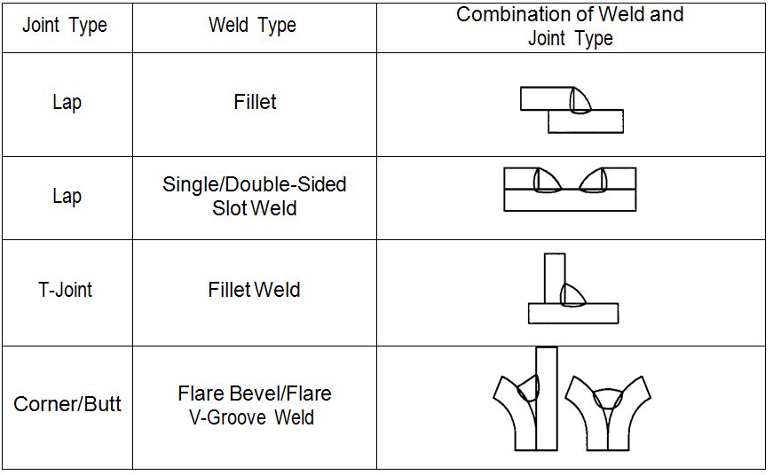
Figure 3: Typical arc welding joint and weld types for automotive sheet steel applications.
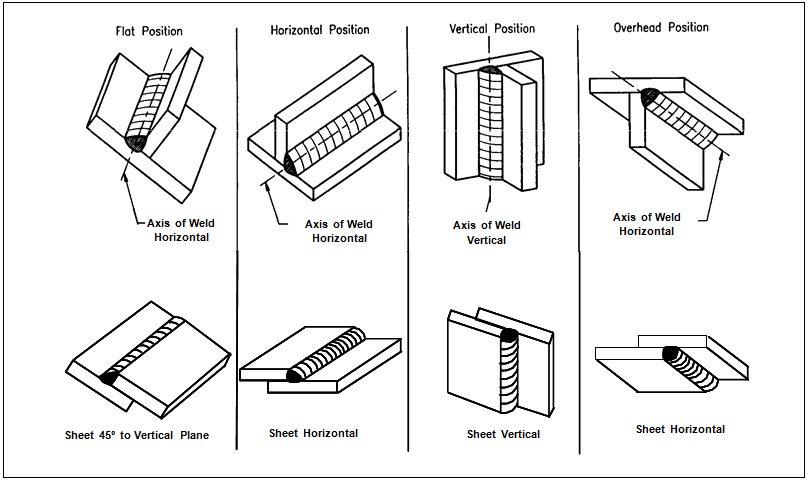
Figure 4: Basic arc welding positions.
Electrode Feed Rate
When using the semiautomatic arc welding processes such as GMAW electrode feed rate (or wire feed speed) determines both deposition rate and current. Higher feed rates increase weld metal deposition and increase current since melting rates at the end of the wire must increase as the wire feed speed increases. As a result, with the semiautomatic processes, current is typically adjusted by changing the wire feed speed since the two are relatively proportional. Typical wire feed speeds are between 100 and 500 inches per minute (ipm).
Welding Travel Speed
Travel speed refers to how fast the welding arc is moving relative to the workpiece. The heat input equation clearly shows that travel speed, like current, plays a direct role in the amount of heat into the part. Faster speeds produce less heat into the part and reduced weld metal deposit. The choice of travel speed is typically driven by productivity, with the obvious desire to usually weld as fast as possible. Travel speed is independent of current and voltage and may be controlled by the welder or mechanized. Typical travel speeds range between 5 and 100 ipm.
Arc Welding Safety
There are many hazards associated with arc welding that are not only important concerns for the welder, but for personnel working around any arc welding operations. This section will provide a very brief overview of the most common hazards of which the welding personnel should be aware. It is strongly recommended regarding safety in arc welding and other welding and associated processes to refer to the American National Standards Institute (ANSI) Document Z49.1, “Safety in Welding, Cutting, and Allied Processes”.
Ultraviolet radiation from the arc can damage the eyes and burn the skin in the same way skin is burned from the sun. This requires the use of proper shielding for the eyes and protective clothing to cover any exposed skin. Personnel working near arc welders should be careful not to glance at an open arc without proper shielding. Sparks and spatter during welding mandate the need for proper eye protection for anyone near the welding operation. Additional protective helmets are needed for the welder. Although the low voltages used in arc welding are relatively safe, proper electrical safety must be exercised at all times, including grounding of parts and equipment and avoiding damp conditions.
Welding fumes can be hazardous to the welder when inhaled over long periods of times so proper ventilation is paramount. Shielding gases can produce suffocation in enclosed spaces, such as when welding in tanks. Ar is heavier than air, and in the absence of proper ventilation, will displace oxygen when it fills a room. Helium is lighter than air producing a similar risk for overhead welding. Compressed shielding gas bottles can explode when mishandled or abused, or an arc strike can weaken the bottle, leading to an explosion. Hot metal is always a hazard with fusion welding processes like arc welding. When working around a welding operation, one should always assume that any piece of metal is hot. Welding arcs and associated hot metal spatter are ready sources for ignition of flammable materials in the vicinity of welding. Many fires have been started by careless welders who are not aware of any combustible material.A-11, P-6
Arc Welding Procedures
Conventional arc welding (for example GMAW, TIG, and plasma) can be used for AHSS in a similar way to mild steels. The same shielding gases can be used for both AHSS and mild steels. For automotive applications, a design gap tolerance (G) of 0-0.5 mm is allowed for all weld joints, as illustrated in Figure 5. An edge trim tolerance (Et) of ±0.5 mm is required where the edge is part of the weld joint, as shown in Figure 6. The variation in edge location causes variation in alignment of the electrode wire with the weld joint, as shown in Figure 6. Misalignment of the electrode may cause poor weld shape, improper fusion and burn-though. To control this variable, the trim tolerance at the weld joint must be held to ±0.5 mm and the electrode must maintain a root joint alignment tolerance of ±0.5 mm.
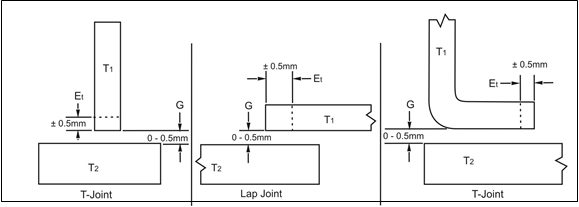
Figure 5: Joint design tolerance.A-12
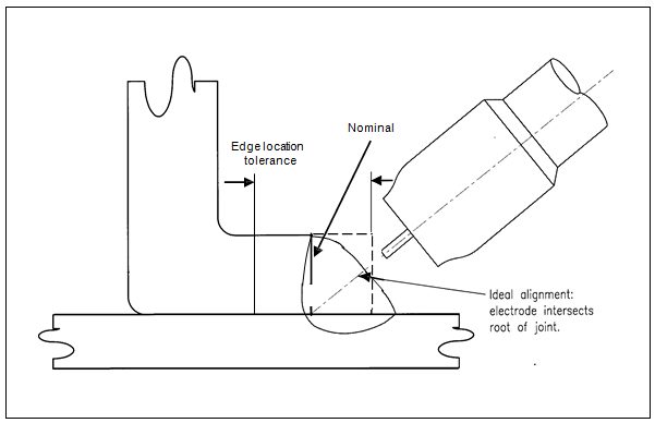
Figure 6: Edge location tolerance for fillet weld in a lap joint.A-12
A tolerance stack-up review must be performed on all GMAW joints. The worst-case maximum designed gap including tolerance stack-up shall not exceed what is listed in Figure 7. It is preferable to target the smallest possible gap (the thickness of the thinnest sheet or 1.5 mm, whichever is smaller). High-stress areas defined by CAE analysis and/or functional testing should be reviewed for weld optimization. Figure 8 illustrates techniques used to reduce the fillet weld stress concentration and to improve weld performance. These techniques include placing the weld start/stop away from corners and other high-stress areas, avoiding abrupt weld line direction changes when possible, etc.
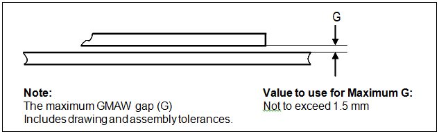
Figure 7: Maximum GMAW welding gap.A-12
Intermittent welds that are properly sequenced can help keep joints closed by reducing the heat input which reduces distortion. Meanwhile, intermittent welds also introduce weld starts and weld stops, both of which are stress risers. Similar to continuous welds, weld start/stops of intermittent welds should be placed away from high stress areas. Intermittent welds are specified by the center-to-center distance (i.e., pitch) and weld length, as shown in Figure 9.
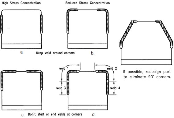
Figure 8: Reducing weld stress concentrations.A-12
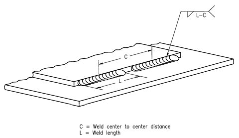
Figure 9: Intermittent fillet weld spacing.A-12
Despite the increased alloying content used for AHSS, there are no increased welding imperfections compared with mild steel arc welds. Changing from mild steel to AHSS may also result in a change of arc blow. The strength of the welds for AHSS increases with increasing base metal strength and sometimes with decreasing heat input. Depending on the chemical composition of AHSS [for example, mild Steels and DP steels with high martensite content and strength levels more than 800 MPa], the strength of the weld joint may be reduced in comparison to the base metal strength due to small soft zones in HAZ (Figure 10). For CP and TRIP grades, no soft zones occur in HAZ due to the higher alloying content for these steels in comparison to DP and mild steels.

Figure 10: Relationship between martensite content and reduction in true ultimate tensile strength (UTS) (Data obtained by thermomechanical simulation of high heat input GMAW HAZ.D-1).
Higher strength filler wires are recommended for welding of AHSS grades with strength levels higher than 800 MPa (Figure 11 for single-sided welded lap joint and Figure 12 for butt joints). It should be noted that higher strength fillers are more expensive and, more importantly, less tolerant to the presence of any weld imperfections. When welding AHSS to lower strength or mild steel, it is recommended that filler wire with 70 ksi (482 MPa) strength be used. Single-sided welded lap joints are normally used in the automotive industry. Due to the asymmetrical loading and the extra bending moment associated with this type of joint, the strength of this lap joint is lower than that of the butt joint.
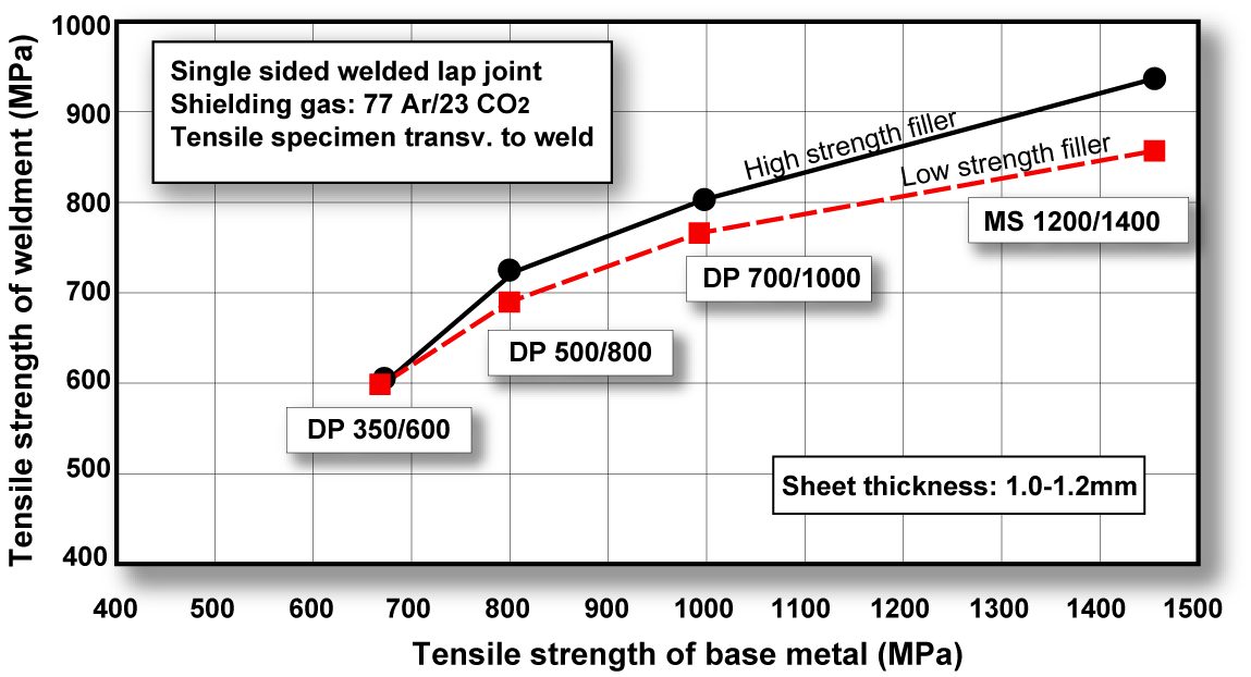
Figure 11: Influence of filler metal strength in arc welding of DP and mild steels. (Tensile strength is 560 MPa for low strength and 890 MPa for high-strength fillers. Fracture position in HAZ for all cases except DP 700/1000 and MS 1200/1400 combination with low-strength filler where fracture occurred in weld metal. Tensile strength equals peak load divided by cross-sectional area of sample.C-3)
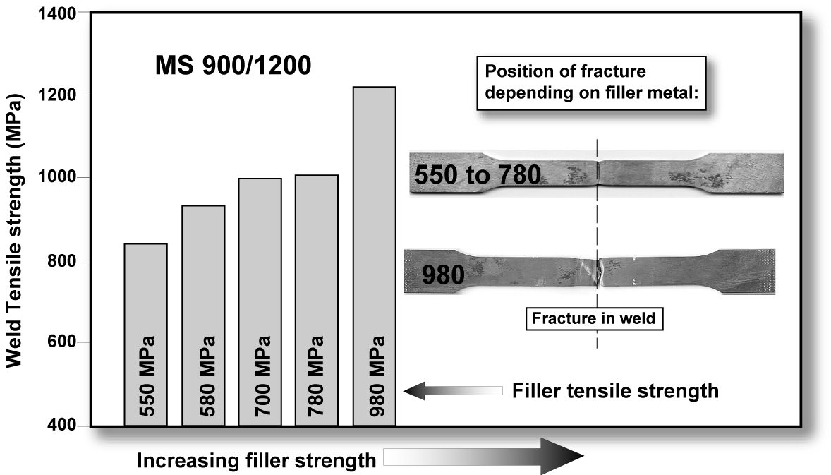
Figure 12: Influence of filler metal strength in GMAW (butt) welding on weld strength for MS steel. (Filler metal tensile strength range is 510-950 MPa.B-1)
Arc welds are normally used in local areas of vehicles where the loads are high. As required with all GMAW of any grade of steel, care should be taken to control heat input and the resulting weld metallurgy. The length of the GMA welds is often quite short. The reduction in strength for some of the AHSS GMA welds, in comparison to BM, can be compensated by increasing the length of the weld.
By adjusting the number and length (that is the total joined area) of welds, the fatigue strength of the joint can be improved. The fatigue strength of an arc-welded joint, in general, tends to be better than that of a spot-welded joint (Figure 13).
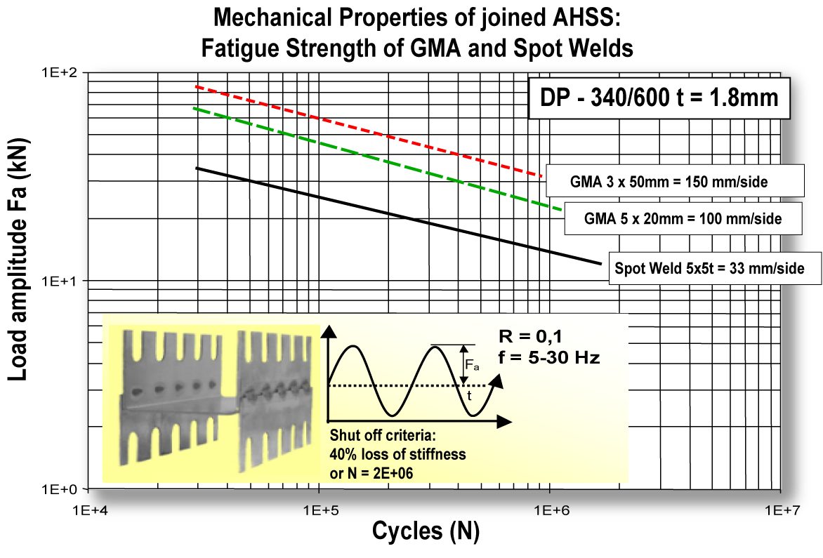
Figure 13: Fatigue strength of GMA-welded DP 340/600 compared to spot welding.L-2
Back To Top
Solid State Welding
Magnetic Pulse Welding (MPW) is a solid-state process that uses electromagnetic pressure to accelerate one workpiece to produce an impact against another workpiece. The metallic bond created by this process is similar to the bond created by explosion welding. MPW, also known as electromagnetic pulse or magnetic impact welding, is highly regarded for the capability of joining dissimilar materials.
Physics of the Process
Electromagnetic metal processing was developed in the late 1800s, and in succeeding years most applications for this technology were in metal forming. It was not recognized as a viable welding process, but a substantial renewal of interest has occurred recently in the further development of this technology for welding.
Fundamentally, both metal forming and welding use the same underlying physics. The process is driven by the primary circuit. A significant amount of energy, usually between 5 and 200 kJ, (1,124- and 44,962-lb force) is stored in capacitors charged to a high voltage that may range between 3,000 and 30,000 V. The capacitors are then discharged through low-inductance and highly conductive bus bars into a coil, or actuator. The resulting current takes the form of a damped sine wave, characterized as a ringing inductance-resistance-capacitance circuit. Peak currents during this process range between tens of thousands and millions of Amperes (A), with pulse widths on the order of tens of microseconds. This creates an extremely intense transient magnetic field in the vicinity of the coil. The magnetic field induces eddy currents in any conductive materials nearby, in the opposite direction to the primary current. The opposing fields in the coil and workpiece result in a high repulsion force. This force drives the flyer, or driver, workpiece (the workpiece closest to the driving coil) at high velocity toward the target, the stationary workpiece, resulting in a high impact between the two metals.
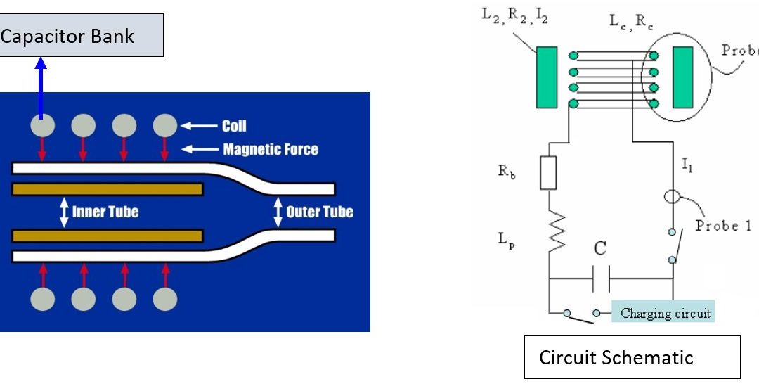
The impact pressure drives away the surface contaminants and provides for the intimate contact of clean surfaces across the weld interface. Metallic bonding results from this contact. A schematic of the process is shown in Figure 1 and in the video which follows.
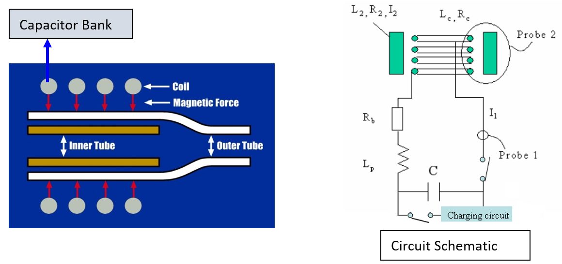
Figure 1: Basic diagram of the MPW process.
The following three elements are fundamental to achieving good magnetic pulse-welded joints:
- Correct welding machine parameters.
- Consideration of metal or material properties.
- Relative positioning of the flyer and the target workpieces.
Welding machine parameters determine the frequency and magnitude of the current waveform. High frequencies typically are favored for MPW. If the frequency is too low, the buildup of eddy currents in the flier workpiece will not be sufficient to achieve the velocities necessary for impact joining. The frequency is directly related to the electrical characteristics (LRC) of the circuit, including the capacitors and coil. Low system capacitances and inductances favor HF characteristics.
The properties of the workpiece metal, particularly of the flier, also contribute to determining the weldability of a given metal. Properties to be considered include electrical conductivity and strength. Metals with high electrical conductivity and low strength are most easily welded with the magnetic pulse process. Higher electrical conductivity facilitates greater induced currents in the flier workpiece, with correspondingly greater magnetic pressures. Lower YS facilitate displacements of the flier at lower magnetic pressures and are easier to accelerate to the required speed for welding. Carbon steel also can be welded when adjustments are made to the system power and frequency. Metals with relatively low electrical conductivity, such as austenitic stainless steels, are almost impossible to directly weld with the magnetic pulse process. They are readily welded, however, with the use of a driver plate. The driver plate is essentially a band of conductive material (typically Cu) wrapped around the low-conductivity flier. During welding, the driver reacts with the coil, pushing the actual flier to the necessary velocities for metallic bonding.A-11
Power Source
The essential component of an MPW system is a capacitor bank. The energy stored in the system can be determined from the size (capacitance) of the bank and the charge voltage using the following equation:

where:
E = Energy
C = Capacitance
V = Voltage
The energy is provided to the capacitors by a dedicated charging system. The capacity of the charging system largely controls the time required to charge the bank between subsequent welds. The charging circuit generally is actively cooled, allowing repeated use during production applications.
As previously mentioned, energy is transferred from the capacitors to the coil with an assembly of bus bars. Two considerations are key in the design of the bus bar assembly: it must have low inductance (in general, the majority of the system inductance should be at the coil), and low resistance contacts. When in use, the capacitors are charged relatively slowly to a predefined voltage. Once this voltage is reached, a fast-action switch is used to allow current flow to the coil. Switching typically is done using solid-state Silicon-Controlled Rectifiers (SCRs).A-11
Tubular Structures
MPW has great potential for joining tubular structures for automotive and aerospace applications and for fluid-carrying tubes. Examples of MPW tubular applications are shown in Figure 2. The process has several advantages that can significantly reduce manufacturing costs, summarized as follows:
1. HS joints can be produced that are stronger than the BM.
2. Leak-tight welds can be made.
3. High welding speeds, in the millisecond range make the process readily adapted to automation.
4. Dissimilar metals and difficult-to-weld materials, such as 303 stainless steel, can be joined.
5. Cold processing enables immediate handling.
6. Welds are made with no HAZ and minimum distortion.
7. Post-cleaning operations and Post Weld Heat Treatments (PWHT) are unnecessary.
8. The process is cost efficient because no filler metals or shielding gases are needed, and environmental costs are reduced.

Figure 2: Examples of MPW tubular applications.
Applications
MPW has been successfully applied to various similar and dissimilar metal combinations. Materials with high conductivity, such as Al and Cu, are the easiest to weld with the magnetic pulse process. Al has been successfully welded to steel and stainless steel. Cu has been successfully welded to steel and stainless steel.
MPW has been used to join fuel pipes, fuel filters, exhaust system components, power cables, and for the construction of automotive body parts. The development of new applications of the MPW process continues, with the goal of advancing these applications to mass production. The process is achieving increased recognition for applications across the industrial spectrum.A-11
Safe Practices
The potential hazards of MPW include mechanical and electrical risks, noise, flash, and fumes.
Mechanical
The welding machine should be equipped with appropriate safety devices to prevent injury to the operator’s hands or other parts of the body. Initiating devices, such as push buttons or foot switches, should be arranged and guarded to prevent inadvertent actuation.
Machine guards, fixtures, and operating controls must prevent the operator from coming in contact with the coil and workpiece and must block or deflect the weld jet associated with the process.
Electrical
All doors and access panels on machines and controls must be kept locked or interlocked to prevent access by unauthorized personnel. The interlocks should interrupt the power and discharge all the capacitors through a suitable resistive load when the panel door is open.
Personal Protection
Appropriate guards should be in place to isolate the operator from the process. Operating personnel should wear ear protection when the welding operations produce high noise levels.
Additional information on safe practices for welding is provided in the latest edition of ANSI Safety in Welding, Cutting, and Allied Processes, Z49.1 published by AWS.
Back To Top

