Coating-related Defect Avoidance

Coating-related Defect Avoidance

This article focuses on the role of Zinc coatings in causing so-called blowhole defects during gas metal arc welding of automotive body-in-white panels. Blowholes occur when vaporized coating material becomes trapped in the molten weld pool during solidification. This is more prevalent in overlap or T-joint configurations compared to butt joints, where vapors can escape more easily. Random variations can lead to differing pore rates in welded joints, necessitating a statistical approach to evaluation.

Experimental Plan and Methodology

An experimental plan, evaluating the factors contributing to blowhole formation, including heat input, filler wire type, gap distance, and welding conditions was used. Over 1,000 welds were performed to gather sufficient data for statistical analysis. The methodology focused on measuring pore rates and the length of defects through x-ray testing.

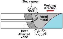
Figure 1: Blowholes are formed by vaporized Zinc escaping through the molten zone.

Solutions

  • Introduction of Gaps: A gap greater than 0.3 mm between sheets facilitates vapor extraction during welding, significantly reducing blowhole formation. Controlling the gap between sheets is challenging and costly in automotive assemblies. It may be an adequate solution, when the overlap width cannot be adjusted.

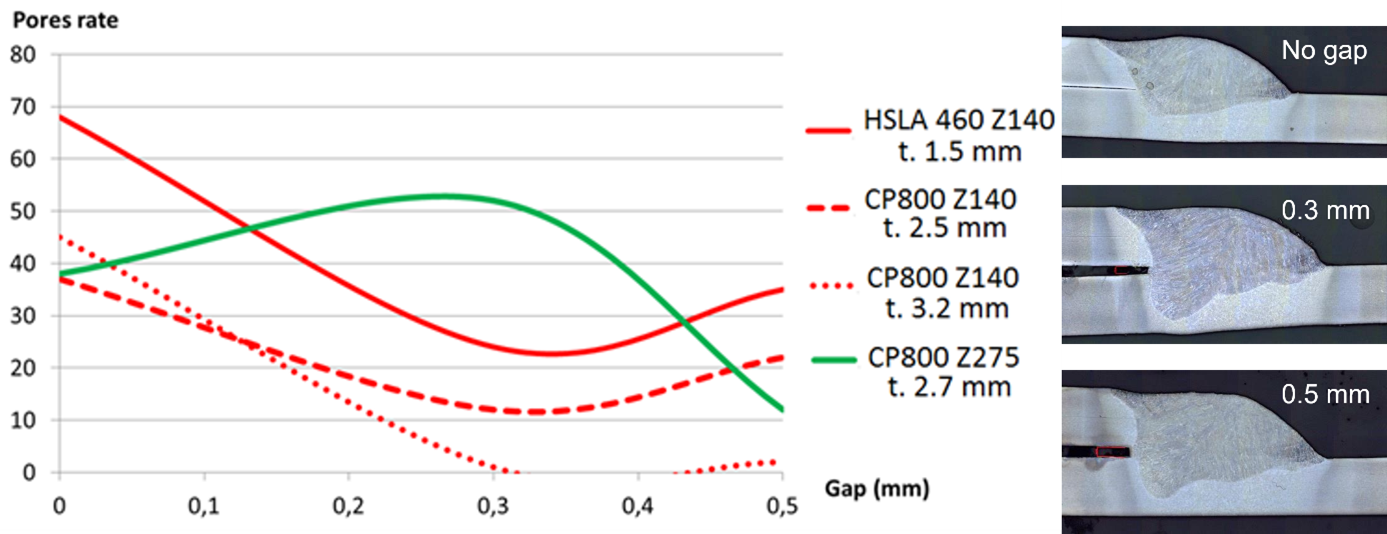
Figure 2: Pore rate in percent for different gap widths and steels (left) and cross-sections with increasing gaps (right). For normal coating level Z140, increasing the gap decreased pore and blowhole formation. Using a steel with significantly increased coating did not show this effect.

  • Reduction of Overlap Width: Decreasing the overlap width not only helps vapors escape more easily but also reduces the overall weight of the assembly, making it the preferable solution

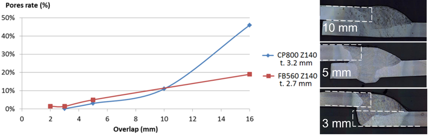
Figure 3: Pore rate in percent for increasing overlaps (left) and cross-sections with increasing overlap (right). Decreasing the overlap decreased pore and blowhole formation.

Effects on Mechanical Properties

Neither the gap nor overlap width significantly affected ultimate tensile strength (UTS) or fatigue performance, if the gap remained below 1 mm. The presence of blowholes did not adversely affect fatigue performance, although they could lead to reduced static strength of the joint if located at critical points within the load path.

Key Messages

  • MAG welding of zinc-coated steels can lead to blowholes.
  • Utilizing pulsed current may help minimize these defects, but welding parameters have limited effects on blowhole occurrence.
  • Introducing a gap or reducing overlap width are effective strategies to mitigate these issues, with no impact on mechanical properties.

Source

J. Haouas, Solutions for improvement of zinc coated steels arc welding, ICWAM conference 2017, Metz

Role of Coatings in the Formation of Defects in AHSS Welds

Role of Coatings in the Formation of Defects in AHSS Welds

A common issue when welding Advanced High-Strength Steels (AHSS) is with protective coatings causing weld defects. A group of researchers at the NMAM Institute of Technology and Dong-Eui University studied common issues with gas metal arc welding (GMAW) in the cold metal transfer (CMT) mode on a zinc-coated steel.V-2  The study used infrared thermography to observe the welds as they were created, helping to get detailed observations on some defects appearing in real time. With GMAW in CMT mode, the prevailing defect with welding a zinc-coated steel was porosity from metal vapors escaping through the weld. This issue could be addressed by adjusting the heat input and travel speed to provide more time for metal gases to escape.

In Figure 1, it shows that with a higher heat input, more heat is in the weld puddle. In low and medium heat inputs, the puddle is above melting temperature, but not as high as the high heat input. Figure 2 shows that the low heat input also has the fastest solidification rate, and the high heat input has the slowest solidification rate. Figure 3 shows where the zinc vapors from the molten coating evaporate through the weld. In the left picture, at low heat input, the nucleation is contained inside of the weld, and the fusion zone would collect in the fusion zone. In the middle picture, at medium heat input, the zinc vapors bubble out just as the metal starts to solidify. In the right picture, at high heat input, the zinc bubbles out in the weld puddle while it is still molten.

Figure 1: Infrared Thermography of Weld Bead.V-2

Figure 1: Infrared Thermography of Weld Bead.V-2


Figure 2: Variation of temperature during CMT for High, Medium, and Low Heat Input.V-2

Figure 2: Variation of temperature during CMT for High, Medium, and Low Heat Input.V-2


Figure 3: Variation of Zinc Porosity Position vs Low, Medium, and High Heat Input.V-2

Figure 3: Variation of Zinc Porosity Position vs Low, Medium, and High Heat Input.V-2


These factors combined indicate several factors that influence zinc porosity in GMAW CMT weldments. The researchers concluded that at low heat inputs, the zinc collects in the fusion zone. At medium heat inputs, the solidification rate and temperature gradient through the weld puddle traps the zinc in the fusion zone but also allows some to bubble out through the weld puddle. This caused the worst material properties of the three weldments for the researchers. At high heat inputs, the zinc bubbles out through the weld puddle, before solidification occurs. This condition is optimal, to reduce porosity with zinc metal vapors, the heat input should be increased so that the weldment temperature increases and solidification rate decreases.