Arc Welding, Joining
Quenching and partitioning (QP) steels are one of several third generation advanced high strength steel formed by controlled martensite phase fractions and retained austenite. Researchers from the University of Shanghai Jiao Tong tested the effect of HAZ softening in a QP1180 lap joint with the GMAW cold metal transfer (CMT) process.W-1 The steel was welded with ER130s electrode. The fusion zone consisted of chiefly acicular ferrite. The supercritical zone consists of martensite, which is harder than the base metal. There is a drop in hardness (100 HV) in the subcritical zone, and there is a noted lack of retained austenite present in the microstructure. Precipitates are also present in the subcritical zone. The intercritical HAZ only experiences mild softening; where fresh martensite has formed. The softening in the subcritical HAZ presents room for failure that must be accounted for when planning welding using CMT.
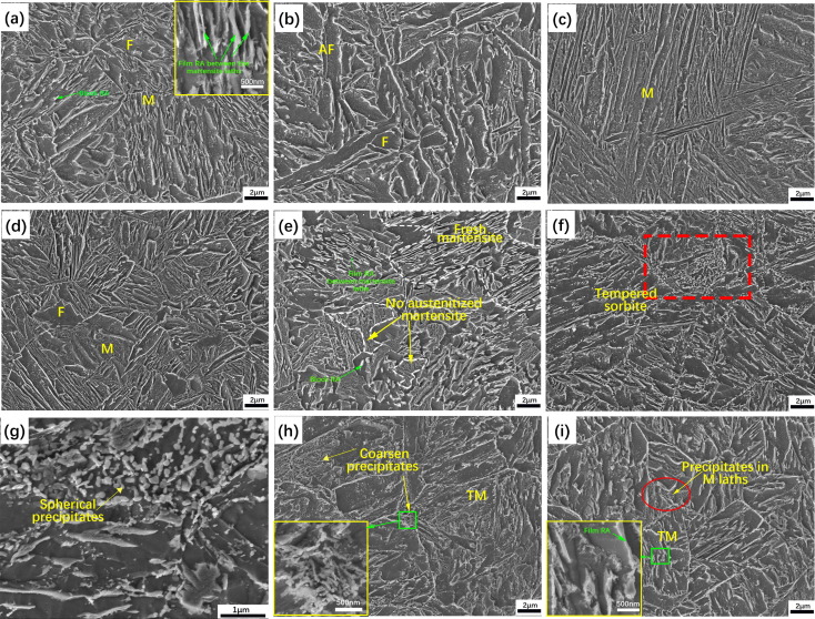
Figure 1 shows the different microstructures in detail throughout the weld and the base metal. In the softening zone shown in Figure 2 correlates to the tempered sorbite region in Figure 1 (part f). The hardness maps shows that the fusion zone is approximately as hard as the base metal, with the supercritical HAZ having the highest hardness values before rapidly softening in the intercritical and subcritical HAZ zones. The softened region must be accounted for in designing CMT or other high heat input welded components.
Figure 1: a) Base metal with retained austenite between martensite lathes, b) fusion zone with acicular ferrite and ferrite, c) coarse martensite grains in supercritical HAZ, d) fine martensite grains and ferrite in supercritical HAZ, e) intercritical HAZ with fresh martensite and untransformed martensite, f) softest region in subcritical HAZ; shows tempered sorbite, g)zoomed in region of subcritical zone with precipitates, h) subcritical HAZ with 350-360HV hardness, i) hardness with 380-390HV.W-1
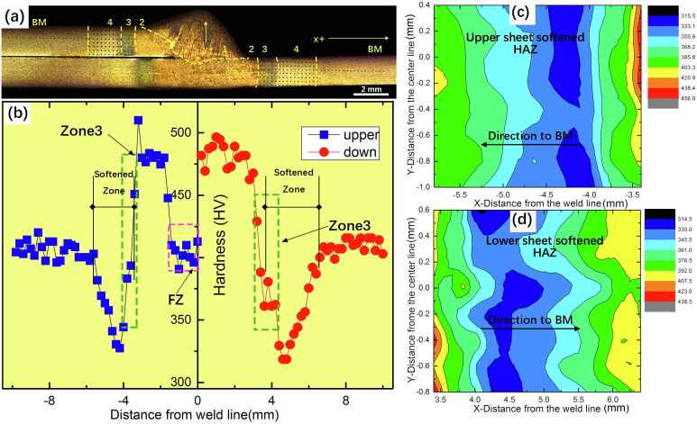
Figure 2: a) macrostructure of the CMT-welded QP1180 joint, b) hardness chart through joint, c) hardness map in upper sheet, d) hardness map in lower sheet. 1) fusion zone, 2) supercritical HAZ, 3) intercritical HAZ, 4) subcritical HAZ, BM = base metal.W-1

Arc Welding
This article summarizes a paper by W. Mohr and N. Kapustka, EWI, entitled, “Fatigue of GMAW-P Lap Joints in Advanced High-Strength Steels.”M-13
EWI has performed fatigue tests on welds from four Advanced High-Strength Steels (AHSS) in the uncoated condition. The materials were provided in three thicknesses as follows, 2.0-mm DP 780, 1.8-mm 590 SF, 2.0-mm DP 980, and 2.8-mm CP 800. Referring to Figure 1(a), welding parameters were selected to meet the weld profile requirements listed below:
The travel speed to achieve such combinations was 23 mm/s for three of the sheets and 13 mm/s for the 2.8-mm-thick CP 800. Figure 1 shows a completed panel.
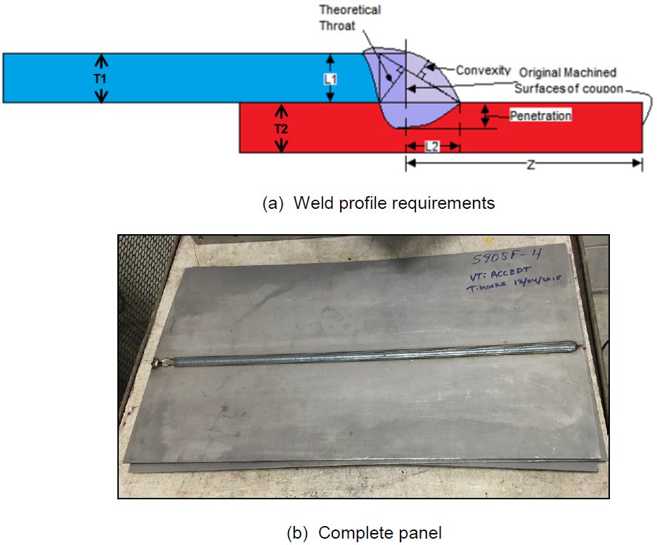
Figure 1: Completed Panel.M-13
Specimens were cut from the lap-welded panels in a configuration recommended by Z 2275, with minimum reduced sections of 20-mm wide, with 20-mm radii on both sides to a full width of 30 mm, as shown in Figure 2.
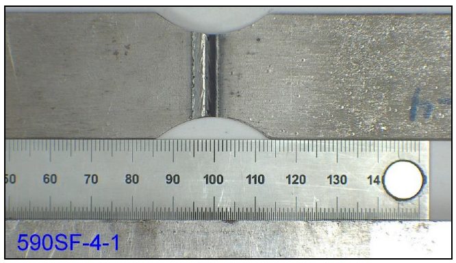
Figure 2: Specimen Design.M-13
Fixtures for the bend testing had eight, 6.3-mm radius rollers, four on top and four on the bottom, with offsets of the roller centers to accommodate the lap-joint configuration and the differing sheet thicknesses. The interior span was 120 mm, while the exterior span was 210 mm. The full bending fixture, with a specimen inserted, is shown in Figure 3.
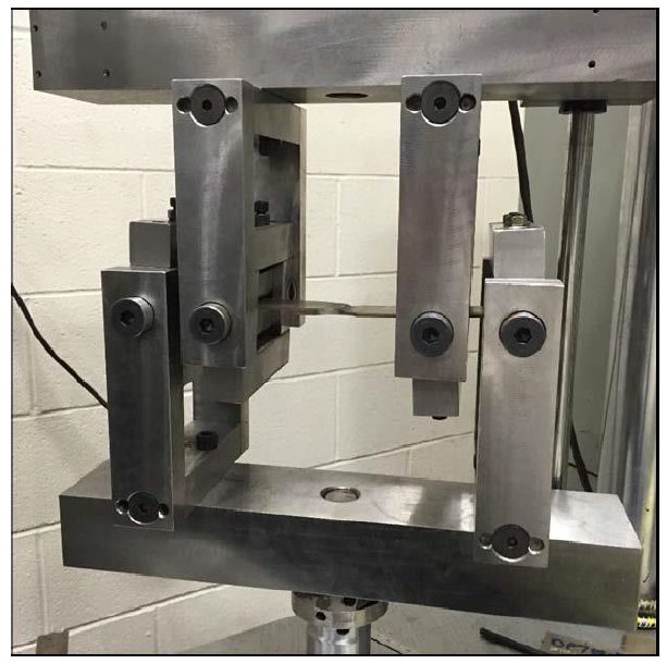
Figure 3: Bending Test Fixture.M-13
Weld profiles were achieved that met the weld profile requirements for each sheet material type. These weld profiles are shown for the four sheet materials in Figure 4. Fatigue testing results in tension at R = 0.3 gave lifetimes between 30,000 and 9 million cycles, with run-outs at 10 million cycles, as shown in Figure 5.
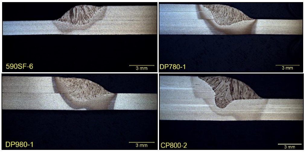
Figure 4: Cross Sections of Lap Joints (etched with 2% Nital).M-13
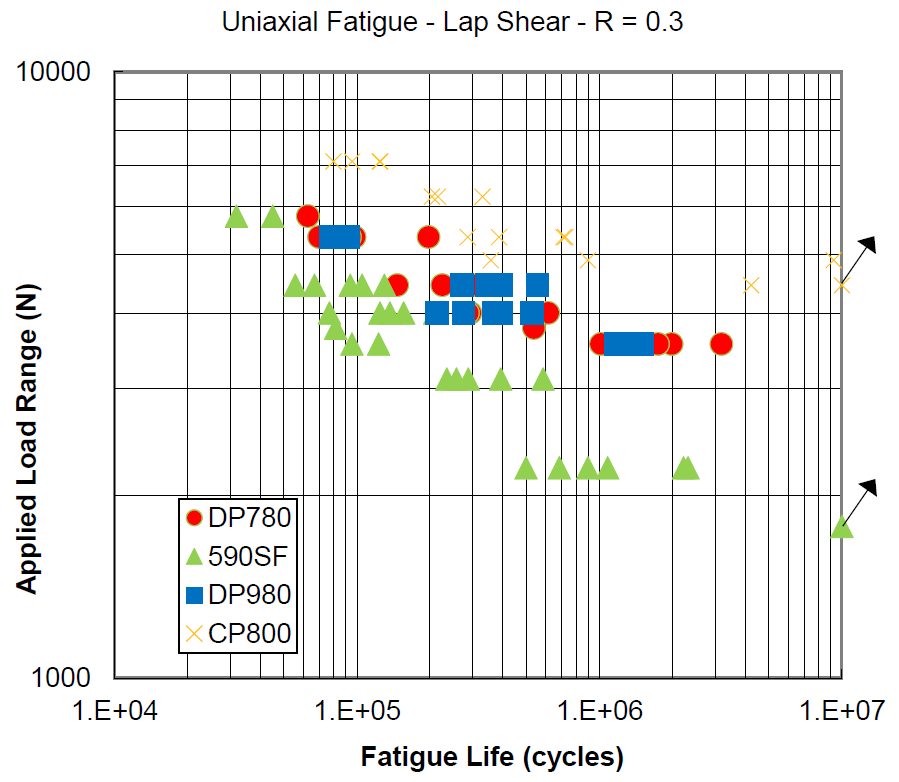
Figure 5: Results of Fatigue Testing in Tension at R= 0.3.M-13
Weld root cracking dominated in the 590 SF, as well as the DP 780 and DP 980, with an example shown in Figure 6. Weld toe cracking was observed on the 2.8-mm-thick CP 800, with an example shown in Figure 7.
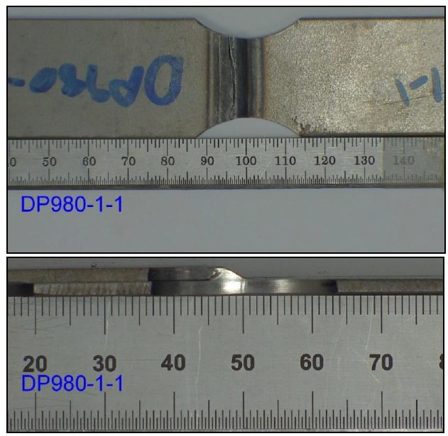
Figure 6: Example for a Root Crack Breaking Through the Weld Metal on DP 980.M-13
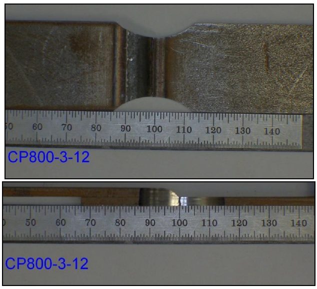
Figure 7: Example of a Toe Crack Breaking Through the Base Metal.M-13
Fatigue testing in bending at R = -1 gave lifetimes between 30,000 and 2 million cycles, with run-outs on tests that continued to up to 7 million cycles, as shown in Figure 8.
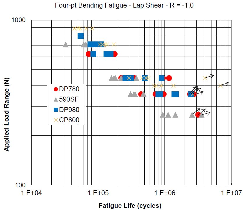
Figure 8: Four-Point Bending Tests at R = -1.M-13
Taking the differing thicknesses, minor variations in minimum width, and the stress concentrations from the radii into account, the concentrated stress range was calculated to compare the four materials on a common basis, as shown in Figure 9.
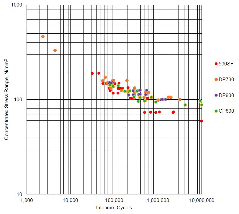
Figure 9: Concentrated Stress Range versus Lifetime for Tension Tests.M-13
The fatigue cracks initiated at the root for the 1.8-mm 590 SF on both tension and bending testing. The fatigue cracks initiated at the weld toe for the 2.8-mm CP 800 on both tension and bending testing. The fatigue cracks initiated from the weld root in the tension testing and from primarily the weld cap in bending testing, for the 2.0-mm-thick DP 780 and 2.0-mm-thick DP 980.
High Energy Density Welding
Butt Welds and Tailor-Welded Products
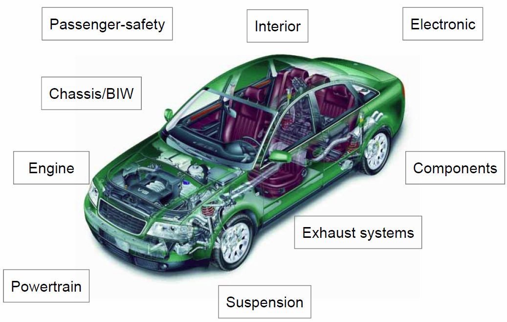
Figure 1: Common automotive applications using laser welding.T-9
AHSS grades can be laser butt-welded and are used in production of tailored products (tailor-welded blanks and tubes). The requirements for edge preparation of AHSS are similar to mild steels. In both cases, a good quality edge and a good fit-up are critical to achieve good-quality welds. The blanking of AHSS needs higher shear loads than mild steel sheets. (see Culling in Blanking, Shearing and Trim Operations)
If a tailored product is intended for use in a forming operation, a general stretchability test such as the Erichsen (Olsen) cup test can be used for assessment of the formability of the laser weld. AHSS with tensile strengths up to 800 MPa show good Erichsen test values (Figure 2). The percent stretchability in the Erichsen test = 100 × the ratio of stretchability of weld to stretchability of BM.
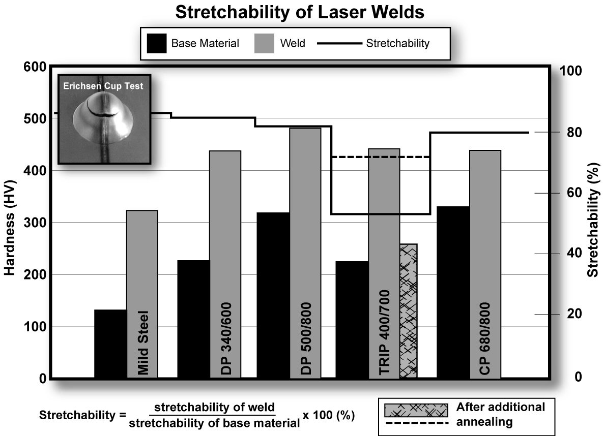
Figure 2: Hardness and stretchability of laser butt welds with two AHSS sheets of the same thickness (Erichsen test values describe the stretchability.B-1)
The hardness of the laser welds for AHSS is higher than for mild steels (Figure 3). However, good stretchability ratios in the Erichsen test can be achieved when the difference in hardness between weld metal and BM is only slightly higher for AHSS compared to mild steels. If the hardness of the weld is too high, a post-annealing treatment (using HF-equipment or a second laser scan) may be used to reduce the hardness and improve the stretchability of the weld.
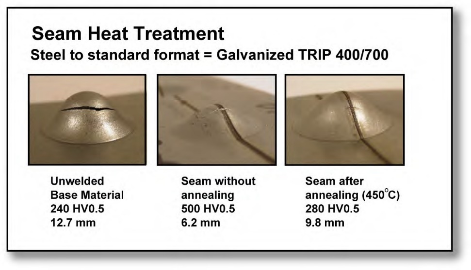
Figure 3: Improved stretchability of AHSS laser welds with an induction heating post-Heat treatment (Testing performed with Erichsen cup test.T-3)
Laser butt-welded AHSS of very high strength (for example Martensite steels) have higher strength than GMAW [LINK TO 3.2.1] welded joints. The reason is that the high CR in the laser welding process prompts the formation of hard martensite and the lower heat input reduces the soft zone of the HAZ.
Laser butt-welding is also used for welding tubes in roll-forming production lines as an alternative method for HF induction welding.
Assembly Laser Welding
Automotive applications use a variety of welding joint designs for laser welding in both lap joint and seam butt joint configurations as shown in Figure 4. Lap joints and seam butt joint configurations use different characteristics. Seam welds on butt joints need less power from the machine than lap joints due to the smaller weld fusion area, producing less distortion and a smaller HAZ. Butt joint configurations are more cost efficient. However, the fit up for seam welds can be more difficult to obtain than those of lap joints. Also, lap joints tend to provide a larger process window.
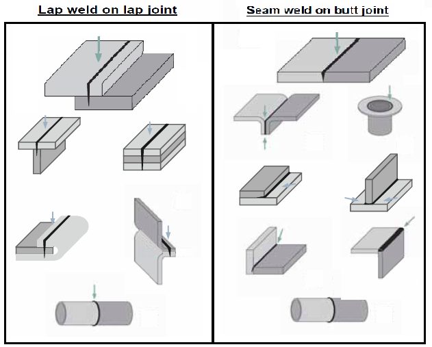
Figure 4: Common seam and joint types for laser welding of automotive applications.T-9
When seam welding butt joint configurations, a general guideline for fit-up requirements include a gap of 3-10% the thickness of the thinnest sheet being welding and an offset of 5-12% thickness of the thinnest sheet. A guideline for lap joints can require a gap of 5-10% the thickness of the top sheet being welded (Figure 5). These general guidelines are not absolute values due to the change of variables such as the focus spot size, the edge geometry for butt welds, strength requirements, etc.
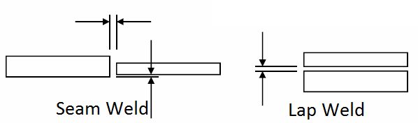
Figure 5: Fit-up requirements for butt joint and lap joint configurations in laser welding.T-9
Laser welding is often used for AHSS overlap joints. This type of weld is either a conventional weld with approximately 50% penetration in the bottom sheet or an edge weld. Welding is performed in the same way as for mild steels, but the clamping forces needed for a good joint fit-up are often higher with AHSS than for mild steels. To achieve good laser-welded overlap joints for Zn-coated AHSS, a small intermittent gap (0.1-0.2 mm) between the sheets is recommended, which is identical to Zn-coated mild steels. In this way, the Zn does not get trapped in the melt, avoiding pores and other imperfections. An excessive gap can create an undesirable underfill on the topside of the weld. Some solutions for lap joint laser welding Zn- coated material are shown in Figure 6.
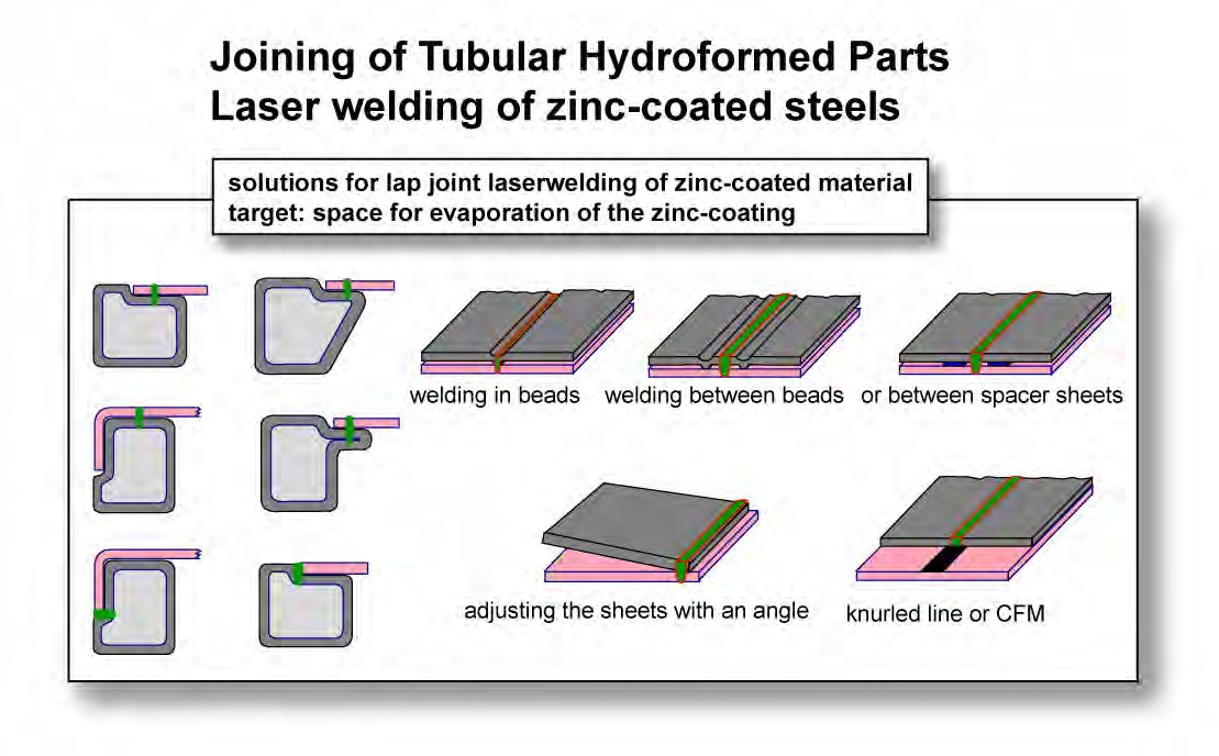
Figure 6: Laser welding of Zn-coated steels to tubular hydroformed parts.L-3
StudiesL-59 have shown welding Zn-coated steels can be done without using a gap between the overlapped sheets. This is accomplished using dual laser beams. While the first beam is used to heat and evaporate the Zn coating, the second beam performs the welding. The dual laser beam configuration combines two laser-focusing heads using custom-designed fixtures.
Remote Laser Welding
Remote scanner welding is used for many automotive applications, including seating (recliners, frames, tracks, and panels), BIW (trunks, rear panels, doors I hang on parts, side walls, and pillars) and interior (IP beams, rear shelfIhat rack) (Figure 7). Compared to conventional laser welding, remote scanner welding has several advantages. Those include a reduced cycle time (via reduction of index time), programmable weld shapes (ability to customize weld shape to optimize component strength), large stand-off (longer protection glass life), and reduced number of clamping fixtures (via reduced number of stations).
Remote laser welding, or “welding on the fly”, combines a robot and scanner optics to position the focused laser beam on the workpiece on the fly. The robot arm guides the scanner optics along a smooth path about half a meter over the workpiece. Extremely nimble scanning mirrors direct the focal point in fractions of a second from weld seam to weld seam. A fiber-delivered, solid-state laser is the source of the joining power far away from the processing station. The scanning optic or Programmable Focusing Optic (PFO) at the end of the laser’s fiber-optic cable is the central element for precise positioning of the laser’s focus point on the component to be welded. Inside the PFO, two scanner mirrors direct the beam through a “flat field” optic, which focuses the beam onto a common focus plane no matter where it is in the work envelope of the PFO. The PFO is also equipped with a motorized lens that allows the focus plane to be moved up and down in the Z-axis. The repositioning of the focused laser beam from one end of the entire work envelope to the other takes about 30 ms.T-9
Figure 7: Remote laser welding of automotive applications.T-9
There are three basic preconditions for welding on the fly. First, a solid-state laser is needed as the beam source. Solid-state lasers enable delivery of the laser beam through a highly flexible fiber optic cable, which is required when joining components in 3D space with a multi-axis robot. Second, a laser with excellent beam quality and the appropriate power is required. Beam quality is the measure of focus-ability of a laser, and the long focal lengths required for remote welding necessitate superior beam quality (i.e., 4 to 8 mm-mrad) to achieve the appropriate focused spot size (i.e., about 0.6 mm) at the workpiece. For remote welding in automotive body production, typically about 4 to 6 kW of laser power is used. The third essential precondition is precise positioning of the weld seams, which requires axis synchronization between the robot and the scanner control. This allows the weld shape programmed in the scanner control for a specific shape weld to have proper shape with the robot moving at various speeds over the part to be welded. Some control architectures use “time” synchronization. The problem here is that if the robot speed is changed for any reason, the weld shape will also change because the axes are not synchronized.T-9
Body-in-White (BIW) Joining
Laser-based solutions can offer a high- and cost-effective improvement potential for steel-based BIW joining. The laser joining design’s stiffness increases in direct relation to the laser weld length. Also, at low process time, there is up to a +14% torsional stiffness increase without any additional joining technique, shown in Table 1.
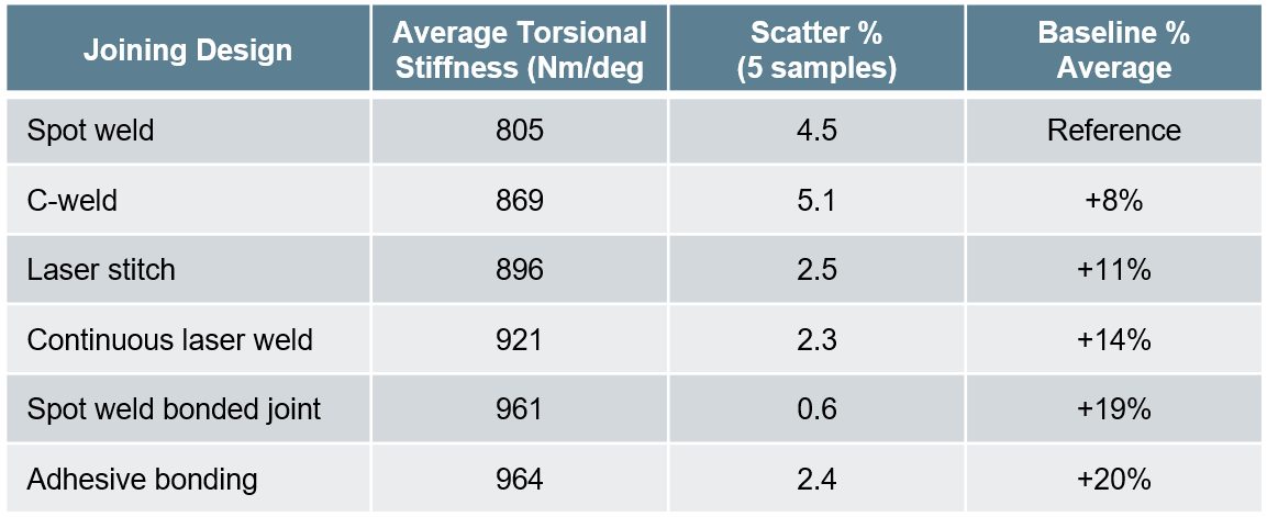
Table 1: Stiffness performances comparison for several joining designs.A-16
Laser weld shape optimization can help to homogenize performances and increasing the laser weld shape factor leads to a signification reduction of IF fracture risk (Figure 8).
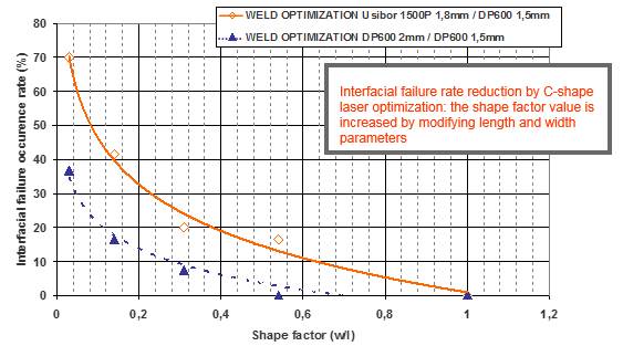
Figure 8: Impact of laser weld design optimization on fracture type.A-16
DP 800 (with additional retained austenite and associated bainite) has the advantage of weight reduction and equally good properties when laser welding as the DP 800. The absolute strength of DP 800 is slightly higher, but the ductility for the DP 800 is greater, shown in Figure 9.
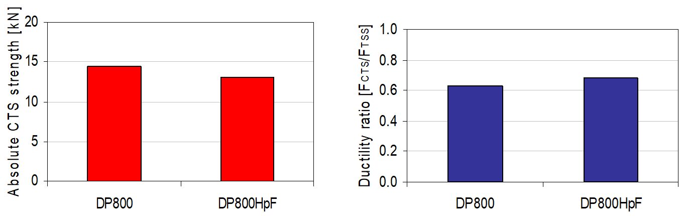
Figure 9: Absolute strength and ductility of DP 800 and DP 800.T-10
Figure 10 shows a cross-tension test in which both materials fail outside the weld zone, DP 800 failing entirely in the HAZ and DP 800 failing partly in the HAZ and partly in the BM.
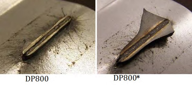
Figure 10: Cross-tension testing of DP 800 and DP 800.T-10
Figure 11 is the microhardness profile of 1.6-mm Q&P 980’s laser weld joint. Microhardness of both welded seam and HAZ are all higher than BM, and there is no obvious softened zone in HAZ.
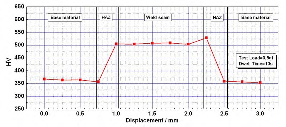
Figure 11: Microhardness profile of 1.6-mm Q&P 980’s laser weld joint.B-4
Figure 12 is Erichsen test result for the BM and weld seam of 1.6-mm Q&P 980, showing good stretchability.
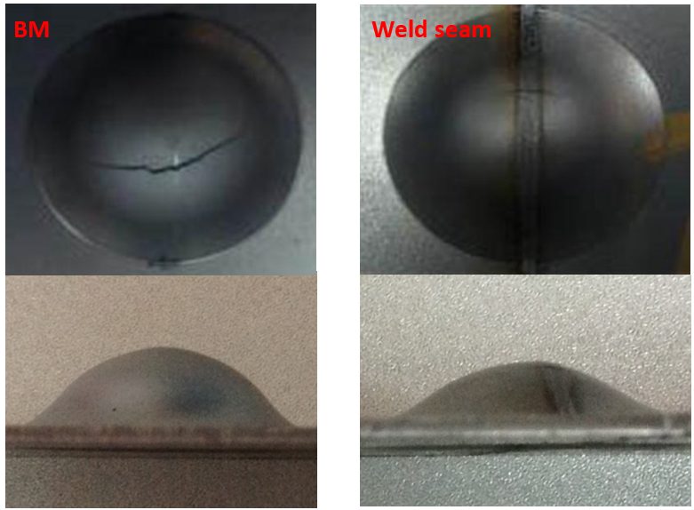
Figure 12: Erichsen test result of 1.6-mm Q&P 980, laser welded.B-4
Hybrid Laser and GMAW Welding
In hybrid welding process parameters such as stick out and torch angle are very important to decide overall joint performance. A model has been developed to predict the penetration and toe length under similar heat input conditions, shown in Figure 13. The gap, stickout and angle shows synergic agreement with penetration and toe length but the interactions among them can show disagreement.
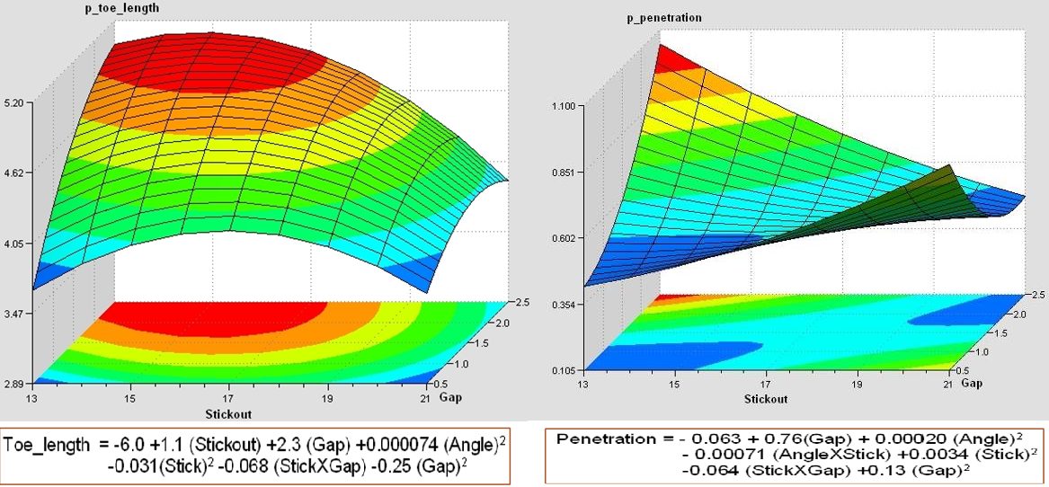
Figure 13: Effects of toe length and penetration.T-10
The weld joint strength increases with the increase in wire feed rate for a given laser power shown in Figure 14.
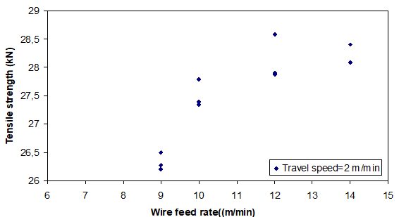
Figure 14: Wire feed rate versus tensile strength of hybrid laser and MIG welds.T-10
Back To Top