The word “laser” is an acronym for “light amplification by stimulated emission of radiation.” Lasers produce a special form of light (electromagnetic energy) consisting of photons that are all of a single coherent wavelength. Light of this form can be focused to...
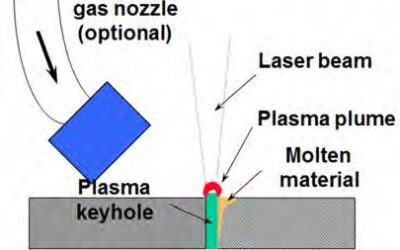
Laser Welding
read more