Simulation
Predicting metal flow and failure is the essence of sheet metal forming simulation. Characterizing the stress-strain response to metal flow requires a detailed understanding of when the sheet metal first starts to permanently deform (known as the yield criteria), how the metal strengthens with deformation (the hardening law), and the failure criteria (for example, the forming limit curve). Complicating matters is that each of these responses changes as three-dimensional metal flow occurs, and are functions of temperature and forming speed.
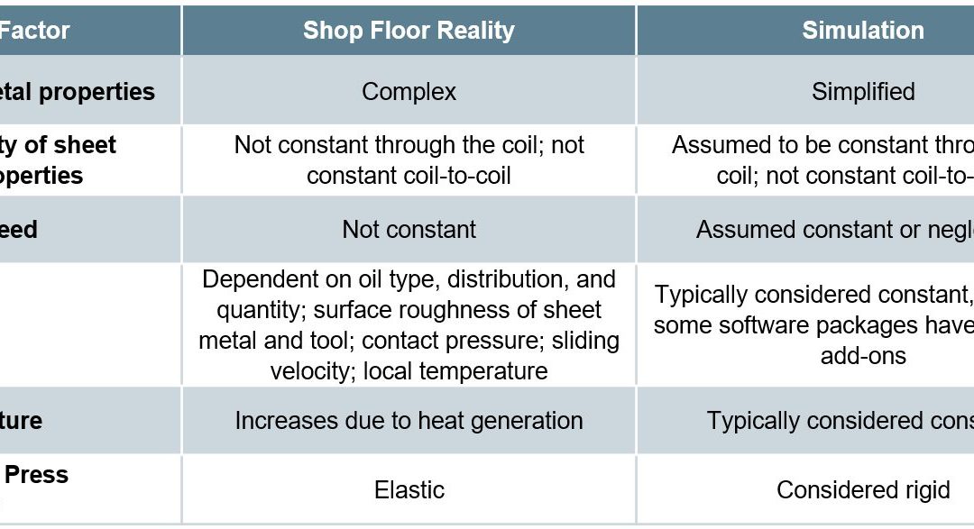
The ability to simulate these features reliably and accurately requires mathematical constitutive laws that are appropriate for the material and forming environments encountered. Advanced models typically improve prediction accuracy, at the cost of additional numerical computational time and the cost of experimental testing to determine the material constants. Minimizing these costs requires compromises, with some of these indicated in Table I created based on Citations B-16 and R-28.
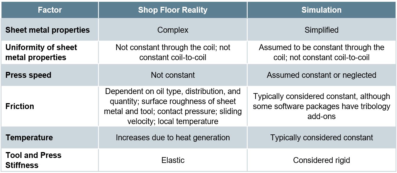
Table I: Deviations from reality made to reduce simulation costs. Based on Citations B-16 and R-28.
Yield Criteria
The yield criteria (also known as the yield surface or yield loci) defines the conditions representing the transition from elastic to plastic deformation. Assuming uniform metal properties in all directions allows for the use of isotropic yield functions like von Mises or Tresca. A more realistic approach considers anisotropic metal flow behavior, requiring the use of more complex yield functions like those associated with Hill, Barlat, Banabic, or Vegter.
No one yield function is best suited to characterize all metals. Some yield functions have many required inputs. For example, “Barlat 2004-18p” has 18 separate parameters leading to improved modeling accuracy – but only when inserting the correct values. Using generic textbook values is easier, but negates the value of the chosen model. However, determining these variables typically is costly and time-consuming, and requires the use of specialized test equipment.
Hardening Curve
Metals get stronger as they deform, which leads to the term work hardening. The flow stress at any given amount of plastic strain combines the yield strength and the strengthening from work hardening. In its simplest form, the stress-strain curve from a uniaxial tensile test shows the work hardening of the chosen sheet metal. This approach ignores many of the realities occurring during forming of engineered parts, including bi-directional deformation.
Among the simpler descriptions of flow stress are those from Hollomon, Swift, and Ludvik. More complex hardening laws are associated with Voce and Hockett-Sherby.
The strain path followed by the sheet metal influences the hardening. Approaches taken in the Yoshida-Uemori (YU) and the Homogeneous Anisotropic Hardening (HAH) models extend these hardening laws to account for Bauschinger Effect deformations (the bending-unbending associated with travel over beads, radii, and draw walls).
As with the yield criteria, accuracy improves when accounting for three-dimensional metal flow, temperature, and forming speed, and using experimentally determined input parameters for the metal in question rather than generic textbook values.
Failure Conditions
Defining the failure conditions is the other significant challenge in metal forming simulation. Conventional Forming Limit Curves describe necking failure under certain forming modes, and are easier to understand and apply than alternatives. Complexity and accuracy increase when accounting for non-linear strain paths using stress-based Forming Limit Curves. Necking failure is not the only type of failure mode encountered. Conventional FLCs cannot predict fracture on tight radii and cut edges, nor can they account for dimensional issues like springback. For these, failure criteria definitions which are more mathematically complex are appropriate.
Constitutive Laws and Their Influence
on Forming Simulation Accuracy
Many simulation packages allow for an easy selection of constitutive laws, typically through a drop-down menu listing all the built-in choices. This ease potentially translates into applying inappropriate selections unless the simulation analyst has a fundamental understanding of the options, the inputs, and the data generation procedures.
Some examples:
- The “Keeler Equation” for the estimation of FLC0 has many decades of evidence in being sufficiently accurate when applied to mild steels and conventional high strength steels. The simple inputs of n-value and thickness make this approach particularly attractive. However, there is ample evidence that using this approach with most advanced high strength steels cannot yield a satisfactory representation of the Forming Limit Curve.
- Even in cases where it is appropriate to use the Keeler Equation, a key input is the n-value or the strain hardening exponent. This value is calculated as the slope of the (natural logarithm of the true stress):(natural logarithm of the true strain curve). The strain range over which this calculation is made influences the generated n-value, which in turn impacts the calculated value for FLC0.
- The strain history as measured by the strain path at each location greatly influences the Forming Limit. However, this concept has not gained widespread understanding and use by simulation analysts.
- A common method to experimentally determine flow curves combines tensile testing results through uniform elongation with higher strain data obtained from biaxial bulge testing. Figure 1 shows a flow curve obtained in this manner for a bake hardenable steel with 220 MPa minimum yield strength. Shown in Figure 2 is a comparison of the stress-strain response from multiple hardening laws associated with this data, all generated from the same fitting strain range between yield and tensile strength. Data diverges after uniform elongation, leading to vastly different predictions. Note that the differences between models change depending on the metal grade and the input data, so it is not possible to say that one hardening law will always be more accurate than others.

Figure 1: Flow curves for a bake hardenable steel generated by combining tensile testing with bulge testing.L-20

Figure 2: The chosen hardening law leads to vastly different predictions of stress-strain responses.L-20
- Analysts often treat Poisson’s Ratio and the Elastic Modulus as constants. It is well known that the Bauschinger Effect leads to changes in the Elastic Modulus, and therefore impacts springback. However, there are also significant effects in both Poisson’s Ratio (Figure 3) and the Elastic Modulus (Figure 4) as a function of orientation relative to the rolling direction. Complicating matters is that this effect changes based on the selected metal grade.

Figure 3: Poisson’s Ratio as a Function of Orientation for Several Grades (Drawing Steel, DP 590, DP 980, DP 1180, and MS 1700) D-11

Figure 4: Modulus of Elasticity as a Function of Orientation for Several Grades (Drawing Steel, DP 590, DP 980, DP 1180, and MS 1700) D-11
Complete material card development requires results from many tests, each attempting to replicate one or more aspects of metal flow and failure. Certain models require data from only some of these tests, and no one model typically is best for all metals and forming conditions. Tests described below include:
- Tensile testing [room temperature at slow strain rates to elevated temperature with accelerated strain rates]
- Biaxial bulge testing
- Biaxial tensile testing
- Shear testing
- V-bending testing
- Tension-compression testing with cyclic loading
- Friction
Tensile testing is the easiest and most widely available mechanical property evaluation required to generate useful data for metal forming simulation. However, a tensile test provides a complete characterization of material flow only when the engineered part looks like a dogbone and all deformation resulted from pulling the sample in tension from the ends. That is obviously not realistic. Getting tensile test results in more than just the rolling direction helps, but generating those still involves pulling the sample in tension. Three-dimensional metal flow occurs, and the stress-strain response of the sheet metal changes accordingly.
The uniaxial tensile test generates a draw deformation strain state since the edges are free to contract. A plane strain tensile test requires using a modified sample geometry with an increased width and decreased gauge length,
Forming all steels involves a thermal component, either resulting from friction and deformation during “room temperature” forming or the intentional addition of heat such as used in press hardening. In either case, modeling the response to temperature requires data from tests occurring at the temperature of interest, at appropriate forming speeds. Thermo-mechanical simulators like Gleeble™ generate such data.
Conventional tensile testing occurs at deformation rates of 0.001/sec. Most production stamping occurs at 10,000x that amount, or 10/sec. Crash events can be 2 orders of magnitude faster, at about 1000/sec. The stress-strain response varies by both testing speed and grade. Therefore, accurate simulation models require data from higher-speed tensile testing. Typically, generating high speed tensile data involves drop towers or Split Hopkinson Pressure Bars.
A pure uniaxial stress state exists in a tensile test only until reaching uniform elongation and the beginning of necking. Extrapolating uniaxial tensile data beyond uniform elongation risks introducing inaccuracies in metal flow simulations. Biaxial bulge testing generates the data for yield curve extrapolation beyond uniform elongation. This stretch-forming process deforms the sheet sample into a dome shape using hydraulic pressure, typically exerted by water-based fluids. Citation I-12 describes a standard test procedure for biaxial bulge testing.
A Marciniak test used to create Forming Limit Curves generates in-plane biaxial strains. Whereas FLC generation uses 100 mm diameter samples, larger samples allow for extraction of full-size tensile bars. Although this approach generates samples containing biaxial strains, the extracted samples are tested uniaxially in the conventional manner.
Biaxial tensile testing allows for the determination of the yield locus and the biaxial anisotropy coefficient, which describes the slope of the yield surface at the equi-biaxial stress state. This test uses cruciform-shaped test pieces with parallel slits cut into each arm. Citation I-13 describes a standard test procedure for biaxial tensile testing. The biaxial anisotropy coefficient can also be determined using the disk compression testing as described in Citation T-21.
Shear testing characterizes the sheet metal in a shear loading condition. There is no consensus on the specimen type or testing method. However, the chosen testing set-up should avoid necking, buckling, and any influence of friction.
V-bending tests determine the strain to fracture under specific loading conditions. Achieving plane strain or plane stress loading requires use of a test sample with features promoting the targeted strain state.
Tension-compression testing characterizes the Bauschinger Effect. Multiple cycles of tension-compression loading captures cyclic hardening behavior and elastic modulus decay, both of which improve the accuracy of springback predictions. Again, no standard procedure exists. The biggest challenge with this test is preventing buckling from occurring during in-plane compressive loading. Related to this is the need to compensate for the friction caused by the anti-buckling mechanism in the stress-strain curves .
Friction is obviously a key factor in how metal flows. However, there is no one simple value of friction that applies to all surfaces, lubricants, and tooling profiles. The coefficient of friction not only varies from point to point on each stamping but changes during the forming process. Determining the coefficient of friction experimentally is a function of the testing approach used. The method by which analysts incorporate friction into simulations influences the accuracy and applicability of the results of the generated model.
Studies are underway to reduce the costs and challenges of obtaining much of this data. It may be possible, for example, to use Digital Image Correlation (DIC) during a simple uniaxial tensile testing to quantify r-value at high strains, determine the material hardening behavior along with strain rate sensitivity, assess the degradation of Young’s Modulus during unloading, and use the detection of the onset of local neck to help account for non-linear strain path effects.S-110
Application of Advanced Testing to Failure Predictions
Global formability failures occur when the forming strains exceed the necking forming limit throughout the entire thickness of the sheet. Advanced steels are at risk of local formability failures where the forming strains exceed the fracture forming limit at any portion of the thickness of the sheet.
Fracture forming limit curves plot higher than the conventional necking forming limit curves on a graph showing major strain on the vertical axis and minor strain on the horizontal axis. In conventional steels the gap between the fracture FLC and necking FLC is relatively large, so the part failure is almost always necking. The forming strains are not high enough to reach the fracture FLC.
In contrast, AHSS grades are characterized by a smaller gap between the necking FLC and the fracture FLC. Depending on the forming history, part geometry (tight radii), and blank processing (cut edge quality), forming strains may exceed the fracture FLC at an edge or bend before exceeding the necking FLC through-thickness. In this scenario, the part will fracture without signs of localized necking.
A multi-year study funded by the American Iron and Steel Institute at the University of Waterloo Forming and Crash Lab describes a methodology used for forming and fracture characterization of advanced high strength steels, the details of which can be found in Citations B-11, W-20, B-12, B-13, R-5, N-13 and G-19.
This collection of studies, as well as work coming out of these studies, show that relatively few tests sufficiently characterize forming and fracture of AHSS grades. These studies considered two 3rd Gen Steels, one with 980MPa tensile strength and one with 1180MPa tensile.
- The yield surface as generated with the Barlat YLD2000-2d yield surface (Figure 5) comes from:
- Conventional tensile testing at 0, 22.5, 45, 67.5, and 90 degrees to the rolling direction, determining the yield strength and the r-value;
- Disc compression tests according to the procedure in Citation T-21 to determine the biaxial R-value, rb.

Figure 5: Tensile testing and disc compression testing generate the Barlat YLD2000-2d yield surface in two 3rd Generation AHSS Grades B-13
- Creating the hardening curve uses a procedure detailed in Citations R-5 and N-13, and involves only conventional tensile and shear testing using the procedure included in Citation P-15.

Figure 6: Test geometries for hardening curve generation. Left image: Tensile; Right image: Shear.N-13
- Characterizing formability involved generating a Forming Limit Curve using Marciniak data or process-corrected Nakazima data. (See our article on non-linear strain paths) and Citation N-13 for explanation of process corrections]. Either approach resulted in acceptable characterizations.
- Fracture characterization uses four plane stress tests: shear, conical hole expansion, V-bending, and a biaxial dome test. The result from these tests calibrate the fracture locus describing the stress states at fracture.
Back To Top
![Bend Testing]()
Testing and Characterization
Tensile testing cannot be used to determine bendability, since these are different failure modes. Failure in bending is like other modes limited by local formability in that only the outermost surface must exceed the failure criteria.
ASTM E290A-26, ISO 7438I-8, and JIS Z2248J-5 are some of the general standards which describe the requirements for the bend testing of metals. In a Three-Point Bend Test, a supported sample is loaded at the center point and bent to a predetermined angle or until the test sample fractures. Failure is determined by the size and frequency of cracks and imperfections on the outer surface allowed by the material specification or the end user.
Variables in this test include the distance between the supports, the bending radius of the indenter (sometimes called a pusher or former), the loading angle which stops the test, whether the loading angle is determined while under load or after springback, and the crack size and frequency resulting in failure.
For automotive applications, the VDA238-100V-4 test specification is increasingly used. Here, sample dimension, punch tip radius, roller spacing, and roller radius are all constrained to limit variability in results. Figure 1 shows a schematic of the test.

Figure 1: Schematic of Bend Testing to VDA238-100, with Bending Angle Definition.
This video, courtesy of Universal Grip Company,U-5 describes the support rollers in the VDA238-100 test.
Calculation of the bending angle is not always straightforward. Bending formulas such as that shown within VDA238-100 assume perfect contact between the sheet metal and the punch radius. However, experimental evidence exists showing this contact does not always occur, especially in AHSS grades.
Figure 2 presents one example testing DP600 where the punch radius is larger than the radius on the bent sheet, leading to a physical separation between the punch and sheet.L-12
This physical separation also has implications for standardized bendability characterizations. A common measure of bendability is the punch radius to sheet thickness ratio, rPUNCH/t. In higher strength grades where this punch-sheet-liftoff is likely to occur, this may lead to an overestimation of how safe a design is when the punch radius may be measurably larger (less severe) than the tighter, more extreme radius actually experienced on the sheet.

Figure 2: DP600 After Testing to VDA238-100. Note punch radius is larger than radius in bent sheet resulting in separation.L-12
Furthermore, bending tests do not always result in a round bent sheet shape and constant thickness around the punch tip, especially when testing 980MPa tensile strength steel grades and higher which have low strain hardening capability. Figure 3 shows pronounced flattening and thinning of the sheet below the punch tip after bending, occurring primarily on the side opposite the punch stretched in tension. Efforts to replicate this phenomenon in simulation have failed, since the underlying mechanism is not yet fully understood.

Figure 3: Flattening and Thinning Behavior after Bending.L-12
Results from bend testing are typically reported as the smallest R/T (the ratio between the die radius and the sheet thickness) that results in a crack-free bend. Many steel companies report minimum bend test limits for various grades and certain automakers include minimum bend test requirements in their specifications as well. Different steel companies and automakers may have different bend test methods and/or requirements, so it is important to understand those requirements and procedures to better match the material characteristics with the customer’s design and process expectations. The test methods could involve a bend of 60°, 90°, 180° as well as various radii, die materials, speeds, etc.
Figure 4 shows etched cross sections of different grades bend to either 0T (fold flat) or 0.5T radii for reference purposes.

Figure 4: Etched cross sections of various grades. Top row, left: 0T bend of DP350/600; Top row, right: 0T bend of HSLA450/550; Bottom left: 0.5T bend of TRIP 350/600; Bottom center: 0T bend of TRIP 350/600; Bottom right: 0.5T bend of DP 450/800.K-1
![Bend Testing]()
Mechanical Properties
Elastic Modulus (Young’s Modulus)
When a punch initially contacts a sheet metal blank, the forces produced move the sheet metal atoms away from their neutral state and the blank begins to deform. At the atomic level, these forces are called elastic stresses and the deformation is called elastic strain. Forces within the atomic cell are extremely strong: high values of elastic stress results in only small magnitudes of elastic strain. If the force is removed while causing only elastic strain, atoms return to their original lattice position, with no permanent or plastic deformation. The stresses and strains are now at zero.
A stress-strain curve plots stress on the vertical axis, while strain is shown on the horizontal axis (see Figure 2 in Mechanical Properties). At the beginning of this curve, all metals have a characteristic linear relationship between stress and strain. In this linear region, the slope of elastic stress plotted against elastic strain is called the Elastic Modulus or Young’s Modulus or the Modulus of Elasticity, and is typically abbreviated as E. There is a proportional relationship between stress and strain in this section of the stress-strain curve; the strain becomes non-proportional with the onset of plastic (permanent) deformation (see Figure 1).

Figure 1: The Elastic Modulus is the Slope of the Stress-Strain Curve before plastic deformation begins.
The slope of the modulus line depends on the atomic structure of the metal. Most steels have an atomic unit cell of nine iron atoms – one on each corner of the cube and one in the center of the cube. This is described as a Body Centered Cubic (BCC) structure. The common value for the slope of steel is 210 GPa (30 million psi). In contrast, aluminum and many other non-ferrous metals have 14 atoms as part of the atomic unit cell – one on each corner of the cube and one on each face of the cube. This is referred to as a Face Centered Cubic (FCC) atomic structure. Many aluminum alloys have an elastic modulus of approximately 70 GPa (10 million psi).
Under full press load at bottom dead center, the deformed panel shape is the result of the combination of elastic stress and strain and plastic stress and strain. Removing the forming forces allows the elastic stress and strain to return to zero. The permanent deformation of the sheet metal blank is the formed part coming out of the press, with the release of the elastic stress and strain being the root cause of the detrimental shape phenomenon known as springback. Minimizing or eliminating springback is critical to achieve consistent stamping shape and dimensions.
Depending on panel and process design, some elastic stresses may not be eliminated when the draw panel is removed from the draw press. The elastic stress remaining in the stamping is called residual stress or trapped stress. Any additional change to the stamped panel condition (like trimming, hole punching, bracket welding, reshaping, or other plastic deformation) may change the amount and distribution of residual stresses and therefore potentially change the stamping shape and dimensions.
The amount of springback is inversely proportional to the modulus of elasticity. Therefore, for the same yield stress, steel with three times the modulus of aluminum will have one-third the amount of springback.
Elastic Modulus Variation and Degradation
Analysts often treat the Elastic Modulus as a constant. However, Elastic Modulus varies as a function of orientation relative to the rolling direction (Figure 2). Complicating matters is that this effect changes based on the selected metal grade.

Figure 2: Modulus of Elasticity as a Function of Orientation for Several Grades (Drawing Steel, DP 590, DP 980, DP 1180, and MS 1700) D-11
It is well known that the Bauschinger Effect leads to changes in the Elastic Modulus, and therefore impacts springback. Elastic Modulus determined in the loading portion of the stress-strain curve differs from that determined in the unloading portion. In addition, increasing prestrain lowers the Elastic Modulus, with significant implications for forming and springback simulation accuracy. In DP780, 11% strain resulted in a 28% decrease in the Elastic Modulus, as shown in Figure 3.K-7

Figure 3: Variation of the loading and unloading apparent modulus with strain for DP780K-7
Another study documented the modulus degradation for many steel grades, including mild steel, conventional high strength steels, and several AHSS products.W-10 Data in some of the grades is limited to small plastic strains, since valid data can be obtained from uniaxial tensile testing only through uniform elongation.
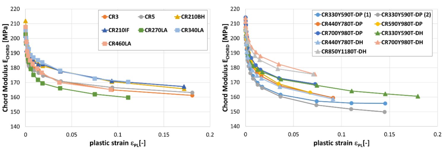
Reduction in chord modulus for mild steels and conventional high strength steels (left) and for DP and DH steels (right).W-10

Reduction in chord modulus for CP, CH and MS steels (left) and for a selected of hot rolled steels (right).W-10
Blog, RSW Modelling and Performance
Modern car bodies today are made of increasing volumes of Advanced High-Strength Steels (AHSS), the superb performance of which facilitates lightweighting concepts (see Figure 1). To join the different parts of a car body and create the crash structure, the components are usually welded to achieve a reliable connection. The most prominent welding process in automotive production is resistance spot welding. It is known for its great robustness, and easily applicable in fully automated production lines.
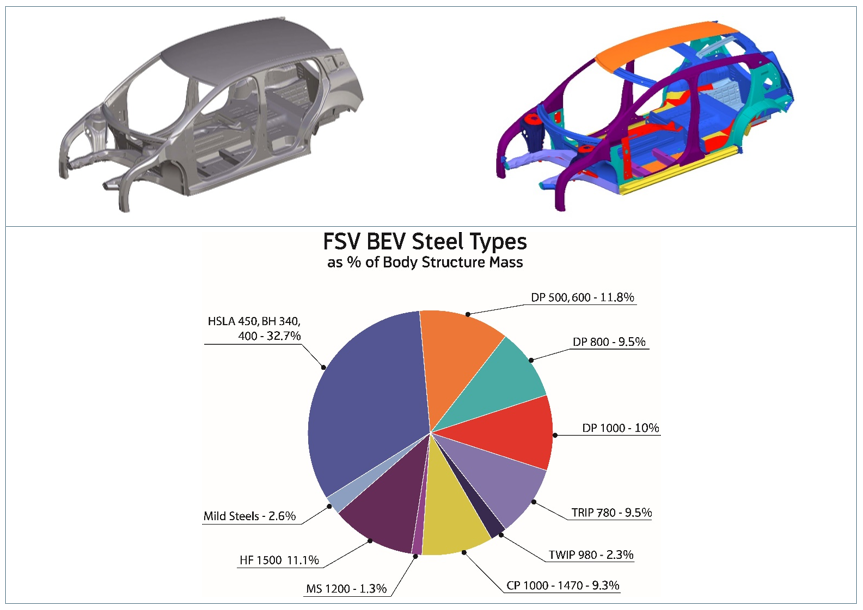
Figure 1: AHSS Content in Modern Car Body.W-7
There are, however, challenges to be met to guarantee a high-quality joint when the boundary conditions change, for example, when new material grades are introduced. Interaction of a liquefied zinc coating and a steel substrate can lead to small surface cracks during resistance spot welding of current AHSS, as shown in Figure 2. This so-called liquid metal embrittlement (LME) cracking is mainly governed by grain boundary penetration with zinc, and tensile stresses. The latter may be induced by various sources during the manufacturing process, especially under ‘rough’ industrial conditions. But currently, there is a lack of knowledge, regarding what is ‘rough’, and what conditions may still be tolerable.
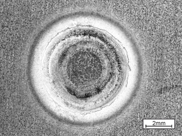
Figure 2: Top View of LME-Afflicted Spot Weld.
The material-specific amount of tensile stresses necessary for LME enforcement can be determined by the experimental procedure ‘welding under external load’. The idea of this method, which is commonly used for comparing cracking susceptibilities of different materials to each other, is to apply increasing levels of tensile stresses to a sample during the welding process and monitor the reaction. Figure 3 shows the corresponding experimental setup.

Figure 3: Welding under external load setup.L-51
However, the known externally applied stresses are not exclusively responsible for LME, but also the welding process itself, which puts both thermally and mechanically induced stresses/strains on the sample. Here, the conventional measuring techniques fail. A numerical reproduction of the experiment grants access to the temperature, stress and strain fields present during the procedure, providing insights on the formation of LME. The electro-thermomechanical simulation model is described in detail in Modelling RSW of AHSS. It is used to simulate the welding under external load procedure (see Figure 4).
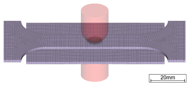
Figure 4: Simulation Model of Welding Under External Load.
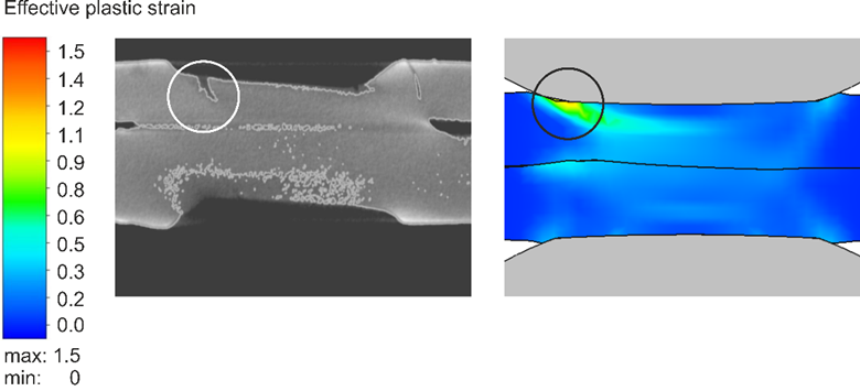
The videos that can be found in the link above show the corresponding temperature and plastic strain fields. As heat dissipates quickly through the water-cooled electrode, a temperature gradient towards the adjacent areas and a local temperature maximum on the surface forms. The plastic strains accumulate mainly at the electrode indentation area. The simulated strain field shows a local maximum of plastic deformation at the left edge of the electrode indentation, amplified by the externally applied stresses and the boundary conditions implied by the procedure. This area correlates with experimentally observed LME cracking sites and paths as shown in Figure 5.
The simulation shows that significant plastic strains are present during welding. When external stresses (in reality e.g. due to poor part fit-up or distorted parts) contribute to the already high load, LME cracking becomes more likely. The numerical simulation model facilitates the determination of material-specific safety limits regarding LME cracking. Parameter variations and their effects on the LME susceptibility can easily be investigated by use of the model, enabling the user to develop strict processing protocols to reduce the likelihood of LME. Finally, these experimental procedures can be adapted to other high-strength materials, to aid their application understanding and industrial set-up conditions.

Figure 5: LME Cracks in Cross Section View at Highly Strained Locations.
For more information on this topic, see the paper, co-authored by Fraunhofer and LWF Paderborn, documented in Citation F-23. You may also download the full report documenting the WorldAutoSteel LME project for which this work was conducted.

Blog, main-blog, RSW Modelling and Performance
Modelling resistance spot welding can help to understand the process and drive innovation by asking the right questions and giving new viewpoints outside of limited experimental trials. The models can calculate industrial-scale automotive assemblies and allow visualization of the highly dynamic interplay between mechanical forces, electrical currents and thermal flow during welding. Applications of such models allow efficient weldability tests necessary for new material-thickness combinations, thus well-suited for applications involving Advanced High -Strength Steels (AHSS).
Virtual resistance spot weld tests can narrow down the parameter space and reduce the amount of experiments, material consumed as well as personnel- and machine- time. They can also highlight necessary process modifications, for example the greater electrode force required by AHSS, or the impact of hold times and nugget geometry. Other applications are the evaluation of whole-part distortion to ensure good part-clearance and the investigation of stress, strain and temperature as they occur during welding. This more research-focused application is useful to study phenomena arising around the weld such as the formation of unwanted phases or cracks.
Modern Finite-Element resistance spot welding models account for electric heating, mechanical forces and heat flow into the surrounding part and the electrodes. The video shows the simulated temperature in a cross-section for two 1.5 mm DP1000 sheets:
First, the electrodes close and then heat starts to form due to the electric current flow and agglomerates over time. The dark-red area around the sheet-sheet interface represents the molten zone, where the nugget forms after cooling. While the simulated temperature field looks plausible at first glance, the question is how to make sure that the model calculates the physically correct results. To ensure that the simulation is reliable, the user needs to understand how it works and needs to validate the simulation results against experimental tests. In this text, we will discuss which inputs and tests are needed for a basic resistance spot welding model.
At the base of the simulation stands an electro-thermomechanical resistance spot welding model. Today, there are several Finite Element software producers offering pre-made models that facilitate the input and interpretation of the data. First tests in a new software should be conducted with as many known variables as possible, i.e., a commonly used material, a weld with a lot of experimental data available etc.
As first input, a reliable material data set is required for all involved sheets. The data set must include thermal conductivity and capacity, mechanical properties like Young’s modulus, tensile strength, plastic flow behavior and the thermal expansion coefficient, as well as the electrical conductivity. As the material properties change drastically with temperature, temperature dependent data is necessary at least until 800°C. For more commonly used steels, high quality data sets are usually available in the literature or in software databases. For special materials, values for a different material of the same class can be scaled to the respective strength levels. In any case, a few tests should be conducted to make sure that the given material matches the data set. The next Figure shows an exemplary material data set for a DP1000. Most of the values were measured for a DP600 and scaled, but the changes for the thermal and electrical properties within a material class are usually small.
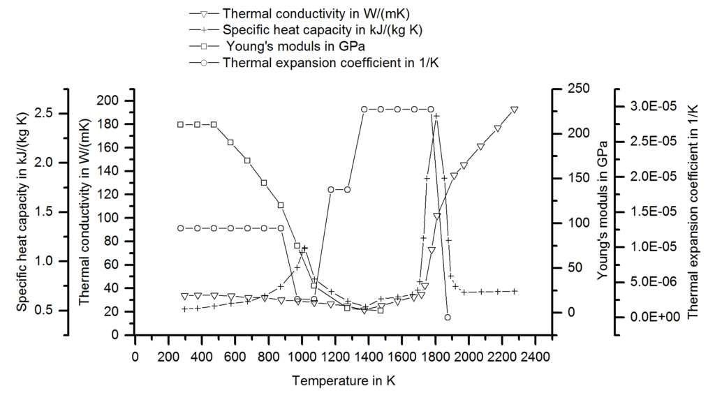
Figure 1: Material Data set for a DP1000.S-73
Next, meaningful boundary conditions must be chosen and validated against experiments. These include both the electrode cooling and the electrical contact resistance. To set up the thermal flow into the electrode, temperature measurements on the surface are common. In the following picture, a measurement with thermocouples during welding and the corresponding result is shown. By adjusting the thermal boundary in the model, the simulated temperatures are adjusted until a good match between simulation and experiment is visible. This calibration needs to be conducted only once when the model is established because the thermal boundary remains relatively constant for different materials and coatings.
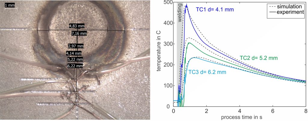
Figure 2: Temperature measurement with thermocouples during welding and the results. The simulated temperature development is compared to the experimental curve and can be adjusted via the boundary conditions.F-23
The second boundary condition is the electrical contact resistance and it is strongly dependent on the coating, the surface quality and the electrode force. It needs to be determined experimentally for every new coating and for as many material thickness combinations as possible. In the measuring protocol, a reference test eliminates the bulk material resistance and allows for the determination of the contact resistances using a µOhm-capable digital multimeter.
Finally, a metallographic cross-section shows whether the nugget size and -shape matches the experiment. The graphic shows a comparison between an actual and simulated cross section with a very small deviation of 0.5 mm in the diameter. As with the temperature measurements, a small deviation is not cause for concern. The experimental measurements also exhibit scatter, and there are a couple of simplifications in the model that will reduce the accuracy but still allow for fast calculation and good evaluation of trends.
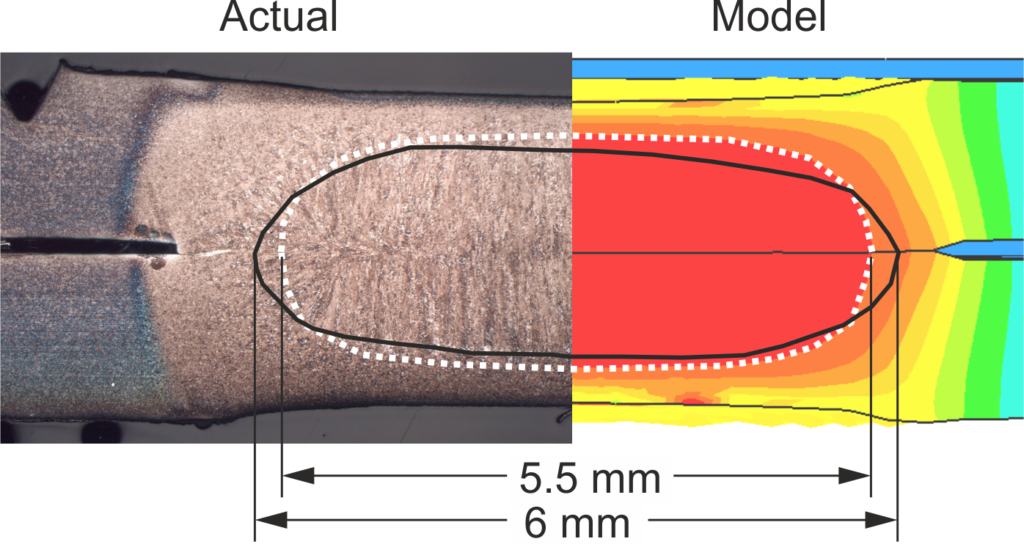
Figure 3: Comparison of experimental and virtual cross-sections.F-23
After validation, consider conducting weldability investigations with the model. Try creating virtual force / current maps and the resulting nugget diameter to generate first guesses for experimental trials. We can also gain a feeling how the quality of each weld is affected by changes in coatings or by heated electrodes when we vary the boundary conditions for contact resistance and electrode cooling. The investigation of large spot-welded assemblies is possible for part fit-up and secondary effects such as shunting. Finally, the in-depth data on temperature flow and mechanical stresses is available for research-oriented investigations, cracking and joint strength impacts.
Note: The work represented in this article is a part a study of Liquid Metal Embrittlement (LME), commissioned by WorldAutoSteel. You can download the free report on the results of the LME study, including how this modelling was used to verify physical tests, from the WorldAutoSteel website.


