
This article, contributed by ArcelorMittal, presents the first part of an in-depth study on the effects of residual elements such as Copper, Tin, Nickel and Chromium on the resistance spot weldability of automotive steels. Residual elements (also called tramp elements) can be introduced through impurities in steel recycling, raising the question whether the resulting steel’s performance may be impacted. Considering a broad range of residual elements and impurities, some slight changes in the welding behavior but no adverse effect on the weld results could be found.
This article is concerned with the weldability and hardness. A future article will investigate the mechanical properties of the spot welds.
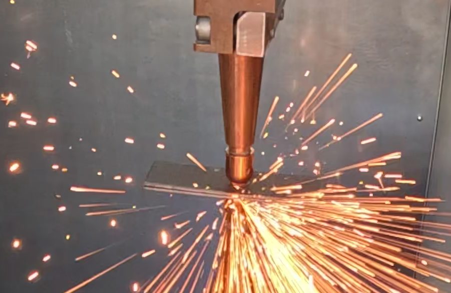
Why Residual Elements Matter for Spot Welding
EAF Steelmaking and Scrap-Borne Copper, Tin, Nickel and Chromium
Decarbonization of the steel industry implies a greater use of steel recycling, especially through the EAF (Electric Arc Furnace) process, which allows the remelting of scrap with limited CO₂ emissions—if the electricity used has been produced without CO2 emissions either, of course. However, a consequence of switching from BOF (Basic Oxygen Furnace) process to the EAF is that recycled scrap is prone to bringing unwanted alloying elements like Copper (Cu, from the electrical wires and motors), Tin (Sn, from packaging steels coatings), Nickel (Ni) and Chromium (Cr, from stainless steel scrap) which cannot be removed by secondary steelmaking process.
For the last few years, the question arose about the potential impact of these unwanted—or residual—alloying elements on the steel properties.
For the automotive market especially (where steels are usually produced through BOF process), the effect of such undesired elements on spot welding (the main joining process in car making) was investigated. Several weldability criteria can be considered, ranging from weld mechanical performance under different loadings, through operative weldability (welding current range).
Earlier Research on Tramp Elements and Spot Weldability
In an early study, the EAF and BOF processes were compared in resistance spot weldability. The study was published in a resistance welding seminar [1], and focused on two grades (a low carbon and a 590 MPa steel) produced by BOF and EAF. It was shown that the difference in physical properties due to residual elements was too small to produce any effect on the welding current range.
More recently, voestalpine presented a paper at International Institute of Welding Annual Assembly in July 2025 [2], introducing a method to study the influence of Cu in the nugget through digging a small hole at the surface of one sheet prior to welding, to insert directly a certain quantity of pure copper directly in the nugget during welding. They applied this method to a 600 MPa steel grade, showing no influence on cross-tension strength (CTS) and Tensile Shear Strength (TSS). But Cu was the only residual element studied, and the study was limited to 600 MPa steel grade.
In 2025 also, a paper was published and co-authored by Volkswagen [3]. Spot weldability of CR340LA GI, DP600 GI and 22MnB5 AS with 1500 MPa strength after processing from BOF and EAF processes was studied and compared, highlighting reduced CTS and increased Liquid Metal Embrittlement (LME) susceptibility for steels produced with EAF. These observations are supported by microstructural observations in HAZ (Heat Affected Zone) and micro-hardness profiles differences. Although the mechanisms and arguments proposed by this article are not fully convincing and partly contradictory with the two previous publications (concerning DP600), the difference in CTS reported for DP600 and Usibor grades seems statistically significant.
These contradictions and low number of publications on this topic highlight the need for broad testing to identify any risky case.
Scope: EAF and Residual-Added Steels vs. BOF References
In the past few years, several trials were organized inside ArcelorMittal to produce automotive steel grades either directly by EAF or simulating an EAF-like composition in steels produced by BOF, with controlled additions. Each time, reference samples with reference BOF process and limited residual content have been considered for comparison.
This report intends to present all the results obtained and discusses whether any additional risks occur due to higher residual element concentrations.
Materials and Test Methods
EAF, Residual-Added and Reference Steel Samples
In the past few years, several samples have been tested in RSW (Resistance Spot Welding).
- 6 samples were produced by EAF (Electric Arc Furnace);
- 7 samples were obtained with standard BOF (Basic Oxygen Furnace), but in which residual elements were intentionally added;
- 13 samples obtained through BOF were used as references, i.e. with standard composition in residual elements;
Table 1 concatenates information about all the tested samples, together with the Carbon Equivalent based on Nishi [4], without the embrittling elements P and S, i.e. Ceq = C + Si / 30+ (Mn + Cr) / 20.
Table 1: List of tested samples and chemical compositions (GI = Hot Dip Galvanized, AS = Aluminum-Silicon)
| Steel grade | Coating | Sheet gauge (mm) | Process | Label | Ceq |
|---|---|---|---|---|---|
| CR4 | GI | 0.75 | BOF with residuals addition | BH3483 | 0.010 |
| BOF reference | BH3480 | 0.010 | |||
| CR340LA | GI | 2.1 | BOF with residuals addition | BF0569 | 0.111 |
| BOF reference | BF0567 | 0.093 | |||
| CR380LA | GI | 1.15 | EAF | BH3515 | 0.086 |
| 1.2 | BOF reference | BB0485 | 0.090 | ||
| HR420LA | uncoated | 2.4 | EAF | BG0951 | 0.103 |
| 2 | BOF reference | AN0981 | 0.086 | ||
| HR460Y560T-FB | uncoated | 2.1 | EAF | BG0950 | 0.140 |
| HR400Y540T-FB | 2 | BOF reference | BF1789 | 0.157 | |
| CR440Y780T-DP | GI | 1.99 | BOF with residuals addition | BH0390 | 0.249 |
| 1.96 | BOF reference | BG2054 | 0.230 | ||
| 1.9 | BOF with residuals addition | BI1287 | 0.267 | ||
| 1.9 | BOF reference | BI1288 | 0.279 | ||
| CR700Y980T-DP-LCE | GI | 1.56 | BOF with residuals addition | BH0042 | 0.225 |
| 1.45 | BOF reference | BH0218 | 0.222 | ||
| PHS1000 (offered under the brand name Ductibor® 1000 by ArcelorMittal) |
AS | 1.4 | BOF with residuals addition | BH1293-AE | 0.174 |
| BOF reference | BH1301-AE | 0.170 | |||
| 22MnB5 (offered under the brand name Usibor® 1500 by ArcelorMittal) |
1.2 | BOF with residuals addition | BH1239-AE | 0.302 | |
| BOF reference | BH1235-AE | 0.306 | |||
| EAF | BG1594-AB-AA | 0.307 | |||
| BOF reference | BG1592-AB-AA | 0.309 | |||
| 1.4 | EAF | BF1160-AA | 0.280 | ||
| BOF reference | BD2328-AA | 0.304 | |||
| 1.5 | EAF | BG0462-AA | 0.292 | ||
| BOF reference | BC1188-AA | 0.306 |
For PHS (Press-Hardening Steels), the austenitization conditions (heat-treatment) are given in Table 2. The heat treatment conditions are the standard recommended depending on the coating and sheet thickness.
Table 2: Heat-Treatment conditions for Press-Hardening Steels
| Steel grade | Coating | Thickness (mm) | Process | Label | Heat treatment temperature | Heat treatment time |
|---|---|---|---|---|---|---|
| PHS1000 | AS | 1.4 | BOF with residuals addition | BH1293-AE | 900°C | 6 minutes |
| BOF reference | BH1301-AE | |||||
| 22MnB5 | 1.2 | BOF with residuals addition | BH1239-AE | 6 minutes | ||
| BOF reference | BH1235-AE | |||||
| EAF | BG1594-AB-AA | 5 minutes | ||||
| BOF reference | BG1592-AB-AA | 5 minutes | ||||
| 1.4 | EAF | BF1160-AA | 6 minutes 20 s | |||
| BOF reference | BD2328-AA | 7 minutes | ||||
| 1.5 | EAF | BG0462-AA | 6 minutes 30 s | |||
| BOF reference | BC1188-AA |
Test Standards: ISO 18278-2 and SEP 1220-2
Table 3 gives the list of tests performed on each sample, listing the welding current range standard used (ISO 18278-2 or SEP 1220-2) and current type (50 Hz or MFDC).
Table 3: Tests performed
| Steel grade | Coating | Thickness (mm) | Process | Label | Welding current range (homogeneous) |
|---|---|---|---|---|---|
| CR4 | GI | 0.75 | BOF with residuals addition | BH3483 | SEP 1220-2:2024 (50 Hz) |
| BOF reference | BH3480 | ||||
| CR340LA | GI | 2.1 | BOF with residuals addition | BF0569 | ISO 18278-2:2016 (50 Hz) |
| BOF reference | BF0567 | ||||
| CR380LA | GI | 1.15 | EAF | BH3515 | ISO 18278-2:2016 (50 Hz) |
| 1.2 | BOF reference | BB0485 | |||
| CR420LA | uncoated | 2.4 | EAF | BG0951 | ISO 18278-2:2016 (50 Hz) |
| 2 | BOF reference | AN0981 | ISO 18278-2:2004 (50 Hz) | ||
| HR460Y560T-FB | uncoated | 2.1 | EAF | BG0950 | ISO 18278-2:2016 (50 Hz) |
| HR400Y540T-FB | 2 | BOF reference | BF1789 | ||
| CR440Y780T-DP | GI | 1.99 | BOF with residuals addition | BH0390 | SEP 1220-2:2011 (50 Hz) |
| 1.96 | BOF reference | BG2054 | SEP 1220-2:2011 (50 Hz) | ||
| 1.9 | BOF with residuals addition | BI1287 | SEP 1220-2:2024 (50 Hz) | ||
| 1.9 | BOF reference | BI1288 | SEP 1220-2:2024 (50 Hz) | ||
| CR700Y980T-DP-LCE | GI | 1.56 | BOF with residuals addition | BH0042 | SEP 1220-2:2011 (50 Hz) |
| 1.45 | BOF reference | BH0218 | |||
| PHS1000 | AS | 1.4 | BOF with residuals addition | BH1293-AE | SEP 1220-2:2024 (MFDC) |
| BOF reference | BH1301-AE | ||||
| 22MnB5 | 1.2 | BOF with residuals addition | BH1239-AE | SEP 1220-2:2024 (MFDC) | |
| BOF reference | BH1235-AE | ||||
| EAF | BG1594-AB-AA | SEP 1220-2:2011 (MFDC) | |||
| BOF reference | BG1592-AB-AA | ||||
| 1.4 | EAF | BF1160-AA | |||
| BOF reference | BD2328-AA | ||||
| 1.5 | EAF | BG0462-AA | ISO 18278-2:2016 + SEP 1220-2:2011 (50 Hz) | ||
| BOF reference | BC1188-AA | SEP 1220-2:2011 (50 Hz) |
The tests done consisted in welding current range tests, either according to ISO 18278-2 [5], or according to SEP 1220-2 standard [6]. Both standards now specify the same welding parameters. However, some tests were performed with the older version of SEP 1220-2 (2011), for which some of the welding parameters differed from ISO 18278-2 (esp. the electrode tip size for thinner sheets, fixed at 5.5 mm vs 6 mm in ISO 18278-2). All welding parameters used are given in Appendix. Beyond the welding parameters, the testing procedure differs between both standards. Especially, the welding range limits are analyzed after the test in ISO 18278-2, while they are sought with current level refinement and specific criteria in SEP 1220-2, which may sometimes influence the results of the welding current range limits. 4√t was used as a minimum weld diameter for Imin with both standards (knowing that ISO 18278-2 lets this choice open).
Also, while both standards are rather open about the type of samples and destructive technique used during the test, CTS (Cross-Tension Strength test) was systematically used along the welding range tests, allowing richer diameter/strength curves. Tensile-Shear Strength testing was also performed, either at Imin and Imax as specified by SEP 1220-2, or along the welding range (using the third spare sample at each current step) when following ISO 18278-2. Additionally, Paint Baking (170°C during 20 minutes) was sometimes applied on some CTS and TSS samples just after welding, to assess the influence of this thermal treatment on weld strength. While this is now specified in the latest version of SEP 1220-2 only, it was already applied here in several studies.
Do Residual Elements Change the Welding Current Range?
The welding current range results, obtained with either standard (ISO 18278-2 or SEP 1220-2), are shown below. Results are grouped by type of steel (for cold stamping, or hot pressed). On the graphs, only the spot welds tested in Cross-Tension are shown.
Cold Stamping Steels: CR4, HSLA, FB and DP Grades
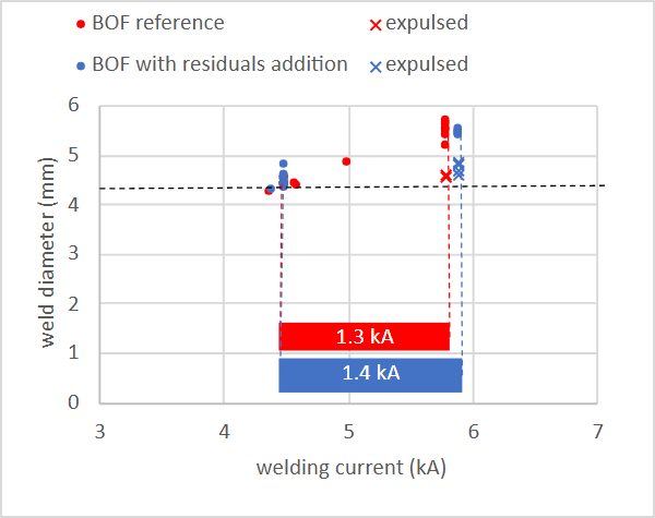
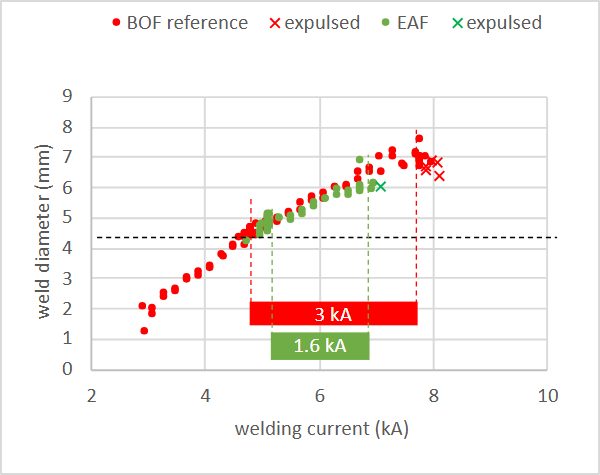
Welding current range curves and results are displayed on Figure 1 to Figure 5 for cold stamping steel grades.
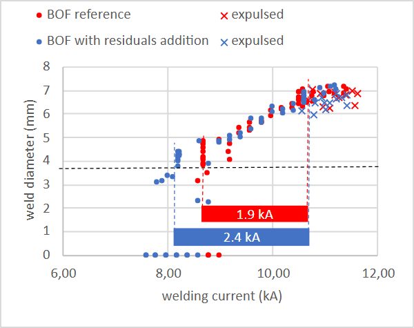
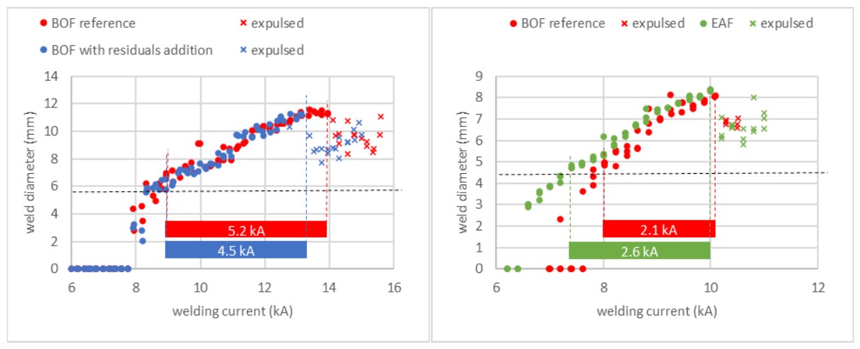
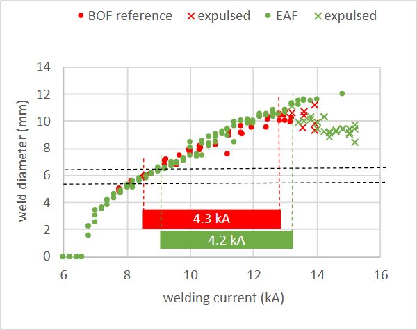
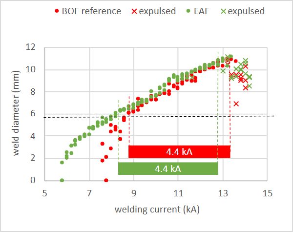
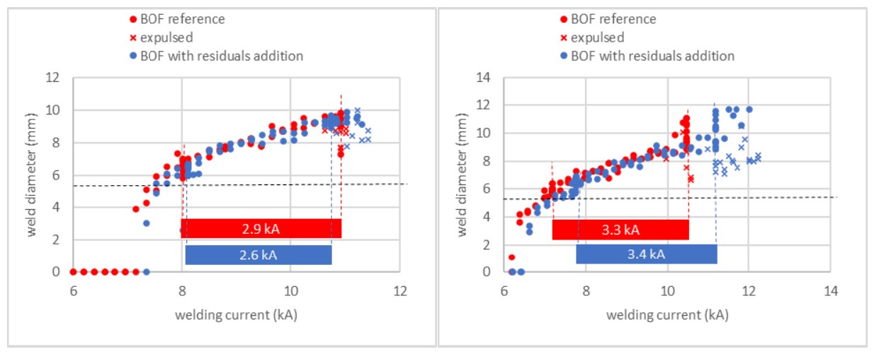
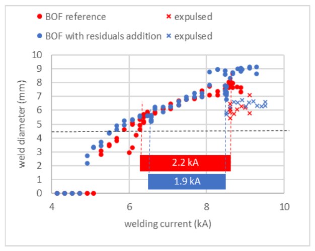
It is noteworthy that weld growth curves appear wide (compared to a typical 1 kA criterion) and almost systematically superimposed for reference and residual-added grades. In few cases (CR380LA GI in Figure 2, FB uncoated in Figure 3, CR700Y980T-DP-LCE GI in Figure 5), there is a trend toward a slight shift of the curve with residuals toward lower currents, only for the lower end of the current range. This could be due to a slight effect of residual elements on physical properties.
In terms of welding range limits and width, they also appear to be aligned in each case between the reference and the grade with residuals, although some fluctuations can be found. These slight differences can be attributed:
- to growth curve slight shift noticed previously;
- to slight thickness differences in comparisons;
- and of course to RSW process scatter.
Paying more attention to the welding range upper limit (expulsion limit), no clear trend appears since the expulsion limit is sometimes higher and sometimes lower when residuals are added.
Overall, the welding current range appears much more determined by the steel grade and thickness (hence the welding parameters defined by the standards), than by the presence of residuals in the chemistry.
Press Hardening Steels: PHS1000 and 22MnB5
Welding current range curves and results are displayed on Figure 6 to Figure 8 for press hardening steel grades after hot stamping.
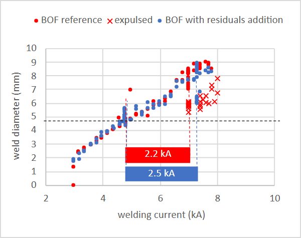
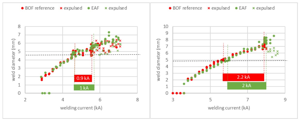
Like for cold stamped steels, the weld growth curves appear closely superimposed in all comparisons for Press Hardened Steels. Welding range limits again show some differences due to process scatter or other reasons. Concerning PHS, it is well known that the expulsion limit is often unstable, and in the above examples it shows sometimes significant differences between the reference sample and the sample with residuals. However, no global trend can be found, i.e. the addition of residuals sometimes shifts the expulsion limit to higher currents, but sometimes also to lower currents.
Spot Weld Microsections and Hardness Profiles
Cross-sections and hardness profiles are not available for all grades tested, since this characterization is not included in ISO 18278-2 procedure. CR4 and HSLA steels results are considered first, since specific phenomena arise for these steel grades. DP grades and PHS will come at last.
CR4 and HSLA Steels: Why Residuals Raise Nugget Hardness
The micro-sections at minimum and maximum current of the current welding range in homogeneous configuration of IF steels are shown on Figure 9.
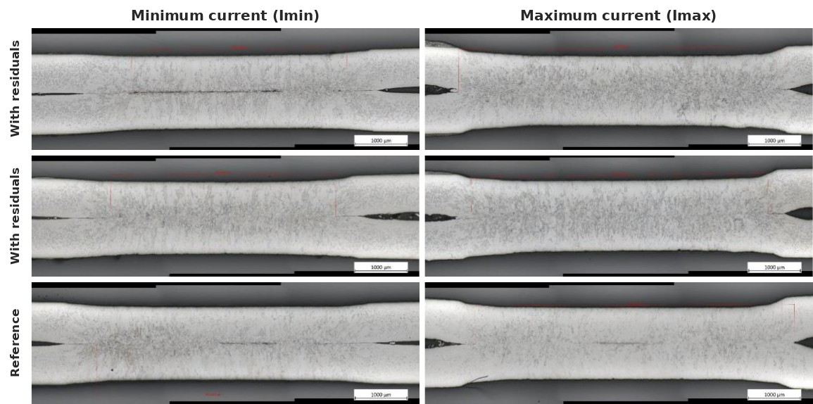
Some ring nuggets are revealed by these images, i.e. welds where the center is not molten. This is the case especially at Imin, which is expected for such grade/thickness. However, the differences between both materials in terms of ring nugget occurrence are not considered as significant, since large differences can be found between cross-sections of the same material welded in the same conditions.
The hardness profiles of CR4 and CR340LA steels homogeneous welds are shown on Figure 10 and Figure 11.
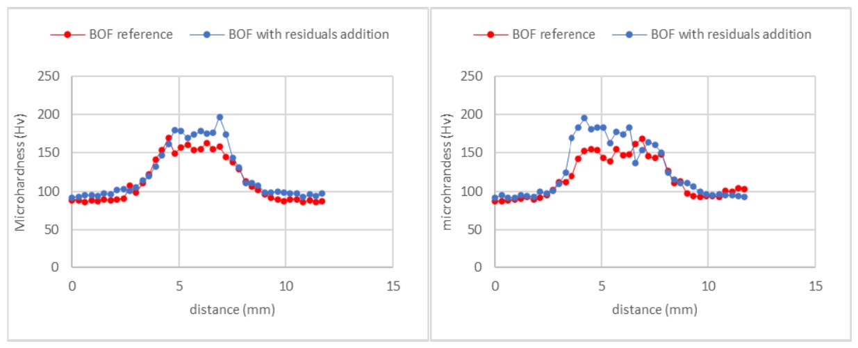
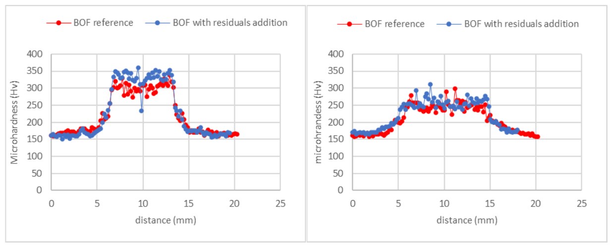
The hardness of the quenched nugget is clearly higher for the metal with residuals in the case of CR4 steel, and in the case of CR340LA at Imin, but not for CR340LA at Imax. The reasons for this situation are supposed to be the following:
- For CR4 grade, the weld zone contains probably a large amount of ferrite (because of the low alloying content of the grade), which appears to be hardened compared to base metal, probably through solid solution hardening. The presence of residual elements like Cu, Ni and Cr can enhance this solid solution hardening [7].
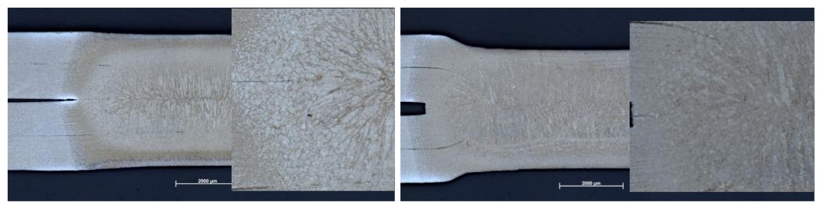
- For CR340LA at Imax, the microstructure of the weld is expected to be mainly bainitic (Figure 12 right) at 250 Hv, and residual elements are not expected to influence significantly martensite or bainite hardness [8], showing no difference between both grades.
- For CR340LA at Imin, the thermal inertia is less than at Imax (since less heat was input in the weld), leading to higher cooling rate and globally higher quenching; the hardness measured (300 to 350 Hv) corresponds to a situation where a significant amount of martensite is present in the weld microstructure (Figure 12 left). The addition of residual elements is expected to increase quenchability of the grade, thus forming more martensite and increasing the hardness (even if the individual hardness of the bainitic and martensitic fractions are not modified).
However, such differences in nugget hardness are not expected to influence the spot weld properties (strength), since for this kind of grade the weld fracture occurs around the nugget in the Heat Affected Zone or in the base metal (plug failure), and is not influenced by the nugget hardness nor properties.
Dual Phase Steels: No Measurable Residual Effect
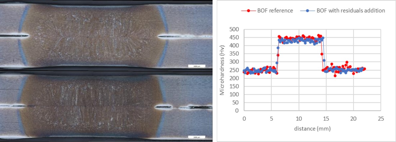
For DP grades, it has been found overall that no impact of residuals could be detected when comparing cross-sections or microhardness profiles for most grades: the case of galvanized CR4 or HSLA steels shown above is specific since the alloying content of the reference metal is very low, giving an increased relative importance to the addition of residuals on physical properties and hardness after quenching. For other grades, the alloying content is much higher so that the impact of residuals addition is insignificant on nugget development of microhardness, since the nugget is martensitic and martensite hardness is not affected by residuals. This can be verified in the following figures, showing a few comparisons first for galvanized CR440Y780T-DP and CR700Y980T-DP-LCE.
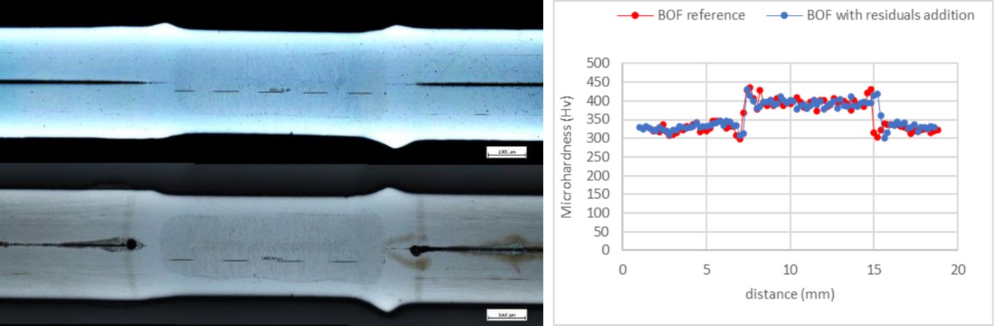
Press Hardening Steels: Matching Hardness Profiles
Microsections and hardness profiles for PHS1000-AS and 22MnB5-AS in 1.2 and 1.5 mm are shown on the following figures.
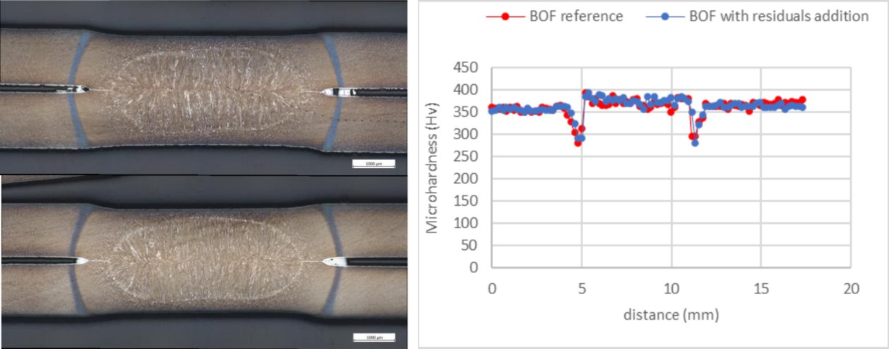
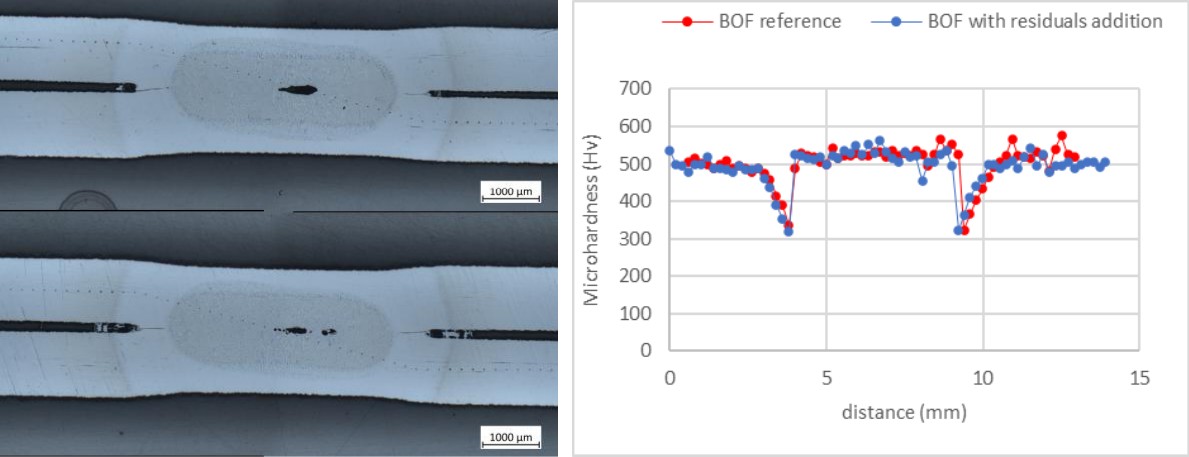
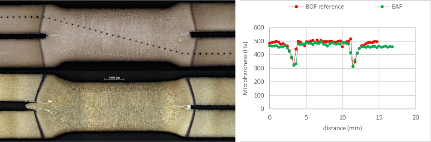
All these microsections and hardness profiles show similarity between reference grade and sample with residuals. In one of the last comparisons (Figure 17), a slight difference of hardness can be noticed both for base metal and nugget, the reference material being harder. This difference is suspected to be due to the carbon equivalent difference between both materials (0.292 vs 0.306), such a difference being able to explain a ~20 Hv difference in hardness based on standard formula for martensite hardness prediction, for example [9].
Conclusions: Residual Elements and Spot Weld Quality
This work reports resistance spot welding tests carried out on almost 15 samples containing residual elements, compared to reference samples. Studied grades range from coated and uncoated CR4 steels to 1500 MPa grades, both for cold stamping and press hardening steel grades after hot stamping. Several weldability criteria have been considered, including welding current range, weld strength in CTS and TSS, and hardness profiles.
Globally, the results obtained with the samples with or without residual elements are identical, and no impact of these residuals can be highlighted. Sometimes, differences can be explained by other variations between the samples, the base chemistry showing also some variations between the samples.
In only a few cases, an influence of residual elements is suspected: for very low alloyed grades (CR4 or HSLA), the hardness in the weld can be increased by the presence of residual elements, due to higher quenchability or hardenability. However, this doesn’t play a role on weld strength, since spot welds fail by base metal plug fracture for such steels.
Acknowledgement

Thomas Dupuy, ArcelorMittal
Thomas DUPUY has been working on resistance welding for 30 years. Inside ArcelorMittal Global R&D, he is the leader of a team dedicated to weldability of steel sheets for automotive applications in Maizières-les-Metz, France
The welding tests and characterizations have been carried out by Jérôme Dap, Tarik Loubiri, Lucas Filippini, Benjamin Dorckel, Philippe Fischer and Baptiste Paulus.
Stéphanie Michaut, Outhmane Siar, Xiaolei Chen and Christine Kaczynski have contributed to the testing organization and results analysis.
References
- Elliot Biro and Thomas Dupuy, Effect of Steel Processing Chemistry Variation on Resistance Spot Welding, 5th International Seminar on Advances in Resistance Welding, Toronto, Canada September 24th – 26th (2008)
- L. Arbinger, R. Sierlinger N. Enzinger, Method to systematically investigate the effect of tramp elements in resistance spot welding Int. Inst. Welding ref III-2370-25 (2025) https://link.springer.com/article/10.1007/s40194-026-02341-1
- Elias Gebhard Vogt, Patrick Veyel, Lars Gebel, Christian Meyer, Robert Thomas, Michael Thomas, and Christoph Herrmann, Influence of Higher Tramp Element Level on the Weldability of Automotive Steels, Steel Research Int. 2500240 (2025) https://onlinelibrary.wiley.com/doi/10.1002/srin.202500240
- Nishi, T.: Evaluation of Spot Weldability of High strength Sheet Steels for Automobile Use. Seitetsu Kenkyu. (307), 56 (1982)
- ISO 18278-2:2016, Resistance welding — Weldability — Part 2: Evaluation procedures for weldability in spot welding (2016) https://www.iso.org/standard/52317.html
- SEP 1220-2:2011 and :2024 Testing and Documentation Guideline for the Joinability of thin sheet of steel – Part 2: Resistance Spot Welding (2011, 2024)
- V. Daeschler, O. Buggenhoudt, C. Oberbillig, F. Bonnet, Determination of solid-solution hardening coefficients of substitutional elements based on advanced combinatorial metallurgy, report 2025 31952 RDAP (2025)
- Junaidi SYARIF et al, Effect of solute copper on yield strength in dislocation-strengthened steels, Tetsu-to-Hagane Vol. 91 No. 11 (2005) https://www.jstage.jst.go.jp/article/isijinternational/47/2/47_2_340/_article
- BLONDEAU, R. et alii.: Mathematical Model for the Calculation of Mechanical Properties of Low-Alloy Steel Products: A Few Examples of its Application. In: 16th International Heat Treatment Conference – Heat Treating ‘76, The Metals Society Stratford-upon-Avon, 189-200 (1976)