This article explores the challenges of liquid metal embrittlement (LME) in resistance spot welding (RSW) of automotive components, particularly focusing on a component-scale S-Rail made from advanced high-strength steel (AHSS). The study aims to identify the occurrence of LME during the welding process and to propose effective strategies for its mitigation. This article is an excerpt from the “LME component study” conducted by WorldAutoSteel. The full study can be downloaded here.
Experimental and Simulative Setup
The experiments utilized an electrogalvanized RA1180 AHSS joined to hot-dip galvanized mild steel. Two stack-up configurations were tested: similar (both sheets made of RA1180) and dissimilar (RA1180 on top of mild steel). The resistance spot welding process was monitored using sensors to record current, voltage, and force. Different welding parameters, such as hold time and electrode geometry, were varied to observe their effects on LME.
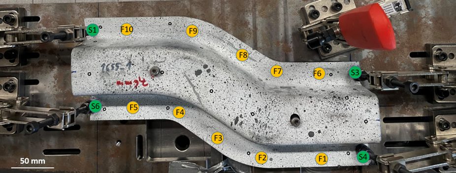
Figure 1: Top-view of the S-Rail component during welding. The clamping points S1-S4 as well as the welding points F1-F10 are highlighted.
A simulation-based risk criterion for LME was established based on local stresses in the components. Both experimental and numerical analyses were conducted to assess the influence of various parameters on LME formation. Specifically, the study evaluated how springback, a phenomenon occurring during deep drawing, affects LME risk. Correct clamping can effectively suppress springback, consequently reducing LME occurrences.
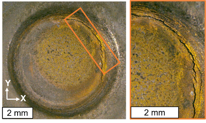
Figure 2: Experimentally observed cracks with 5° tilted electrodes and doubled welding time of 760 ms.
Findings
- Influence of Springback: Springback contributed to LME formation. When clamping was employed to counteract springback, LME was effectively eliminated from the welded samples.
- Electrode Geometry and Hold Time: Adjustments to the electrode geometry and increasing hold time after welding further mitigated LME risks. Specifically, larger electrode tip diameters and longer hold times reduced the likelihood of cracks.
- Material Stack-up Effects: The experiments indicated that the configuration of the material stack-up influenced LME occurrences. Only stack-ups with thick joining partners showed occurrence of LME in the trials.
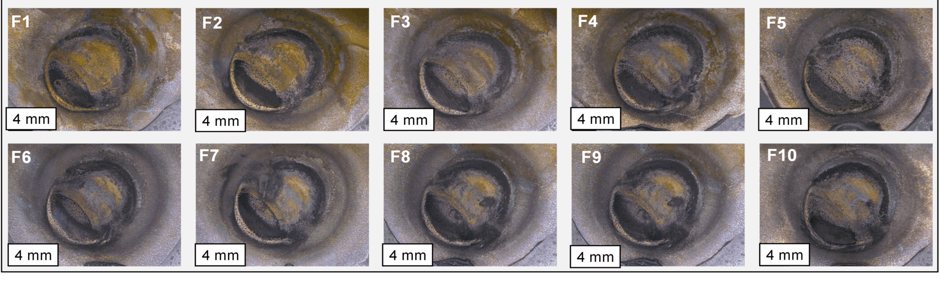
Figure 3: All 10 resistance spot welds on the S-rail are crack-free after optimizing either springback, electrode working plane diameter or post-weld hold time
Simulation Results
Finite element simulations were used to evaluate the risk of LME by analyzing local stresses and temperature distributions during welding. The results showed that the springback-affected samples presented a higher LME risk compared to idealized, straightened models. This finding aligns with experimental observations that cracks occurred where excessive springback influenced the welding process. Even in the case of springback, LME could be effectively prevented by using electrode caps with larger working planes as well as slightly extending the hold time after welding.
The developed simulation approach allows comparing the LME conditions for different welding setups and can therefore optimize the LME occurrence for geometry, material and welding conditions.
Conclusion
Effective mitigation strategies, such as clamping to suppress springback and adjustments in welding parameters, can prevent LME on a component-scale. It can also be highlighted that today’s AHSS grades are far less sensitive to LME by-default so that few RSW joints in a whole body-in-white are at all susceptible for cracking: To produce cracks for this study, welding parameters with increased energy input had to be used; no LME was observed under “standard” industrial conditions.