An increasing number of laboratories are using Digital Image Correlation (DIC) to enhance and refine the data captured during testing. DIC is a technique used to measure displacement and deformation using optical and computational tools. Measurement accuracy depends on the proper use of camera, lenses and lighting to capture the movement of a spatter pattern applied to the material sample. Setting up optical equipment requires the operator to understand camera resolution, frame rates, buffering, lens field of view, aperture sizes, depth of field, plane of focus, and the impact of lighting on exposure, shadow, contrast and focus.
The challenges of focusing on a planar surface are different from those of a three-dimensional surface. Where a planar surface can support a ‘focus and shoot’ approach, a 3D surface requires an understanding of depth of field, multi-camera setup and aperture size.
The Camera
The camera is a dark box that has a mount for a lens and a sensor to capture and store light from the lens image. At its most basic, you can make a camera using film and an oatmeal box with an opaque lid. If you puncture the center of the lid with a pin and mount a piece of film on the back, your oatmeal box camera can capture images. Capturing the image requires you to cover the pinhole with something opaque and remove it until enough light enters the box to expose the film.
Modern cameras operate under the same principles as the oatmeal box. Today’s digital cameras use electronic sensors instead of film and include sophisticated controls to manage:
- focus,
- the amount of light that enters the camera,
- the photographer’s preference for what controls they want to manage and what will be automated, and
- the sensitivity of the image sensor
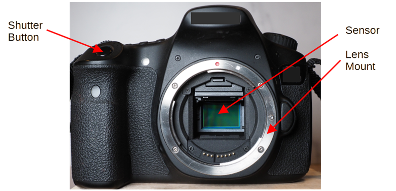
Figure 1: Key control locations on modern cameras.
There are a number of important considerations when purchasing a camera for use in DIC. Each consideration affects the quality of the images you capture and the accuracy of your displacement measurements.
- Resolution
Camera resolution is the amount of detail captured by the image sensor. This is most often represented as either recorded megapixel count or the number of pixels across the horizontal and the vertical axis. A 12 Megapixel sensor (12 MP) measures 4,000 pixels wide by 3,000 pixels tall. A higher MP sensor of the same size is referred to as having a higher pixel density. Sensors also have non-recorded pixels that support the capture of additional useful information.
Higher resolution means greater data capture. This means more detail in the image, but greater data capture means longer times to offload information from the sensor to the buffer, then to data storage. In high-speed photography, lower resolutions can be preferable because data is stored faster and camera buffers can be smaller. Also, large image files take longer to manage and process.
- Speed
Shutter speed defines how fast the shutter can open and close to expose the sensor. Sensor sensitivity defines how the camera sensor responds to levels of light. Sensitivity is measured in what is termed ISO, an acronym for the International Organization for Standardization . A higher ISO sensor is able to capably capture and record lower levels of light. High speed cameras capture hundreds or even thousands of images per second. This means that the sensor is exposed to very short bursts of light.
- Buffer
The buffer is the in-camera memory that stores images right off the sensor and off-loads it to your permanent storage location. The buffer must be fast enough to store the data right off the sensor before the next image. Storing to the buffer is fast, but offloading to permanent storage takes a bit longer. Your buffer should be large enough to store all your high speed images before filling and stopping your shooting.
The Lens
Today’s lenses are precision optical devices. The lens generally manages focus and the volume of light that hits the sensor. Unlike the pinhole camera described above, a lens collects a larger amount of light that can be controlled to manage the quantity of that light which projects on the sensor. The lens can focus on a selected range of subjects. Considerations for selecting a lens include focal length, largest aperture size, and whether it includes a depth of field scale.
- Focal Length
Focal length is an important feature of the lens. Technically It is the distance of the rear of the lens to the sensor. A shorter lens displays a wider angle of view on the sensor, while longer lenses display a more narrow view. This means that shorter lenses project more of the scene while a longer lens will make the subject appear larger. For DIC, you want a lens appropriate for the size of your sample. The sample and spatter pattern will be easier to read and interpret if it displays larger on the sensor.
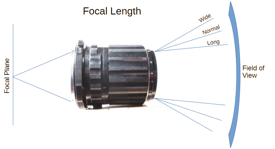
Figure 2: Relationship between focal length and field of view.
- Aperture
The aperture (called f-stop) is the diameter of the lens opening. It is expressed in relation to the diameter of the opening as a fraction of the focal length. A focal length of f/1 is larger than a focal length of f/16. The aperture affects two elements of the image production: it controls the amount of light that passes through the lens and it affects the Depth of Field. Depth of Field is the distance from the focal point that the image will be acceptably sharp. Generally, smaller apertures have a larger Depth of Field.
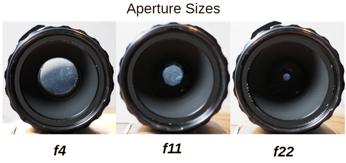
Figure 3: Relative aperture size for 3 f-stops.
- Depth of Field Scale
Depth of field scales are index marks on the barrel of the lens showing the range of ‘acceptable focus’ for each f-stop. This tells you the minimum and maximum distance where focus is acceptably sharp.
Lighting
The quality of your lighting is arguably the most critical component of your success. There are several types of light sources available. Your goal in lighting is to evenly light the sample surface, provide soft lighting, consistent light output, reduce heat, and color management. Techniques to light your sample properly include:
- Even lighting
Shining lights across flat and deformed surfaces is a trial and error process. The best alternative is to use a light meter to measure the intensity of your light across your field. You can use your eyes, but setup will both create additional scrap and take more time than using a light meter. The light meter measures the value of the light where you place the sensor and recommend the best f-stop for your shutter speed. As a three-dimensional dome is deformed during testing, there will be light variability across the deforming surface. If the measured variability is kept within ½ f-stop, today’s cameras can compensate for the range of variability in your lighting. - Soft Lighting
A lighting panel with a diffuser can help soften the light generated by the light source. Also, the closeness of the light source to the test sample affects the softness/harshness of the light. A light placed closer to the subject will provide a softer quality light. As you move the light source away from the deforming test piece, it becomes a smaller light point and will project harsher light and shadows. - Consistent Output
Modern constant lights do well at providing consistent light color and quality. Fluorescent lights are a poor choice because they flicker. If possible, connect your lights to a circuit that isn’t subject to heavy loads that will impact the feed to your light source. - Heat Management
Some lights generate a lot of heat. Tungsten lights get very hot during operation. If your lights heat your sample, they may affect the output of your test. Likewise, white lights include all the colors in the visible spectrum and may include infrared. Infrared light may also warm your sample. LED panels are a good alternative if your are testing materials subject to variability from warming. - Color Management
White light isn’t really a color, but includes all colors in the visible spectrum. The colors in the spectrum have different wave lengths. Colors focus at a different point behind the lens. This is known as chromatic aberration. Chromatic aberration causes the ‘color fringing’ you may notice in the details of some photographs. For the software to follow the displacement of contrast areas on the speckle pattern, it is best to avoid reducing the sharpness of the contrast with color fringing. Some high-end lenses are designed to reduce chromatic aberration. Some testing labs manage chromatic aberration by placing a blue filter on the lights. Blue filters can reduce chromatic aberration, minimize glare, and reduce the impact of infrared light on your sample.
2D and 3D Measurement
Two-Dimensional measurement is a single camera setup that works best when the camera is set up perpendicular to the specimen. Although it’s commonly assumed that 2D only supports in-plane surfaces, it can be useful for out-of-plane applications when the deformed specimen remains within the lens’ depth of field.
An advantage of 2D DIC is that it is easy to set up with less hardware. Disadvantages include inaccurate readings when the deformed surface exceeds the lens’ depth of field and it can be affected by perspective distortion introduced by wider lenses.
Three-Dimensional measurement requires two cameras whose fields of view overlap. This setup is ideal for measuring out-of-plane motions, complex geometries and large deformations.
The advantages of 3D measurement include its ability to measure a full 3D shape, displacement and strain fields. Among its disadvantages are the need for continuous camera calibration, the need for a stable stereo camera rig and the need to synchronize image acquisition.
Tips for Successful Optical Setup
- Choose a camera compatible with your DIC software that provides enough resolution to capture the speckle pattern but allows for flexibility in camera speed.
- Choose cool lights and use a blue filter. LED light panels are cooler than tungsten lights.
- Choose a lens appropriate for the size of your sample. This should provide coverage of the entire area of interest with enough room to provide a small margin.
- Focus your lens manually. Autofocus systems vary your focal point and can provide inaccurate information.
- Use lenses with Depth of Field scales and understand how to use them. This will allow you to provide enough in-focus coverage for the movement of your field of interest.
- Anticipate the amount of movement in a deformation test. Set your focal point and Depth of Field for your expectations and adjust them for actual results.
- Consider your DIC tests as experiments. You will need to learn from your tests and adjust your optical equipment until you get accurate results.
More information about these topics can be found in “A Good Practices Guide for Digital Image Correlation” from International Digital Image Correlation Society, Citation I-26.
 Thanks are given to Bill Frahm, a partner with 4M Partners for his contributions to this page. Bill supports the sheet metal forming industry’s efforts to manage the opportunities and risks of Smart Manufacturing. Sheet metal forming is a fragmented industry. Much of the work forming components is done by small to mid sized manufacturers. These companies are often resource constrained. The latest knowledge about materials, processes, and tools aren’t readily available to employees. Bill’s professional goal is to provide employees with the knowledge and confidence to understand the analysis of smart manufacturing, manage analysis efforts to support their goals, and control data and data products to prevent misuse and bias.