
In automotive pre-production, building physical prototypes to test weld distortion is both costly and time-consuming. These distortions can create major challenges during production ramp-up, including poor part tolerances and visible warpage in outer panels. Welding distortion simulation helps address these risks early by predicting distortion before the prototype is built and by enabling countermeasures before manufacturing issues occur.
Why Welding Distortion Matters in Automotive Design
In automotive manufacturing, key decisions about welding equipment, fixtures, and process design are often made before physical testing of weld distortion and part tolerances can take place. This can result in delays, rework, and additional costs during start of production (SOP). Simulation of welded structures and subsequent distortion management enable proof of concept at an early stage, saving cost and time during design and development of both components and production lines for new vehicles.
Advanced high-strength steels (AHSS), deployed throughout the vehicle body structure in applications such as longitudinal beams, sills, upper and lower crossmembers, passenger safety cage, and other components are particularly sensitive to welding-related shape deviations because of their high strength and stiffness. This makes welding distortion analysis an important part of the design process. Modern welding simulation software can predict distortion effects based on component geometry, material properties, clamping conditions, and welding process parameters.
Building and Calibrating the Simulation Model
As with any numerical simulation, reliable welding distortion prediction depends on the quality of the input data. For both AHSS and mild steels, material datasets are available in the literatureP-9 and provide good predictive accuracy for standard material classes. Accuracy can be improved further by measuring the properties of the specific material being used and modifying existing datasets.
Additional inputs are process-related: geometry, clamping locations, and welding sequences must be defined for each weld and included in the model. To keep computation times practical, the welding process itself is simplified by neglecting arc or laser interaction with the material by applying an equivalent heat input to the component.
Because this simplified heat input does not directly correspond to a single physical parameter, it must be calibrated using experimental data. Figure 1 illustrates a calibration approach that compares metallographic cross-sections from experiments with simulated molten zones for two different laser-welded joints.
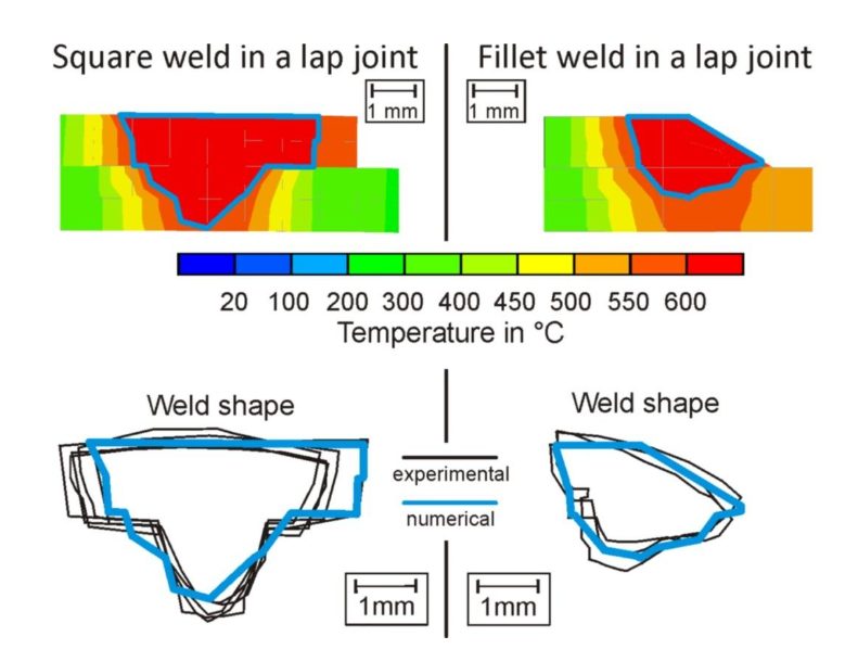
Figure 1: Calibration of numerical simulation heat input by comparing the molten zone between experiment and simulation.
Validating Results and Optimizing Distortion Control
Once the model inputs are defined, the simulation can be run to calculate temperature evolution, material response, and distortion during and after welding. Figure 2 shows a comparison between simulated and measured distortion in an automotive door structure. The strong alignment demonstrates that the model can reliably capture the main distortion mechanisms and can be used to assess distortion-related risks before SOP. The illustrated inner panel is the main part of the door assembly, to which several reinforcements and door components are joined. Therefore, different material-thickness combinations must be considered.
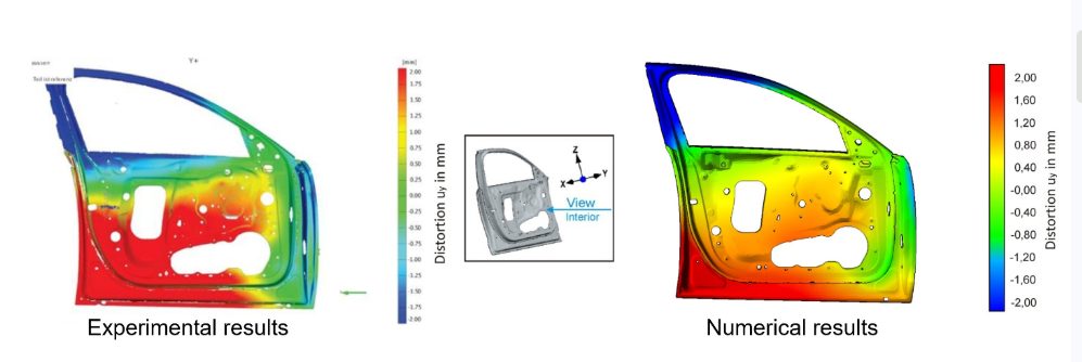
Figure 2: Comparison of measured and calculated distortion of an automotive door structure. A good agreement between the numerical prediction and experimental tests can be achieved with welding simulations.T-49
The real value of simulation becomes even clearer after the initial model has been validated. Based on the calibrated model, design and process variants can be evaluated with relatively little additional effort. This shifts part of the optimization process from costly physical trials to welding distortion simulation.
Figure 3 shows one such example: a variant with increased clamping time after welding. Allowing the component to cool longer in the fixture can reduce overall distortion, although it may also increase production cycle time. Other potential variants include modified welding sequences, adjusted clamping locations, or geometric changes to the component itself.
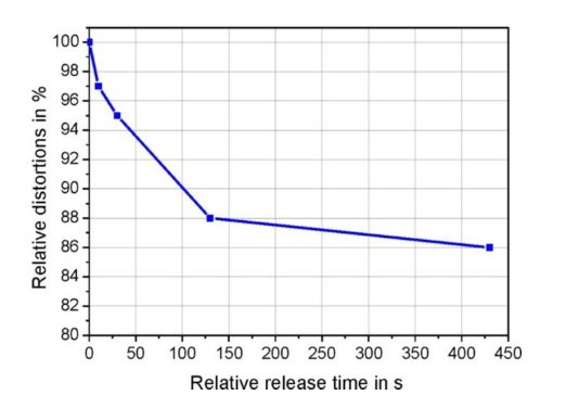
Figure 3: Calculated distortion reduction through longer clamping times after welding.
Where Welding Simulation Is Headed
Welding distortions remain a risk that is hard to quantify during the automotive design process. Especially when using high-strength AHSS, deteriorating dimensional accuracy can cause downstream issues during assembly. By integrating welding simulations in the automotive design and SOP process, these risks can be mitigated and decisions for processing variants can be made before committing capital to fixtures, welding equipment, or tooling.
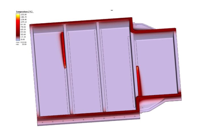
Figure 4: Temperature distribution during welding of a steel battery enclosure.
Several automotive OEMs already use welding simulation in their development processes, but there is still significant untapped potential across the industry. Battery enclosures are among the latest component groups with especially demanding distortion tolerances due to crash and sealing requirements. During the design of steel battery enclosures, welding simulation can help identify robust processing strategies that support compliance with these tight dimensional requirements. In light of current developments aimed at maximizing the available space for battery cells as well as different ways to integrate the battery pack into the vehicle body, advanced welding distortion simulation processes are key to saving costs and minimizing risk at the start of production.
 |
Thanks go to Dr.-Ing Max Biegler, AHSS Application Guidelines Technical Editor and Group Lead, Joining & Coating Technology at Fraunhofer Institute for Production Systems and Design Technology IPK |