Efficient energy and resource use in automotive engineering is a major challenge that can only be overcome with innovative solutions. A cost-effective and resource-saving approach is the use of digital methods in production.
In demanding production chains like body-in-white components from tailor-welded blanks (TWBs), it is crucial to digitally simulate the product before actual production to prevent tool adjustments and unnecessary trials. A new digital twin for the tailor welded blanking process chain links numerical simulations for welding and forming steps. Figure 1 shows a typical application for a tailor welded blank component in the body in white: front longitudinal member.
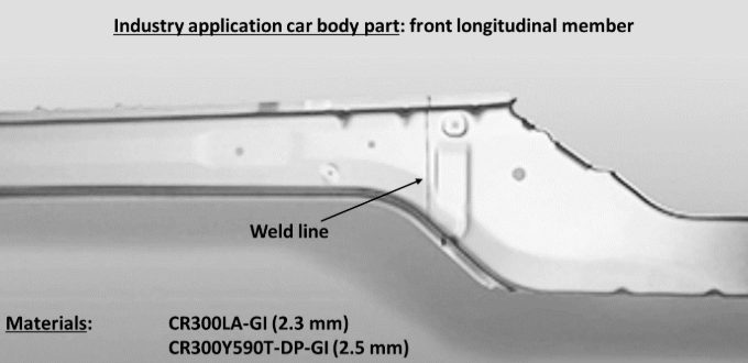
Figure 1: A typical application for TWBs in the automotive industry is the longitudinal member shown here at the front. The TWB shown consists of micro-alloyed CR300 LA (2.3 mm) and high-strength dual phase steel with 600 MPa (2.5 mm). The welded sheet metal blanks were deep-drawn into the final shape of the TWB.
The process chain of laser beam welding and deep drawing faces challenges when pushing to stronger advanced high-strength steels. Areas around the weld seam are susceptible to softening due to heat input during welding, leading to changes in material properties, such as decreased strength in the heat-affected zone (HAZ) and hardening of the weld metal, influencing forming limit behavior.
Adapted welding process control can optimize material properties, ensuring laser beam welding’s applicability for AHSS grades. Consistent digital simulation of manufacturing processes is one of the most promising approaches for enabling low-emission, lightweight construction and maximizing material efficiency. To replace material-intensive experiments, simulations using the finite element analysis (FEA) create a virtual 3D model of a component.
Welding structure simulation validation is performed using thermocouple measurements and metallographic sections. The core of the forming simulation consists of material cards for high-strength steels. Yield curves, stress-strain curves, and forming limit diagrams are incorporated into the simulation. Validation experiments complete the forming simulation setup, comparing the deep-drawing press force-displacement curve with the modeled curve. The deep-drawn component is then digitized using a 3D scanner, allowing comparison of the real component with the simulated one in terms of geometry, defects, and sheet thickness. Figure 2 shows a simulated S-rail as demonstrator component after deep-drawing simulation.
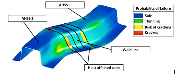
Figure 2: Simulation result of an S-rail formed from TWBs for the probability of failure (max. failure). Both the weld seam and the heat-affected zone are greatly oversized in the illustration for better visibility. The base materials are two high-strength steels of different sheet thicknesses, which were welded together using a butt joint. The heat-affected zone is represented as two areas with different properties.
Today’s forming simulation tools cannot readily account for the small geometric areas of weld metal and heat affected zones, hence the welding simulation results cannot be directly used as input for another software. In addition, it is difficult to measure material behavior of the welding zones to correctly model them in forming simulations. New interfaces were developed for a digital data management platform to bridge this gap. Intermediate steps are required to transfer welding results to forming simulation, including determining the heat-affected zone and deriving weld seam geometry. The analysis chain of the digital twin involves extracting welding simulation results, creating input for forming simulation and adjusting welding simulations based on forming results in an iterative loop. Figure 3 illustrates the digital process chain.
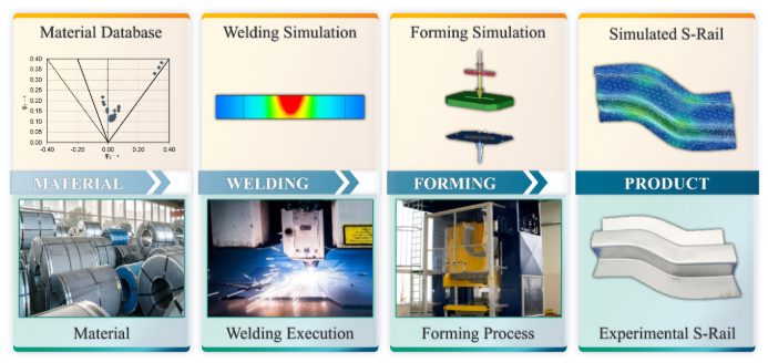
Figure 3: Scheme of the digital (top) and conventional (bottom) process chain of tailor welded blanking: main process steps from material to final product.
Linking welding and forming simulations (Figure 4) enable TWBs made of advanced high-strength steels reach higher strength levels, ultimately saving resources in car body construction and making production more sustainable. The development of TWBs for automotive construction serves as a starting point for expanding lightweight construction potential across the transport sector.
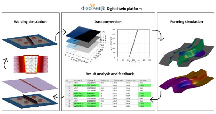
Figure 4: Bidirectional digital twin: How adapting welding simulation closes the loop. The welding simulation displays its results using three-dimensional volume elements. With the help of the digital platform, a simplified two-dimensional representation is generated that contains information about the position of the weld seam and heat-affected zone, which can then be modelled in shell elements. This data is used for the forming simulation and the result is fed back into the digital platform. The parameters of the best simulation results are highlighted and assist in the planning of new welding simulations.

A special thank you to our author, Josefine Lemke, M. Sc. She is a research associate at Fraunhofer IPK in Berlin, Department Joining and Coating Technology. She specialized in additive manufacturing and welding simulation. The focus is on the correlation of component quality and powder properties, particularly in the context of industry and SME environments. She is also working on the qualification of ultra-high-strength steels in car body construction (integration of laser welding and forming simulation in tailor-welded blanking).